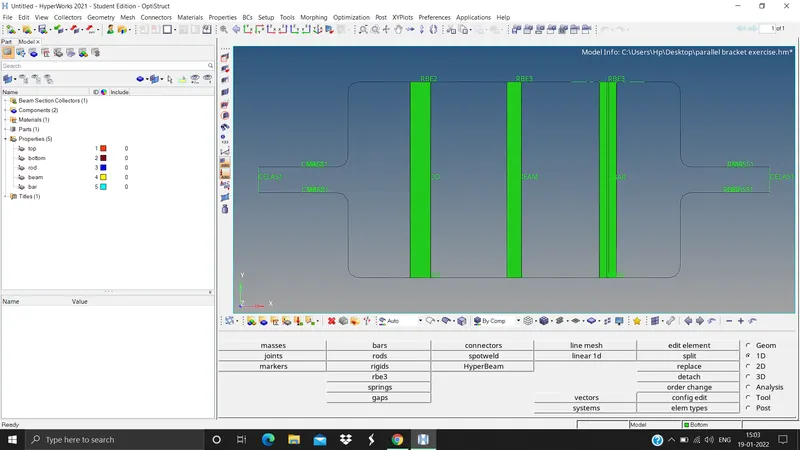
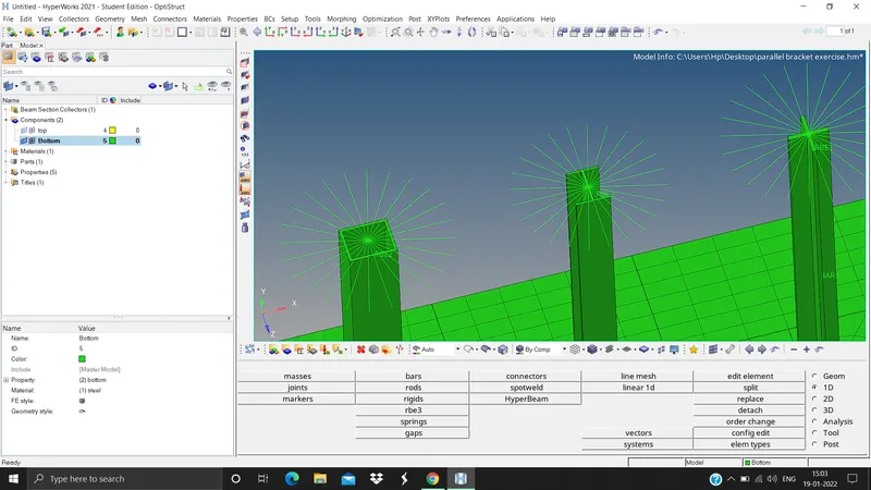
Week 4-1D Element Creation Challenge
1. First import the igs file
File > import > file type iges > import.

2. Clean the unwanted lines, circles, etc.
Click on the "X" icon > select the lines > all > delete entity.
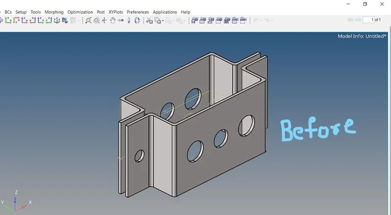
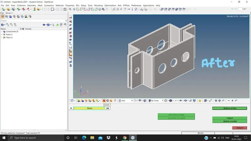
3. Extract the mid surface. There are two brackets so extract the mid surface seperately for both the brackets otherwise both the mid surfaces will be attached to the same bracket only.
For bracket 1.
Geometry panel > midsurface > select the bracket > extract.
For bracket 2.
Rt click on component > create > rename it as bracket 2.
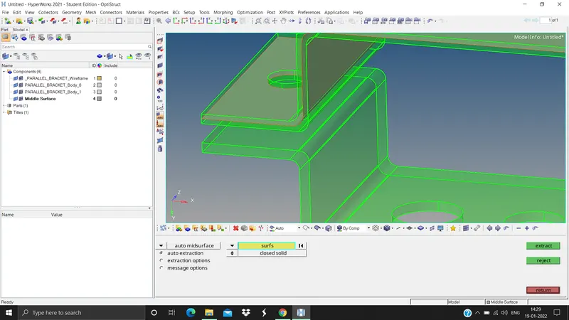
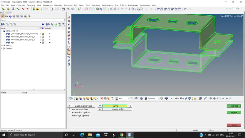
4. Now extract the midsurface of the 2nd bracket
Geometry panel > midsurface > select the bracket > extract.
5. Now since the bracket 2 and the midsurface are seperate we need to assign the created midsurface to bracket2
Tool panel > organise > select surfs > dest component as bracket2 > move.
6. After creating midsurface we no more need the solid component.
Click on the "X" icon > select solids > displayed > delete entity.
Now we need to assign the material Rt click > create > material > rename as steel.
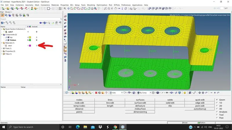
Assign the property to the material Rt click > create > property > rename as bracket1, again Rt click > create > property > rename as bracket 2.
Assign the thickness to the surfaces created. Click on bracket1 > T > 2.0 > card image PSHELL > material steel repeat the same for bracket2 with T= 2.5
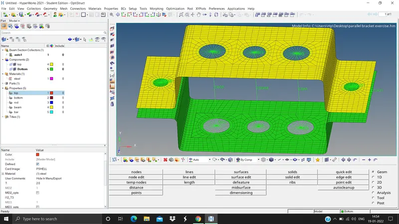
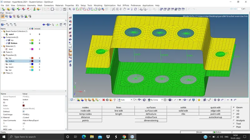
Assign the property to the components Click on bracket1 in component > property Bracket1, repeat the same for bracket2
Now perform the 2D mesh 2D panel > automesh > surfs > displayed > Element size 5 > mesh type mixed > mesh
Now we need to create an RBE2 link for the rod element at position "a" 1D panel > rigids > independent (calculate node > dependent, multiple node > click on the node > by path > select the nodes on the surface around thw washer split > create)
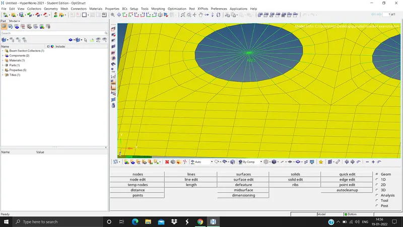
Create RBE3 link for the beam element at position "b" 1D > RBE3 > under dependent click calculate node > under independent click nodes > by path > select the nodes on the surface > create
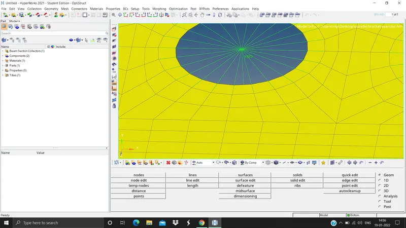
Create the RBE3 link for the bar element at position "c" 1D > RBE3 > under dependent click calculate node > under independent click nodes > by path > select the nodes on the surface > create
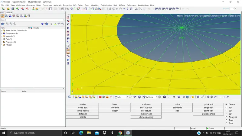
Create RBE2 link at position "d" and "e" and apply the mass of magnitude 10
1D > masses > mass=10 > element type CMASS1 > select the nodes > create.
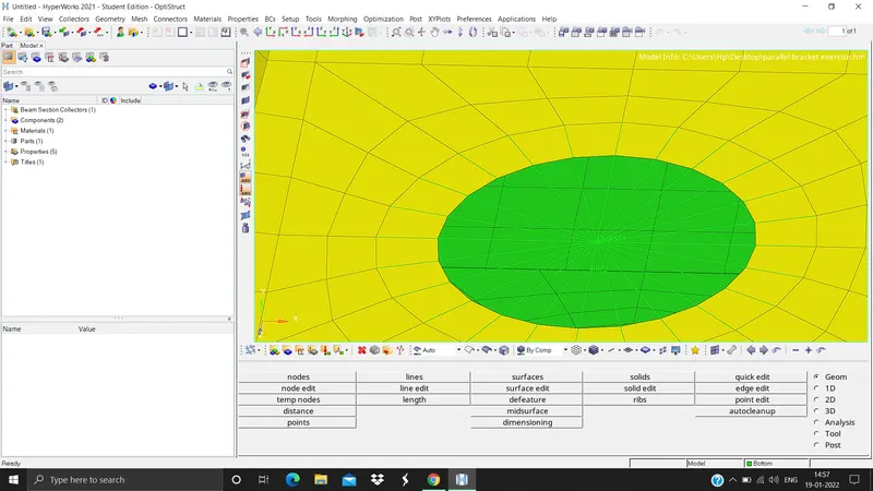
Create the spring elements at position "f"
1D > springs > select 2 nodes node1 and node2 > element type CELAS1 > create.
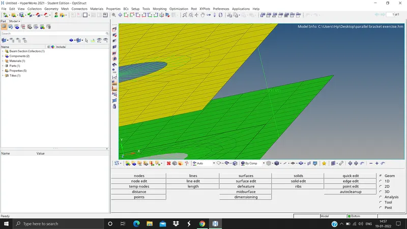
Now we need to create the Cross sections for the given elements
1D > Hyperbeam > standard section > select hyperbeam under standard library > solid rectangle under standard section > create, similarly create the required cross sections using the same method.
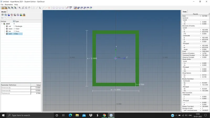
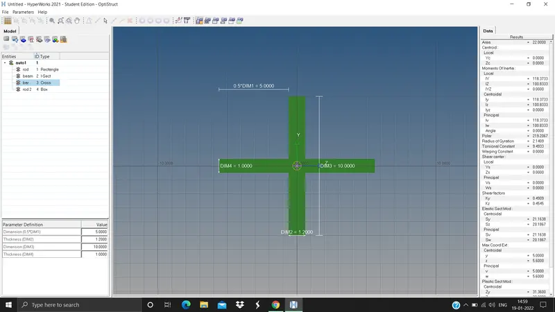
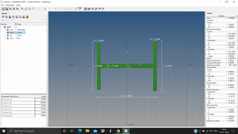
Create a "Rod element" at position a 1D > rods > select the 2 nodes node1 and node2 > element type CROD > click middle mouse button to create the element.
Create a beam element at position b 1D > bars > select the 2 nodes > elemrnt type CBEAM > click the middle mouse button to create the element.
Create a Bar element at position c 1D > bars > select the 2 nodes > element type CBAR > click the mioddle m ouse button to create the element.
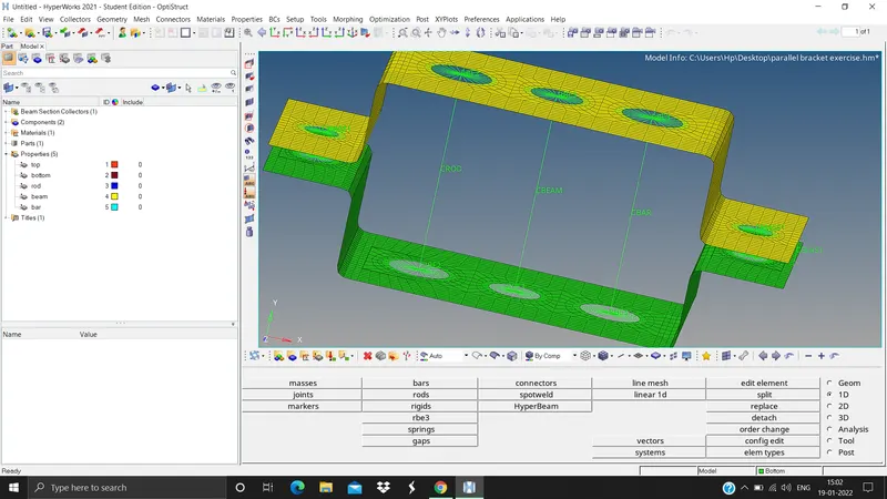
Create 3 seperate properties for three seperate elements rod, beam, bar. Click on Rod > card image PROD > beamsec rod, do the same for beam and bar.
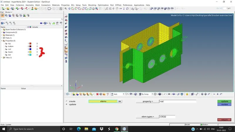
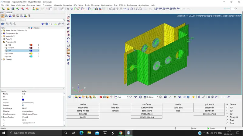
Now we need to update the cross sections to the element properties 1D > Rods > update > under property select Rod > select the rod element > update, do the same for Bar and Beam elements.
Now to see the detailed cross section Under tool bar > 1D detailed element representation.