Week- 5 - Solid meshing
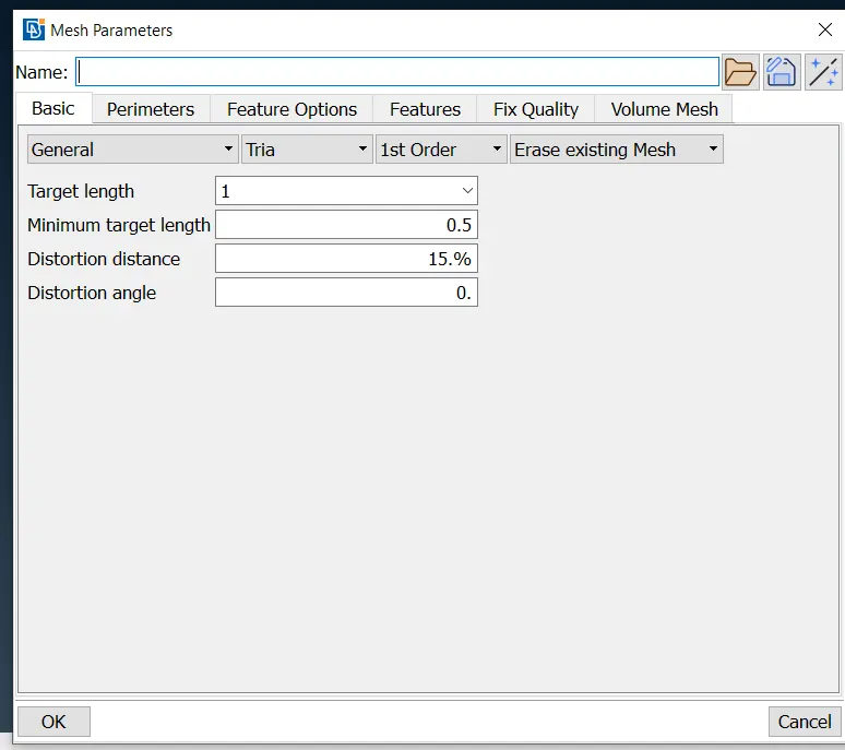
The aim of this challenge is to check for the geometrical errors and mesh the Surfaces with the given 2D element Quality criterias given below and Use tetra elements to mesh the Volumes defined in the model and check for the below quality after Volume meshing.
USE THE BELOW STEPS FOR ALL THE COMPONENTS
Step 1. Import the model (File > open > select the file > open)
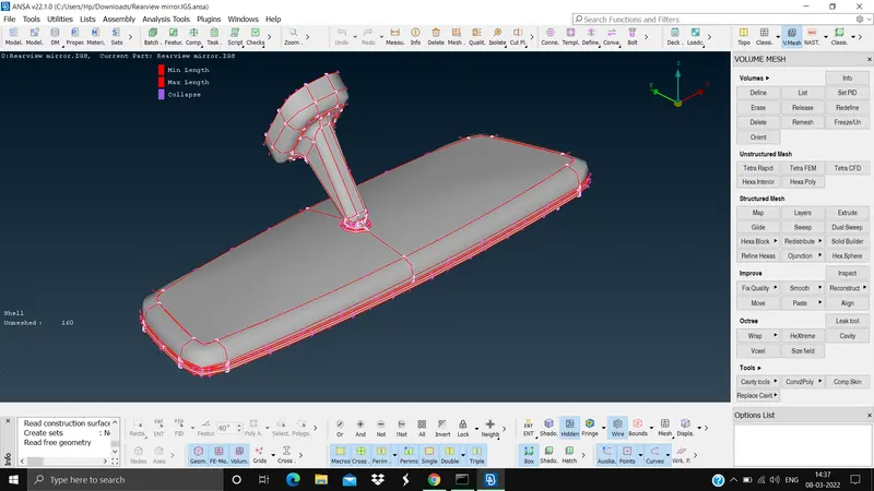
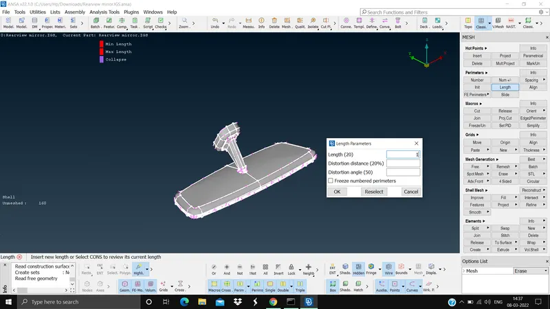
Step 2. Use length option to do cons resolution (Mesh module > perimeters > length > select the model > give length as 1 > ok)
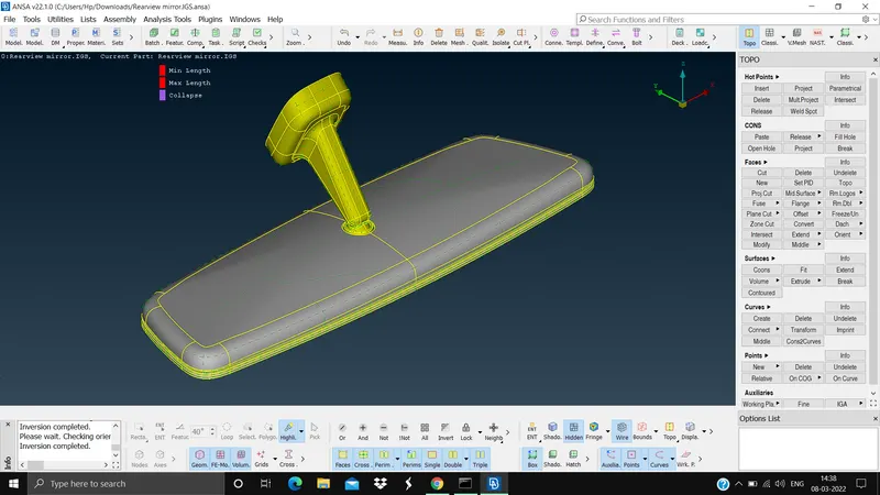
Step 3. Since it is IGES file there will be no connection within the components so we need to provide the connection by using the topo in topo module (Topo module > Faces > topo > select the model > ok), after this we need to do the geometry check to see any other issue (Tools tab > checks > geometry > execute)
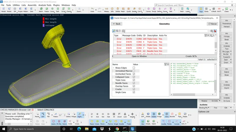
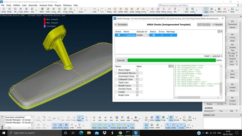
Step 4. We need to do the geometry cleanup where we feel the elements will get failed, measure the distance between 2 points , if the length is ok no need od cleanup, if the distance is less than the element length remove the line (mesh module > macros > join > select the line)
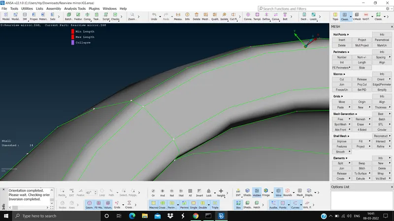
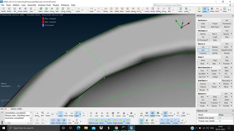
Step 5. First we need to do shell/2d mesh and the convert it to volume mesh, mesh the flat surfaces with tria elements and curved surfaces with ortho tria elements (Mesh module > mesh generation > best > element type tria or ortho tria), now do the volume mesh (V.Mesh module > Volumes > define > select the model > mid mouse click > rt click on the PID > edit > type tetra rapid > ok > again rt click on the PID > remesh)
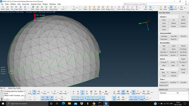
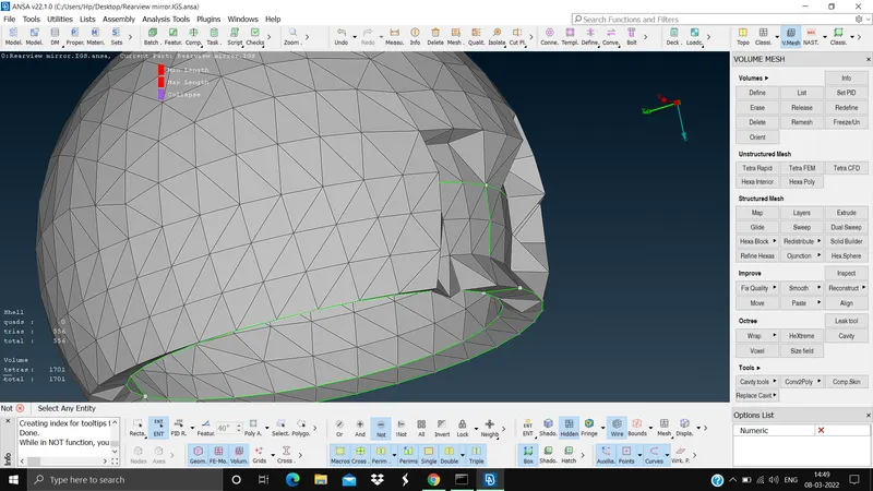
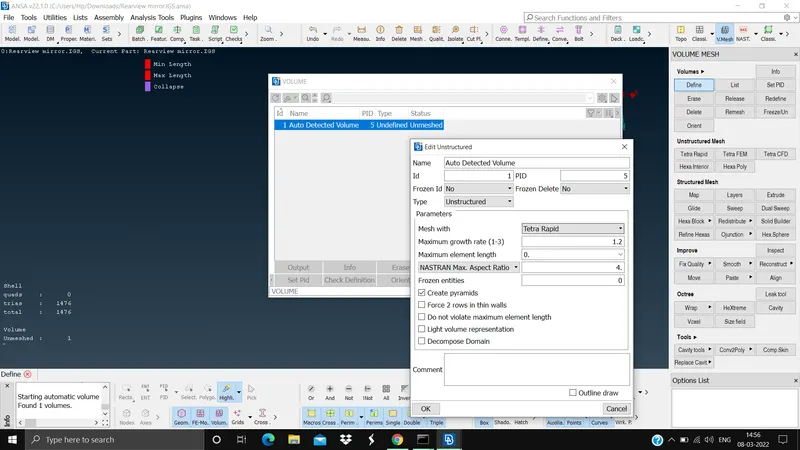
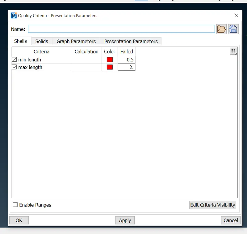
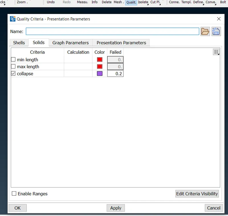
If there are 2d element failures use the reconstruct command to fix them, if the elements are failing for tet collapse then use fix quality command (V.Mesh > Improve > fix quality > visible > ok)
The outcome and conclusion of this challenge is that we have learned how to do volume mesh from 2d shell mesh, how to set diffewrent PIDs for different volumes, how to fix element failures in 2d and 3d elements.