Week 9-Creation of 1D Connectors Challenge
The objective of this challenge is to mesh the given frame assembly according to the given quality criteria and give the 1D connectors to the frame.
In this challenge we are going to learn how to give 1D connections to the assemblies so that we can come to know which parts are connected together using which connector, ex:bars, rods, springs, adhesives, etc.
1. First we need to import the model (File > import > geometry > frame assembly > import)
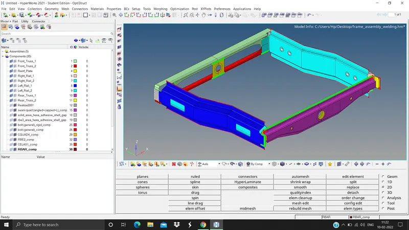
2. Next we need to do geometry cleanup whereever necessary (Geometry panel > autoclean up > surfs > displayed > autocleanup). In this model there is no need to do the geometry cleanup.
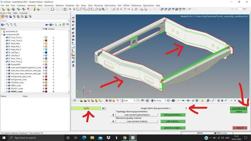
3. We need to delete the solids if present since we are dealing with 2D elements (F2 > solids > displayed > delete entity)
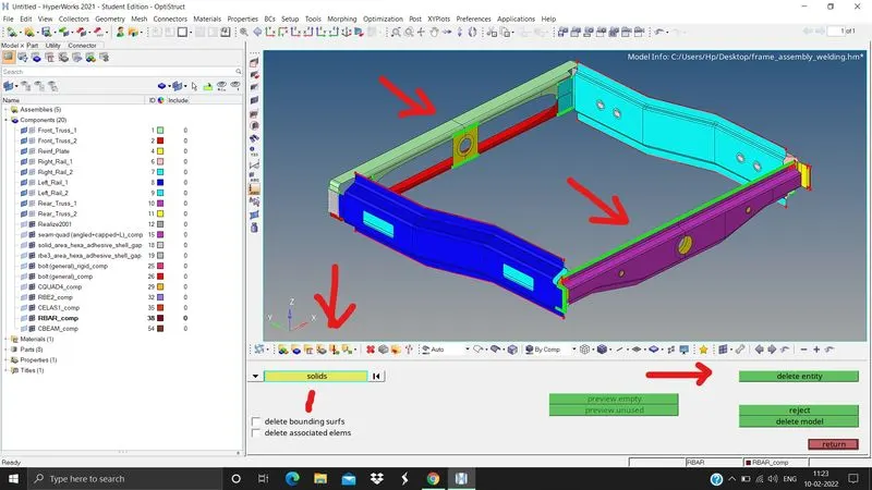
4. In this model there is no need to extract the mid surface as already the frame is in the surface only.
5. Next we need to mesh the given frame assembly with 2D mesh with the element size of 5 units (2D panel > automesh > surfs > displayed > elem size 5 > elem type mixed > mesh)
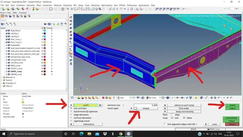
6. After meshing we need to clean the elements by avoiding the tria concentration, rotating quads, etc. This can be done by different ways whichever is applicable.
a. Remeshing the elements (2D panel > automesh > elements > displayed > elem size 5 > elem type mixed or quads > mesh)
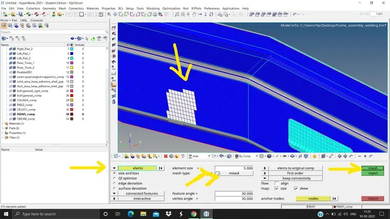
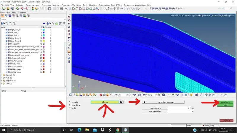
b. Elements edit in 2D panel (2D panel > element edit > combine if there are trias side by side or split if there is a necessary to split the quads)
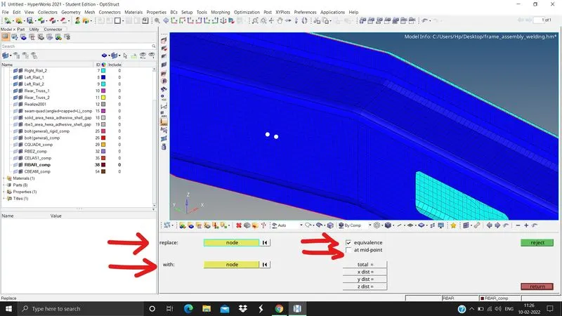
c. replace node (F3 > select the nodes to replace > select the node with which it should be replaced). etc
7. After cleaning the elements we need to check the proper flow of elements
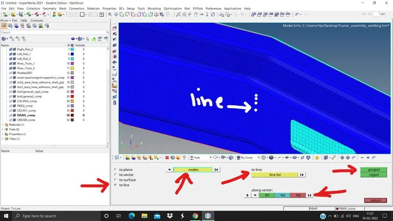
a. Aligning the node with the existing line (Tools panel > project > to ine > select the nodes > select the lines > select the vectors or plane along which the nodes should be aligned)
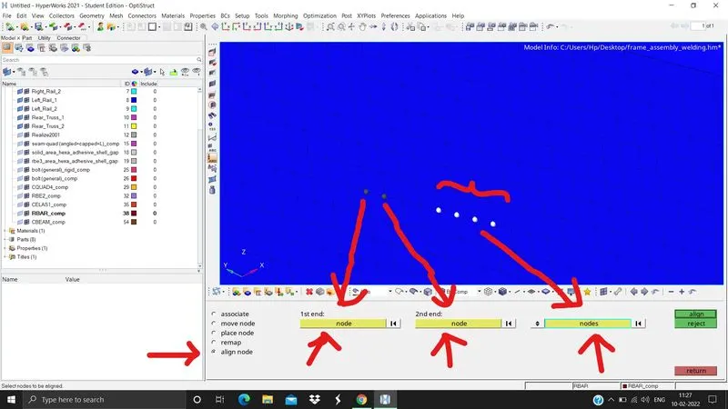
b. Aligning the nodes with other nodes (F7 > align node > select first node and second node > select the node list that are to be aligned)
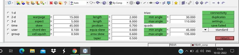
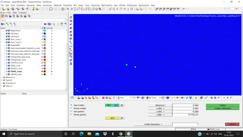
8. Now we should check elements that are that are failing with the quality criteria (F10 > input all the quality criteria data like warpage, skew, aspect ratio, etc), here we can come to know which elements are failing. This can be resolved by adjusting the distance between two nodes by this we can overcome min and max element length as well as quads and tria angles (F4 > two nodes > select the nodes and specify the suitable distance)
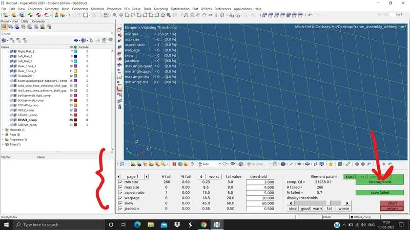
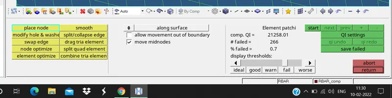
9. After this we need to ckeck for the quality index (2D panel > quality index > input all the necessary data), make sure that the elements are not coloured in red or yellow, if present clean it by using quality index (2D panel > quality index > clean up tools > place node or element optimise or smooth etc)
Now we need to do 1D connectors to the frame assembly
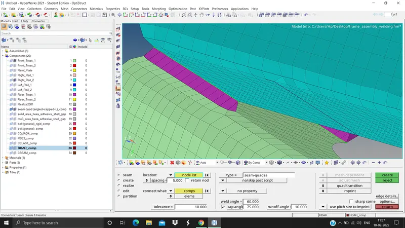
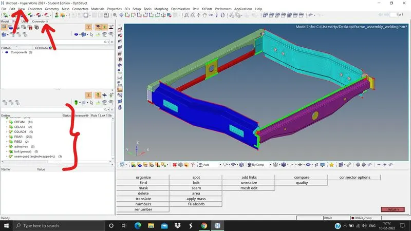
1. Seam-Quad(angled+capped+L) here we need to select Right_Rail_2 & Front_truss_1 (2D panel > connectors > seam > location = node list > by path > select the nodes > spacing = 5units because element size 5 units > tolerance = 10 > type = seam quad [angled+capped+L] > select the components > create). Some times we cannot see the connectors i,e; it is not realized so we need to realize it (view > browsers > hypermesh > connectors)
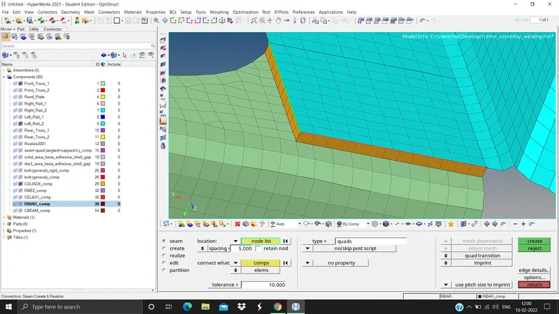
2. Quad elements here we need to select Left_Rail_2 & Front_truss_1 (2D panel > connectors > seam > type quads > location node list > by path > spacing =5 > tolerance = 10 > select the components > create)
3. Spot weld with 2 Layers and 5 mm Diameter here we need to select Front_truss_2, Front_truss_1 & Right_Rail_1 (2D panel > connectors > spot > type weld > location node list > by path > spacing =5 > tolerance = 10 > select the components > num layers total 2 > diameter = 5 > create)
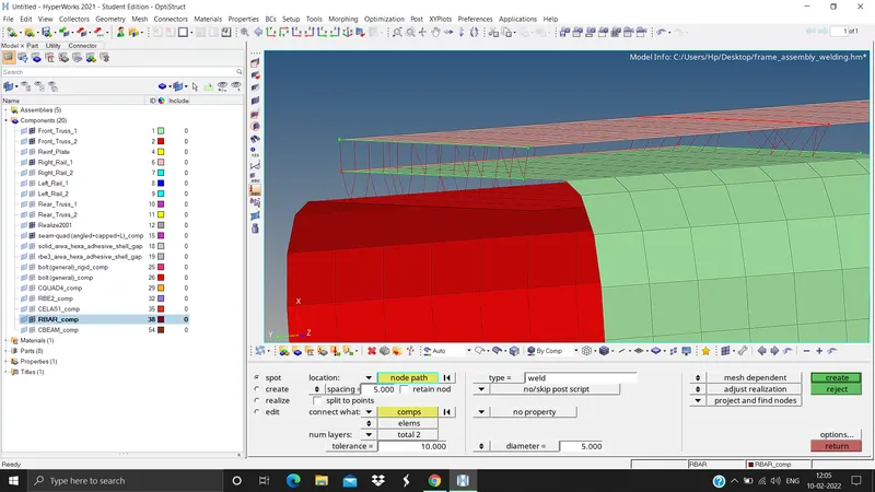
4. Hexa (Adhesive) here we need to select Front_truss_2, Front_truss_1 & Left_Rail_1 (2D panel > connectors > area > type adhesives > location elements > tolerance = 10 > select the components > create)
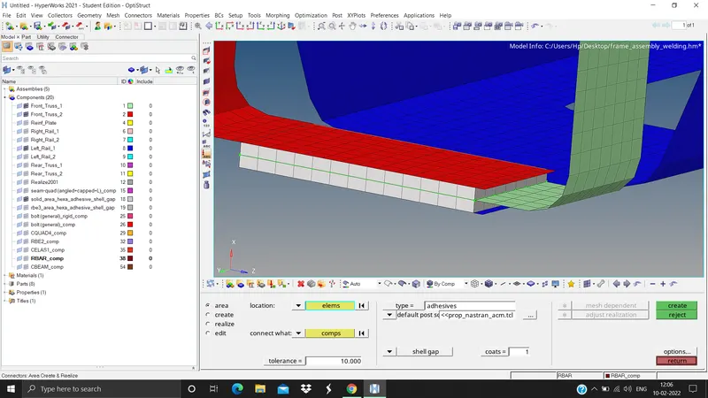
5. Bolt Connector here we need to select Rear_truss_2 & Right_Rail_2 (2D panel > connectors > bolt > type bolt general > location node > select the nodes > tolerance = 10 > create holes if none > select the components > create)
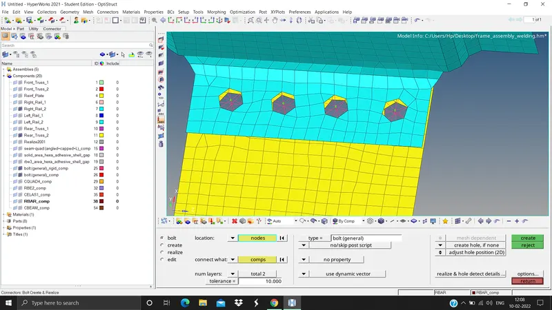
6. Bolt Connector here we need to select Rear_truss_2 & Left_Rail_2 (2D panel > connectors > bolt > type bolt general > location node > select the nodes > tolerance = 10 > create holes if none > select the components > create)
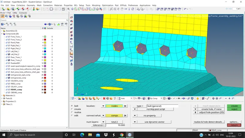
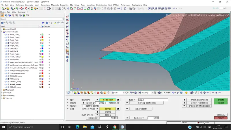
7. Spot-weld with Rigid Elements here we need to select Right_Rail_1 & Right_Rail_2 (2D panel > connectors > spot > type rigid > location node list > by path > select the nodes > tolerance = 10 > spacing = 5 > select the components > create)
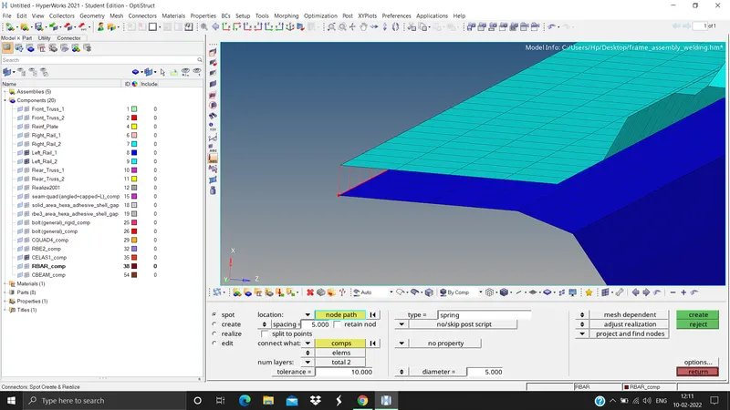
8. Spot-weld with Spring Elements here we need to select Left_Rail_1 & Left_Rail_2 (2D panel > connectors > spot > type spring > location node list > by path > select the nodes > tolerance = 10 > spacing = 5 > select the components > create)
9. Rest all the component left Join them with suitable connectors
RESULTS AND CONCLUSION From this challenge we learnt how to create 1D connectors, how to realise it, and how to attach differenrt parts together with different connectors, and thus learnt 1D connectors concept.