Control logic of washing machine and gear shift logic
AIM: To implement control logic of a “washing machine” using state flow as per given sequence and make a Simulink chat for the “gear shift” logic as per given conditions.
OBJECTIVE:
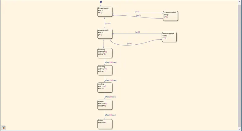
- In Simulink , implementing the control logic of a washing machine using state flow as per given input conditions. If the power supply is available , the system gets activated. If the water supply is not available , stop the process . Soaking time should be 200 seconds followed by washing time of 100 seconds. Then rinsing happens for next 20 seconds and dryer runs for 50 seconds.
- while simulation is running , the gear number is displayed as result.
EXPLANATION:
STUDY 1 : State flow – provides a graphical language that includes state transition diagrams , flow chart , truth tables. With state flow you can model sequential decision logic that can be simulated as a block. Within a Simulink model as an object in MATLAB.
Control logic – The control logic responds to commands from the user , and also acts on its own to perform automated tasks that have been structured into the program .
MATLAB MODEL OF WASHING MACHINE:
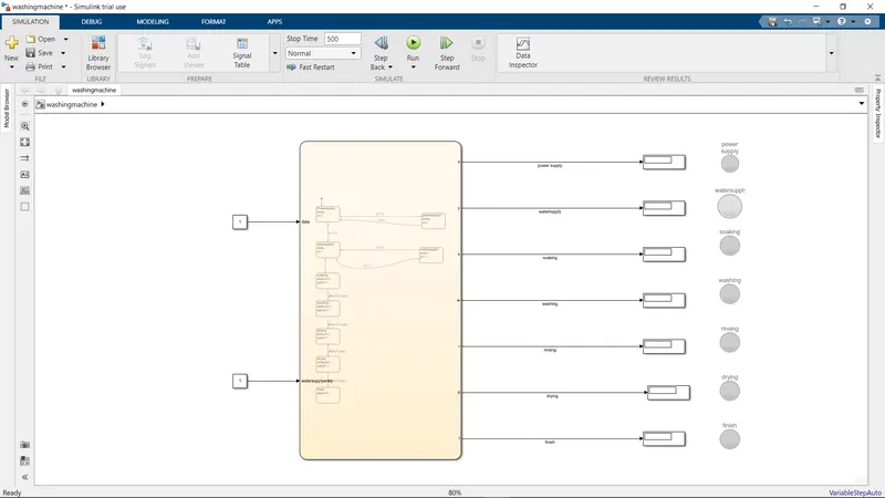
CHART WITH GIVEN INPUT CONDITIONS:
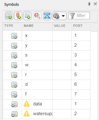
SYMBOLS PANE FOR THE ABOVE MODEL:
After all the processes have completed, the lamps associated with each process gets turned on as a result .
STUDY 2 :
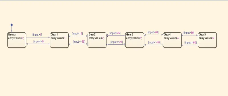
Gear shifting logic has been created and by using "slider gain" block , to vary the speed while running the simulation as an input.
MODEL OF GEAR SHIFTING:
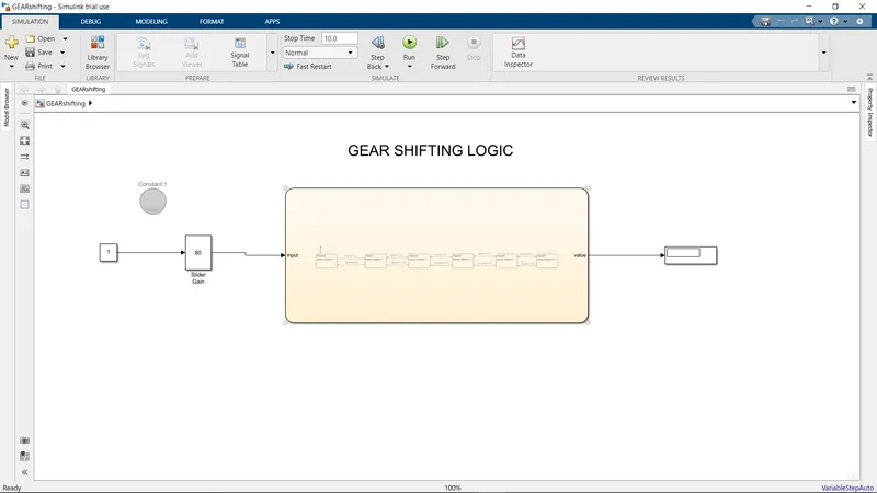
CHART FOR IMPLEMENTING GIVEN SPEED CONDITIONS :
RESULTS:
STUDY 1 :
Control logic of a washing machine using state flow has been implemented. If the power source = 0 , system will not activate or else if the water source is 0 the system will not activate. After all the processes are completed , all the lamps including the finished lamp will glow.
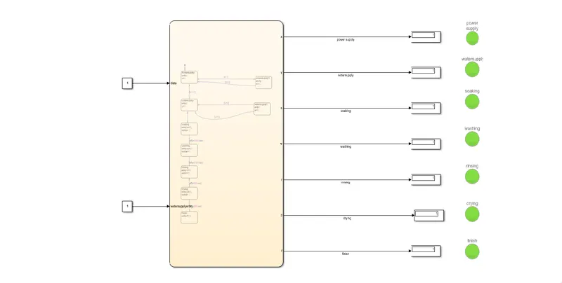
After we give the power source = 1 and water source = 1 , the system will get activated and all the processes along with their respective lamps will glow as per the given conditions.
STUDY 2 :
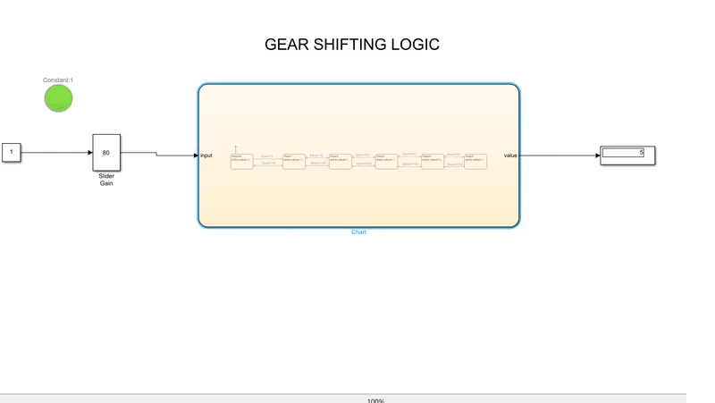
Here , when we enter input conditions , the lamp will be turned on . After that the slider gain is used to implement the given conditions , which are "different speeds." Therefore we entered the speed value as 80 km/hr in the slider gain parameter and as per the given question if the speed is above than 61 km/hr then the veichle should be in 5th gear which is being displayed as result.
CONCLUSION :
In the above experiment , with the help of control logic and state flow we were able to access each individual processes with their given input conditions. when power and water supply are given as input , the soaking process starts , after 200 seconds it moves to washing , after 100 seconds it moves to rinsing , after 20 seconds it moves to drying . Thus the control logic of a washing machine using state flow is processed as per the given sequence and LED lights are turned to green and the system is completed. A simulink model is also created for the gear shift logic and by using slider gain we can input any variable speed value and know the result as gear number in the display.