Week 4.1: Project - Steady state simulation of flow over a throttle body
Aim:
The main objective of this project is to set up the case to perform a simulation of steady-state flow over a Throttle valve when it is fully open and post-processing the result using ParaView.
Introduction:
The report describes the steady-state flow simulation over a Throttle valve using converge CFD software, solving it using CYGWIN and post-processing the result using ParaView. Various steps are discussed in this report while making a case set up for the case study. This report describes the case study with grid sizing, line plots, and contours.
Steady-State Simulation:
This simulation is a steady-state simulation which is the simulation will end when the steady state is reached. The simulation is continuous with respect to the time is a transient state simulation. The measure is in cycles in a steady state but seconds in a transient state.
Geometry:
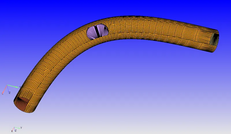
Geometry consists of inlet, outlet, throttle and elbow boundaries.
The geometry is called 0.001 for the appropriate level.
Check the diagnosis for any problem with the geometry and make sure the normals are pointing inwards to the flow.
Flag all the triangles to the appropriate boundaries.
Case Setup:
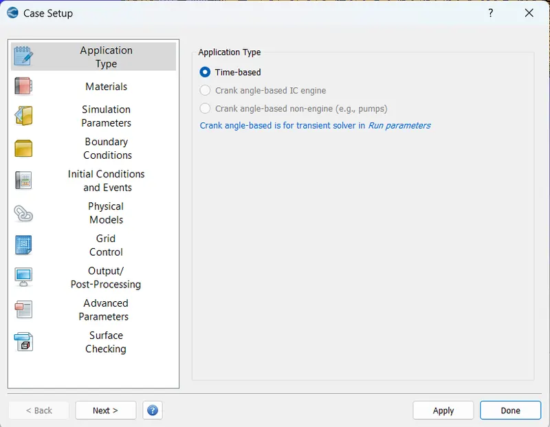
Application type : Time-based Simulation
Materials : Air (O2, N2)
Materials:
Under the material tab "Gas simulation" was selected and "Air" as a predefined mixture.
Gas: Air
Global Transport Parameters: Fixed value
by default, the following value is considered.
Prandtl Number : 0.9
Schmidt Number : 0.78
Species: Oxygen-O2 & Nitrogen-N2
Reaction Mechanism (mech.dat) was selected for this problem.
Simulation Parameters:
Solver: Steady State solver
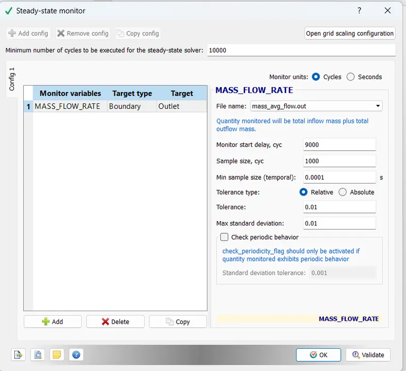
Steady State monitor:
A minimum of 10000 cycles must be executed by the solver and from then 1000 cycles are monitored for mass flow rate at outlet boundary convergence with a tolerance of 0.01.
Simulation time parameters:
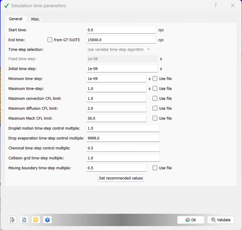
The simulation starts at 0 cycles and will end at 15000 cycles with an initial step of 1e-9 s and minimum and a maximum time step of 1e-9 and 1 s respectively.
The maximum CFL convection limit is 1.0 s.
Solver parameters are in default i.e., PISO solver scheme.
Boundary:
There are four boundaries Inlet, Outlet, Throttle body and Elbow.
Where inlet and outlet are considered has inflow and outflow boundary types respectively. Whereas the throttle body and elbow are considered has a wall-type boundary.
| Boundary Name | Boundary Type | Parameters |
| Inlet | Inflow |
Specified Value: Total Pressure: 150000 Pa Temperature: 300 K Velocity Boundary Condition: NE |
| Outlet | Outflow |
Specified Value: Total Pressure: 100000 Pa Temperature Backflow: 300 K Velocity Boundary Condition: NE |
| Throttle Body | Wall |
Wall Type & Motion: Stationary, Fixed Temperature Boundary Condition: Law of Wall |
|
Elbow |
Wall |
Wall Type & Motion: Stationary, Fixed Temperature Boundary Condition: Law of Wall |
Initial Conditions:
Species: O2 & N2
Pressure: 101325 Pa
Temperature: 300 K
Physical Models:
Turbulence Modelling: RANS, RNG k-`epsi`
Grid Control:
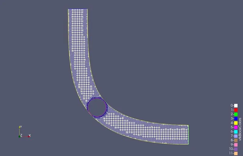
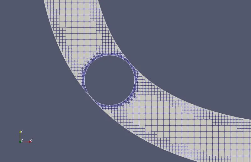
Base grid of 0.02 m in all three directions x,y and z.
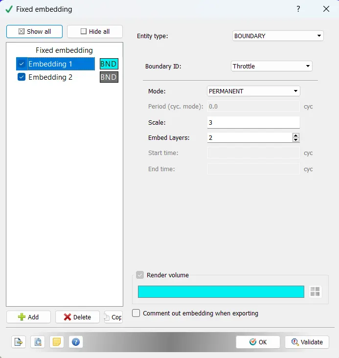
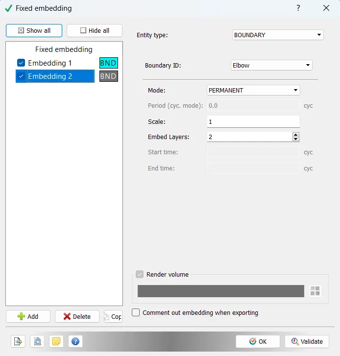
Fixed embedding is selected. Two fixed embeddings are created at the throttle and elbow boundary.
| Entity Type | Boundary ID | Mode | Scale | Embed layers |
| Boundary | Elbow | Permanent | 1 | 2 |
| Boundary | Throttle | Permanent | 3 | 2 |
Output & Post-processing:
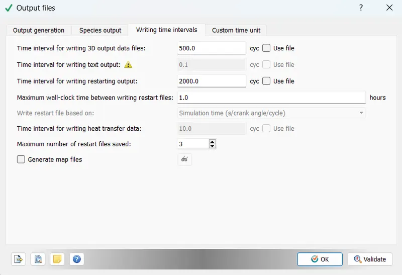
3D output files are written for 500 cycles difference and restart output files at 2000 cycles.
The case set-up is solved in CYGWIN by the command 'mpiexec.exe -n 7 converge.exe restricted </dev/null> logfile &'
Seven processors are used.
The log file is created, and the simulation is run in the background.
Mesh:
Results:
Velocity:
The average velocity at the outlet of the section is steady at 226 m/s
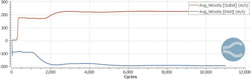
Through the post-processing results in paraview we can observe that the velocity is reached as high as 350 m/s at the throat of the throttle body and remain around 225 at most parts of the body.
The velocity decrease to below 100 m/s after and before the throttle body.
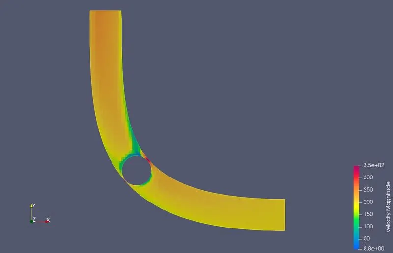
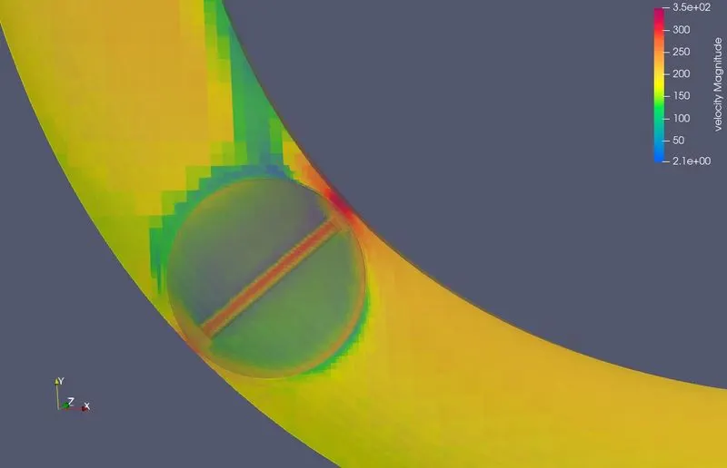
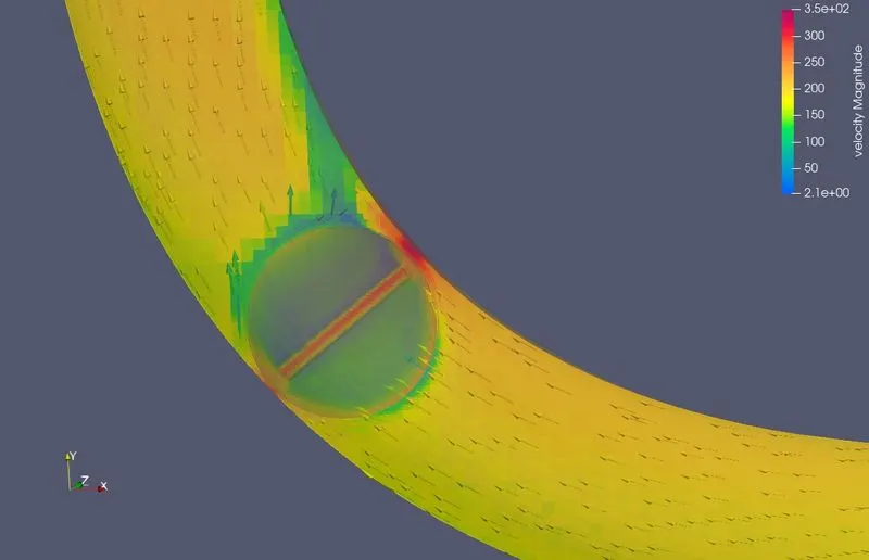
The velocity contour through the elbow-shaped body from start to steady state is shown below.
Pressure:
The total pressure at the outlet of the body is 1.3 bar at steady state condition. The pressure before the throttle reached 1.5 bar and the throat of the throttle is at 0.5 bar where the area decreased.
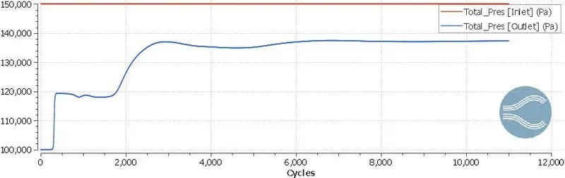
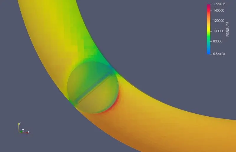
The pressure contour through the elbow-shaped body from start to steady state is shown below.
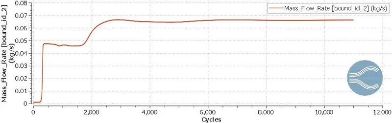
Mass Flow rate at the outlet:
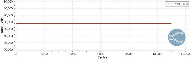
Total Cells:
Conclusion:
Graph for the mass flow rate at the outlet is plotted which 0.066 kg/s after 10,000 cycles became steady. The maximum pressure is at before the throttle body which is at 1.5 bar and the maximum velocity achieved at the throat of the body is 350 m/s and the pressure is minimum at that section. This is because of the decrease in the flow area. The total number of cells is 57,775 including embedding at both the throttle and the boundaries of the elbow. The simulation is ran for 10999 cycles for 5010 seconds.