Week 4.2: Project - Transient simulation of flow over a throttle body
Aim: To set up and simulate the Transient simulation of flow over the throttle body.
Objective:
- Setting up Transient state simulation for flow over a throttle body.
- To generate the mesh that gives more accurate results.
- Post-processing the obtained results using ParaView and show pressure and velocity contour.
Description:
A throttle is a device for controlling fluid flow through the barrier. The throttle controls the power of an engine by managing the quantity of fuel or air that enters the engine. The throttle lever serves as a mechanical coupling. The throttle's butterfly valve is actuated by an arm component that is spring-loaded. This arm is often connected to the accelerator cable and is operated by the driver who hits it. The broader the throttle valve opens, the further the pedal is pushed.
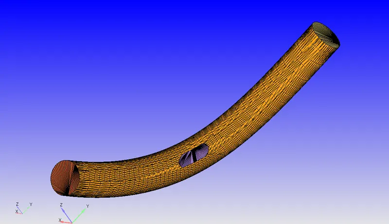
Geometry:
Procedure:
- Initially import the throttle geometry in the converge environment then pre-process by deleting the excess material.
- Geometry consists of inlet, outlet, throttle and elbow boundaries.
- The geometry is called 0.001 for the appropriate level.
- Check the diagnosis for any problem with the geometry and make sure the normals are pointing inwards to the flow.
- Flag all the triangles to the appropriate boundaries.
Case Setup:
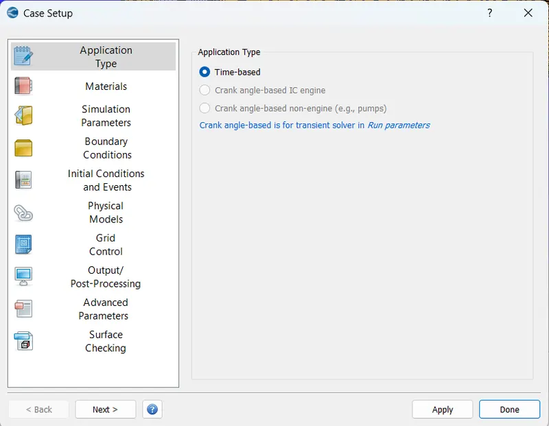
Application type : Time-based Simulation
Materials : Air (O2, N2)
Materials:
Under the material tab "Gas simulation" was selected and "Air" as a predefined mixture.
Gas: Air
Global Transport Parameters: Fixed value
by default, the following value is considered.
Prandtl Number : 0.9
Schmidt Number : 0.78
Species: Oxygen-O2 & Nitrogen-N2
Reaction Mechanism (mech.dat) was selected for this problem.
Simulation Parameters:
Solver: Transient
Simulation Mode: Full Hydrodynamic
Simulation time parameters:
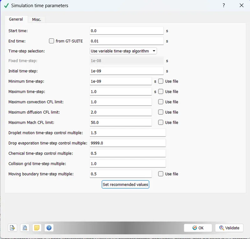
The simulation is run from 0s to 0.01 s with an initial time step of 1e-9s and minimum and maximum time steps of 1e-09 and 1s respectively.
The end time is calculated by the formula `velocity = (distance)/(time)`. and my velocity through steady-state simulations is 226m/s and the length is 0.2 m.
So, the time is 0.00088496 s. which means a particle will take this time to reach the end of the pipe from the start. Run cycles are 11 then the time approximated to 0.01s
Boundary:
There are four boundaries Inlet, Outlet, Throttle body and Elbow.
Where inlet and outlet are considered has inflow and outflow boundary types respectively. Whereas the throttle body and elbow are considered has a wall-type boundary.
| Boundary Name | Boundary Type | Parameters |
| Inlet | Inflow |
Specified Value: Total Pressure: 150000 Pa Temperature: 300 K Velocity Boundary Condition: NE |
| Outlet | Outflow |
Specified Value: Total Pressure: 100000 Pa Temperature Backflow: 300 K Velocity Boundary Condition: NE |
| Throttle Body | Wall |
Wall Type & Motion: Rotating, Moving Temperature Boundary Condition: Law of Wall |
|
Elbow |
Wall |
Wall Type & Motion: Stationary, Fixed Temperature Boundary Condition: Law of Wall |
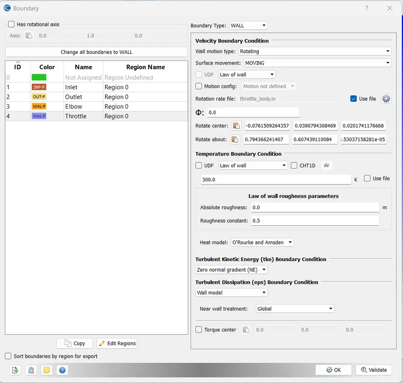
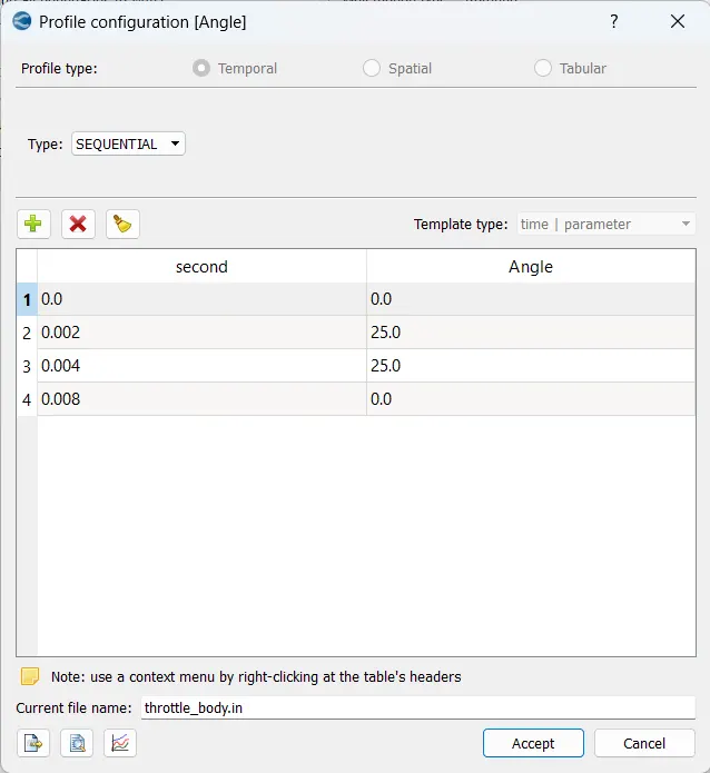
The rotation centre and axis are measured through Geometry > Measure > Direction > Arc Normal > select the three points of the arc > Apply.
The rotation centre and axis will be displayed in the message log which is:

The throttle is rotated to 25 deg at 0.002s and stays at that position up to 0.004s and returns to the original position at 0.008s.
Initial Conditions:
Species: O2 & N2
Pressure: 101325 Pa
Temperature: 300 K
Physical Models:
Turbulence Modelling: RANS, RNG k-εε
Grid Control:
Base grid of 0.02 m in all three directions x,y and z.
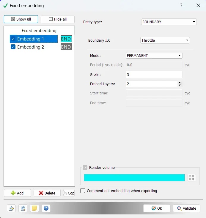
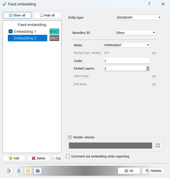
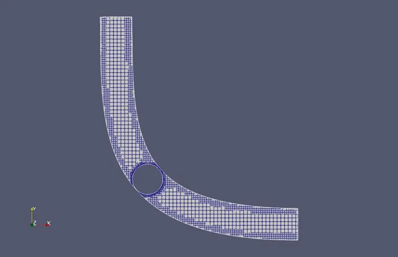
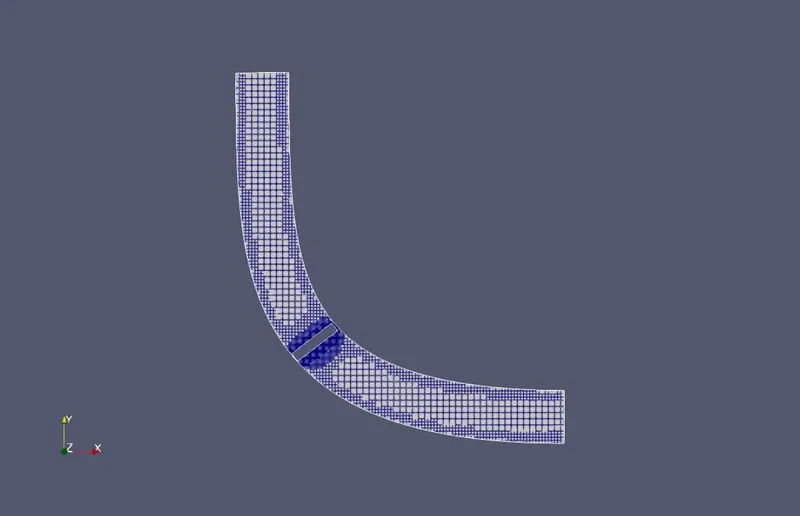
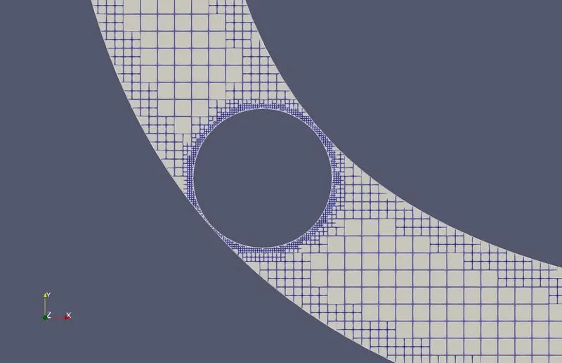
Fixed embedding is selected. Two fixed embeddings are created at the throttle and elbow boundary.
| Entity Type | Boundary ID | Mode | Scale | Embed layers |
| Boundary | Elbow | Permanent | 1 | 2 |
| Boundary | Throttle | Permanent | 3 | 2 |
Output & Post-processing:
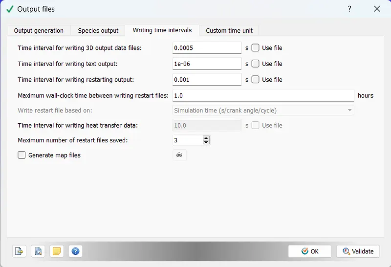
The case set-up is solved in CYGWIN by the command 'mpiexec.exe -n 7 converge.exe restricted </dev/null> logfile &'
Seven processors are used.
The log file is created, and the simulation is run in the background.
Results:
Mesh:
The mesh was structured in way that finer near wall and the near throttle body and coarser at the locations. Fixed embedding is used for this.
Velocity:
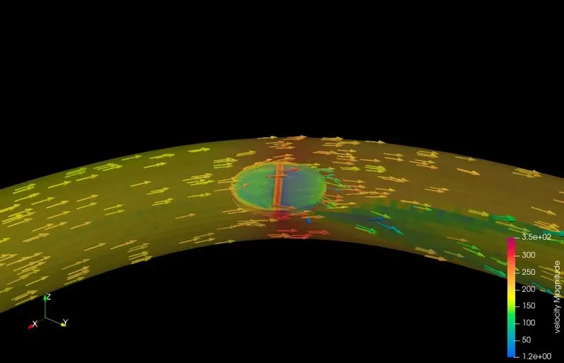
The average velocity at outlet changes throughout time and settled at 225 m/s at the end of the simulation time.
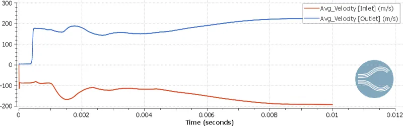
We can see that the flow is from left to right. Velocity reaches a maximum at the ends of the throttle because of a decrease in area. The below picture is at end of the simulation.
The below picture is captured at the 10th time step of the simulation.
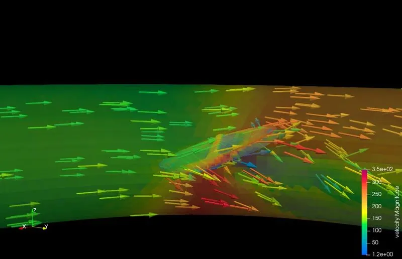
The below picture is captured at the 2nd time step of the simulation.
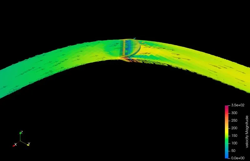
The below picture is captured at the 10th time step of the simulation.
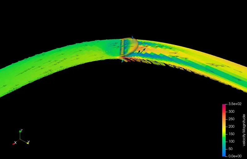
The below picture is captured at the 20th time step of the simulation.
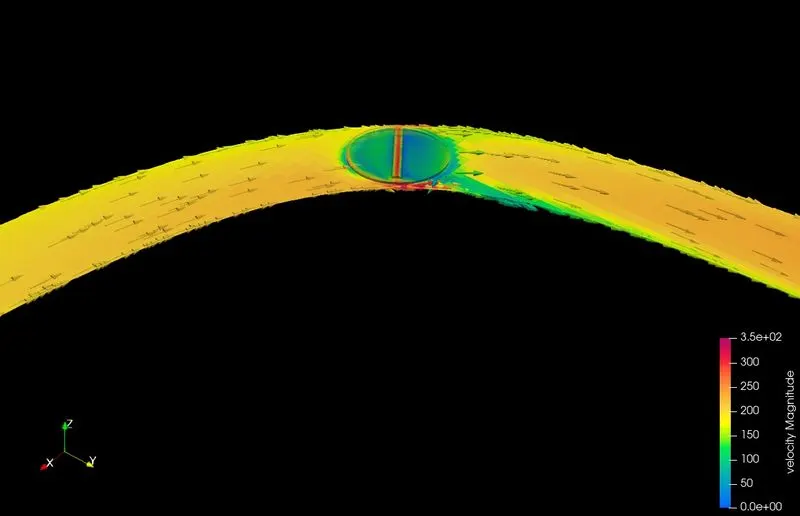
The velocity contour and stream line flow through the elbow-shaped body from start to end is shown below.
Pressure:
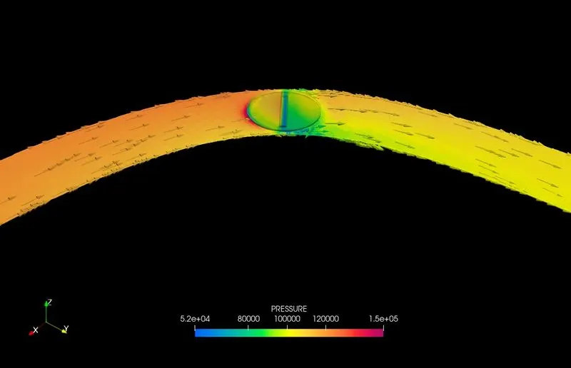
The total pressure at the inlet is study at 150,000pa and the outlet changes from 100,000pa to 135,000pa.
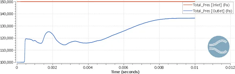
The upstream region area of the throttle where the flow is impinging has higher pressure and on the back portion of the throttle, the pressure is minimum due to flow separation and vacuum creation. The velocity is maximum at the side of the throttle due to the creation of venturi (low area region) and there is negative pressure behind the throttle due to the sudden breaking of flow.
Behind the throttle, the velocity is minimum because there is a flow separation, leaving a vacuum or low-pressure space in which air is not able to fill properly. This leads to the formation of vortices due to changing of velocity gradient from a positive into a negative value at this point. Hence this point is called a Point of separation. In this point of Separation, the velocity profile du/dy is 0 at the wall. If the adverse pressure gradient acts over a sufficiently extended distance, the deceleration in the flow will be sufficient to change the direction of the flow in the Boundary layer. Hence the Boundary layer develops the Point of Inflection, known as the point of Boundary layer Separation beyond which a circular flow pattern is established.
The below picture is captured at the 2nd time step of the simulation.
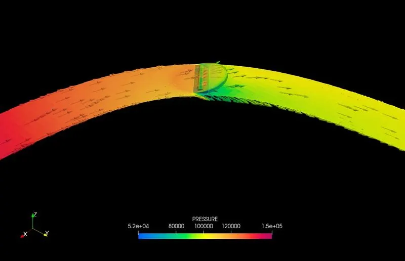
The below picture is captured at the 10th time step of the simulation.
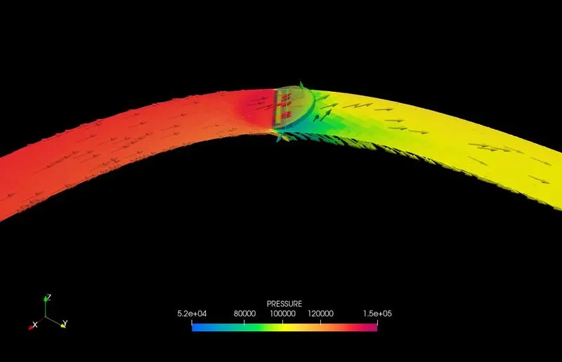
The below picture is captured at the 20th time step of the simulation.
Mass Flow rate:
Total No.of Cells:
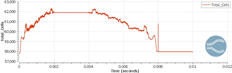
The total no.of cells is changing because of the rotation as we can see that when no rotation from 0.002s to 0.004s the cells are constant. Changes again from 0.004s to 0.008s then it maintained constant throughout.
Conclusion:
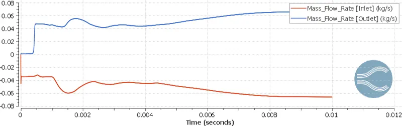
- We can observe from the above plots of pressure, velocity, and mass flow rate that the mass flow rate and velocity rise fast for the period of 0-0.002s for the valve angle of 25 degrees, whilst the pressure decreases swiftly. This is because of the abrupt drop in area, which serves as a venturi or nozzle. The valve is idle as the time grows from 0.002-0.004s. And after 0.004-0.008s, the valve returns to its original position, increasing the area and progressively decreasing pressure while increasing velocity and mass flow rate. The mass flow rate, pressure, and velocity are all constant after 0.008s.
- The velocity is low behind the throttle because there is a flow separation, leaving a vacuum or low-pressure region that air cannot fully fill. This causes vortices to develop as the velocity gradient changes from positive to negative at this moment. As a result, this location is known as a point of separation. The velocity profile du/dy is 0 at the wall at this point of separation. If the unfavourable pressure gradient acts over a sufficiently long distance, the flow slowdown is sufficient to shift the flow direction in the Boundary layer. As a result, the Boundary layer generates the Point of Inflection, also known as the Boundary layer Separation, beyond which a circular flow pattern is produced.