Week 8 - Simulation of a backward facing step in OpenFOAM
Aim:
- Simulate an incompressible laminar viscous flow through the backwards facing step geometry
- Perform transient simulation
- Explain the simulation setup of the problem in OpenFoam
- Perform two case studies one without using grading factor and the other with the grading factor of 0.2
Objectives:
- Copy a similar OpenFoam tutorial
- Edit the tutorial for the required geometry and mesh specifications
- Run the simulation for both the cases without GF and GF = 0.2
- Plot the velocity profile at point 0.085m from inlet for both cases
- Compare the results
Problem Statement:
Simulate an incompressible-laminar-viscous flow through the backward facing step geometry for two cases.
Case 1: Without grading factor GF = 1
Case 2: Grading factor of 0.2
Boundary condition Specifications:
Setup Case:
Open terminal in the Linux operating system
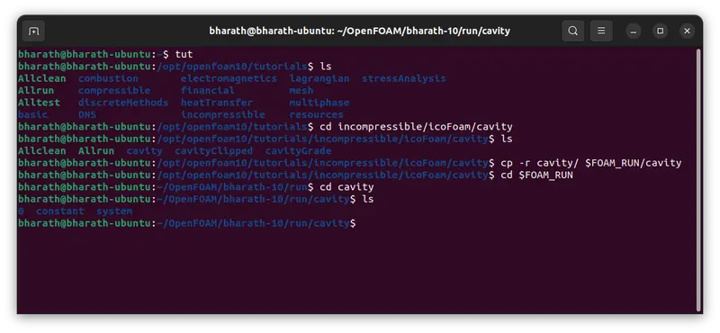
Now, solving the problem using tutorials open tutorials by typing 'tut' and enter command 'ls' for the list in tutorials directory and enter 'cd incompressible/icoFoam/cavity' command to enter into the desired solver folder.
Copy the cavity folder and paste it in the foam run folder. To perform enter 'cp -r cavity $FOAM_RUN/cavity' command
Open the case folder in the foam run by entering 'cd $FOAM_RUN/cavity'
Enter 'ls' command to make sure all the folders are copied which include System, Constant, 0.
Files:
BlockMeshDict:
blockMeshDict file in the system has the geometry and mesh details where the first seven lines of the file will be header as shown below
/*--------------------------------*- C++ -*----------------------------------*\
  =========                 |
  \\      /  F ield         | OpenFOAM: The Open Source CFD Toolbox
   \\    /   O peration     | Website:  https://openfoam.org
    \\  /    A nd           | Version:  10
     \\/     M anipulation  |
\*---------------------------------------------------------------------------*/
Next lines indicates the type of file, file identifier, class, object, format
FoamFile
{
    format      ascii;
    class       dictionary;
    object      blockMeshDict;
}
// * * * * * * * * * * * * * * * * * * * * * * * * * * * * * * * * * * * * * //
Further to set the units in meters, by converting all type of length in to meter. Then the vertices of the backward step are coded from 0 to 25 with (x1 x2 x3) are the coordinates of the vertices.
vertices
(
    (0		0	0)		//0
    (0		0.05	0)		//1
    (0		0.1	0)		//2
    (0.8	0.1	0)		//3
    (2		0.1	0)		//4
    (2		0.05	0)		//5
    (2		0	0)		//6
    (2		-0.05	0)		//7
    (2		-0.1	0)		//8
    (0.8	-0.1	0)		//9
    (0.8	-0.05	0)		//10
    (0.8	0	0)		//11
    (0.8	0.05	0)		//12
    (0		0	0.01)		//13
    (0		0.05	0.01)		//14
    (0		0.1	0.01)		//15
    (0.8	0.1	0.01)		//16
    (2		0.1	0.01)		//17
    (2		0.05	0.01)		//18
    (2		0	0.01)		//19
    (2		-0.05	0.01)		//20
    (2		-0.1	0.01)		//21
    (0.8	-0.1	0.01)		//22
    (0.8	-0.05	0.01)		//23
    (0.8	0	0.01)		//24
    (0.8	0.05	0.01)		//25
);
Now to generate the mesh first create the blocks with the above vertices then the number of cells in X, Y and Z direction are specified further grading is specified. 'hex' denotes the type of block which means hexahedral paranthesis after hex we specify the vertices of the block then the mesh size then grading.
Grading factor or expansion ratios:-
The expansion ratios enables the mesh to be graded, or refined, in specified directions. The ratio is that of the width of the end cell δe along one edge of a block to the width of the start cell δs along the edge as shown in below figure.
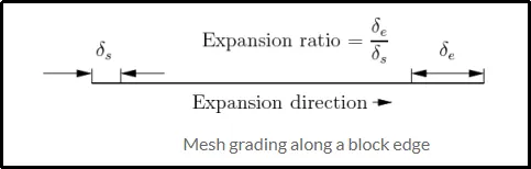
Exapnsion Ratio = (size of end cell)/(size of the starting cell)
blocks
(
    hex (0 11 12 1 13 24 25 14) (200 20 1) simpleGrading (1 1 1)
    hex (1 12 3 2 14 25 16 15)  (200 20 1) simpleGrading (1 1 1)
    hex (12 5 4 3 25 18 17 16)  (200 20 1) simpleGrading (1 1 1)
    hex (11 6 5 12 24 19 18 25) (200 20 1) simpleGrading (1 1 1)
    hex (10 7 6 11 23 20 19 24) (200 20 1) simpleGrading (1 1 1)
    hex (9 8 7 10 22 21 20 23)  (200 20 1) simpleGrading (1 1 1)

);
Here we defined 6 blocks with 200 number of cell in x direction and 20 in y direction and 1 in z direction with simplegrading of 1 in each direction.
Boundary conditions are specified by using the block facesand should specify the type of boundary like wall and empty. Where the empty type means considering it to be 2 dimensional model at that face.
boundary
(
    inlet
    {
        type wall;
        faces
        (
            (0 13 14 1)
            (1 14 15 2)
        );
    }
    outlet
    {
    	type wall;
    	faces
    	(
    	    (5 4 17 18)
    	    (6 5 18 19)
    	    (7 6 19 20)
    	    (8 7 20 21)
    	);
    }
    frontAndBack
    {
        type empty;
        faces
        (
            (15 14 25 16)
            (14 13 24 25)
            (16 25 18 17)
            (25 24 19 18)
            (24 23 20 19)
            (23 22 21 20)
            (1 2 3 12)
            (0 1 12 11)
            (3 4 5 12)
            (12 5 6 11)
            (11 6 7 10)
            (10 7 8 9)
        );
    }
    fixedwalls
    {
        type wall;
        faces
        (
            (3 2 15 16)
            (4 3 16 17)
            (0 11 24 13)
            (9 8 21 22)
            (11 10 23 24)
            (10 9 22 23)
        );
    }
);
ControlDict:
After editing the blockMesh file controldict file has to be edited for the control of simulation like step time, start time and endtime etc.
The simulation will run for 2 seconds with the step time of 0.00001.
/*--------------------------------*- C++ -*----------------------------------*\
  =========                 |
  \\      /  F ield         | OpenFOAM: The Open Source CFD Toolbox
   \\    /   O peration     | Website:  https://openfoam.org
    \\  /    A nd           | Version:  10
     \\/     M anipulation  |
\*---------------------------------------------------------------------------*/
FoamFile
{
    format      ascii;
    class       dictionary;
    location    "system";
    object      controlDict;
}
// * * * * * * * * * * * * * * * * * * * * * * * * * * * * * * * * * * * * * //

application     icoFoam;

startFrom       startTime;

startTime       0;

stopAt          endTime;

endTime         2;

deltaT          0.00001;

writeControl    timeStep;

writeInterval   20;

purgeWrite      0;

writeFormat     ascii;

writePrecision  6;

writeCompression off;

timeFormat      general;

timePrecision   6;

runTimeModifiable true;


// ************************************************************************* //
Intial Setting for Velocity:
As blockMesh this file start with header and the file details then the dimensions of the velocity is specified then the internal field is specified then boundary field of each faces then type and the value here the inlet faces have fixed value of 1 m/s in x direction and 0 in y,z direction.and outlet faces are of type zerogradient, fixedwalls have no slip uniform value of 0 in all directions and front and back faces are of type empty.
/*--------------------------------*- C++ -*----------------------------------*\
  =========                 |
  \\      /  F ield         | OpenFOAM: The Open Source CFD Toolbox
   \\    /   O peration     | Website:  https://openfoam.org
    \\  /    A nd           | Version:  10
     \\/     M anipulation  |
\*---------------------------------------------------------------------------*/
FoamFile
{
    format      ascii;
    class       volVectorField;
    object      U;
}
// * * * * * * * * * * * * * * * * * * * * * * * * * * * * * * * * * * * * * //

dimensions      [0 1 -1 0 0 0 0];

internalField   uniform (0 0 0);

boundaryField
{
    inlet
    {
        type            fixedValue;
        value           uniform (1 0 0);
    }

    outlet
    {
    	type		zeroGradient;
    }

    fixedwalls
    {
        type            noSlip;
        value		uniform (0 0 0);
    }

    frontAndBack
    {
        type            empty;
    }
}

// ************************************************************************* //
Intial Setting for Pressure:
As stated above in the velocity file the boundary conditions of pressure are included in here
inlet faces are of type zerogradient, oulet as fixedvalue and the value of 0 and fixedwalls of zerogradient and frontand back are considered as empty.
/*--------------------------------*- C++ -*----------------------------------*\
  =========                 |
  \\      /  F ield         | OpenFOAM: The Open Source CFD Toolbox
   \\    /   O peration     | Website:  https://openfoam.org
    \\  /    A nd           | Version:  10
     \\/     M anipulation  |
\*---------------------------------------------------------------------------*/
FoamFile
{
    format      ascii;
    class       volScalarField;
    object      p;
}
// * * * * * * * * * * * * * * * * * * * * * * * * * * * * * * * * * * * * * //

dimensions      [0 2 -2 0 0 0 0];

internalField   uniform 0;

boundaryField
{
    inlet
    {
        type            zeroGradient;
    }

    outlet
    {
    	type		fixedValue;
    	value		uniform 0;
    }

    fixedwalls
    {
        type            zeroGradient;
    }

    frontAndBack
    {
        type            empty;
    }
}

// ************************************************************************* //
Now all the above file blockMeshDict, controlDict, velocity and pressure boundary files are edited to the required geometry, mesh and the boundary conditions.
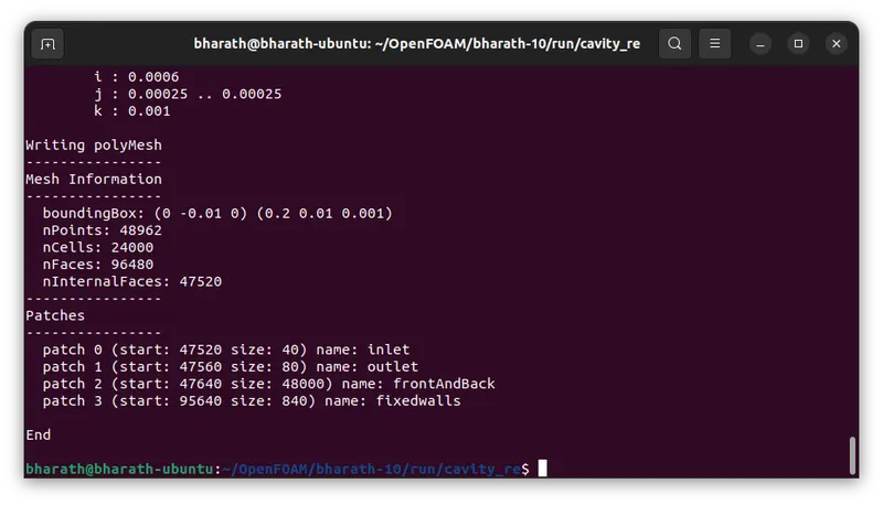
Enter the 'blockMesh' command to create the mesh
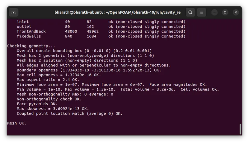
Enter 'checkMesh' command to check the mesh
At this stage we can view the geometry with mesh in the paraview by executing the command 'paraFoam'
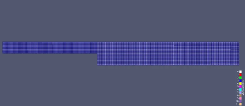
Then execute the command 'icoFoam' or else 'icoFoam > log &' to run the simulation background and can view the log by entering 'cat log' command.
Post-processing:
Open paraview to view the results
Velocity distribution:
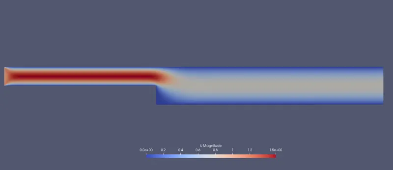
Pressure distribution:
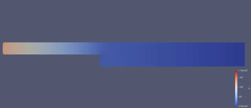
Velocity distribution at 0.085 m from inlet:
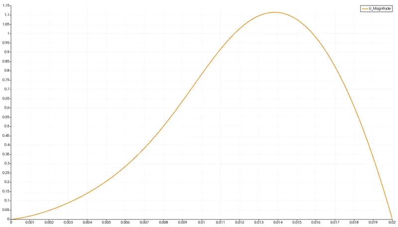
Grading Factor 0.2:
the blockMeshDict file:
/*--------------------------------*- C++ -*----------------------------------*\
  =========                 |
  \\      /  F ield         | OpenFOAM: The Open Source CFD Toolbox
   \\    /   O peration     | Website:  https://openfoam.org
    \\  /    A nd           | Version:  10
     \\/     M anipulation  |
\*---------------------------------------------------------------------------*/
FoamFile
{
    format      ascii;
    class       dictionary;
    object      blockMeshDict;
}
// * * * * * * * * * * * * * * * * * * * * * * * * * * * * * * * * * * * * * //

convertToMeters 0.1;

vertices
(
    (0		0	0)		//0
    (0		0.05	0)		//1
    (0		0.1	0)		//2
    (0.8	0.1	0)		//3
    (2		0.1	0)		//4
    (2		0.05	0)		//5
    (2		0	0)		//6
    (2		-0.05	0)		//7
    (2		-0.1	0)		//8
    (0.8	-0.1	0)		//9
    (0.8	-0.05	0)		//10
    (0.8	0	0)		//11
    (0.8	0.05	0)		//12
    (0		0	0.01)		//13
    (0		0.05	0.01)		//14
    (0		0.1	0.01)		//15
    (0.8	0.1	0.01)		//16
    (2		0.1	0.01)		//17
    (2		0.05	0.01)		//18
    (2		0	0.01)		//19
    (2		-0.05	0.01)		//20
    (2		-0.1	0.01)		//21
    (0.8	-0.1	0.01)		//22
    (0.8	-0.05	0.01)		//23
    (0.8	0	0.01)		//24
    (0.8	0.05	0.01)		//25
);

blocks
(
    hex (0 11 12 1 13 24 25 14) (80 20 1) simpleGrading (0.25 4 1)	//0
    hex (1 12 3 2 14 25 16 15)  (80 20 1) simpleGrading (0.25 0.25 1)	//1
    hex (12 5 4 3 25 18 17 16)  (120 20 1) simpleGrading (0.25 0.25 1)	//2
    hex (11 6 5 12 24 19 18 25) (120 20 1) simpleGrading (0.25 4 1)	//3
    hex (10 7 6 11 23 20 19 24) (120 20 1) simpleGrading (0.25 1 1)	//4
    hex (9 8 7 10 22 21 20 23)  (120 20 1) simpleGrading (0.25 4 1) 	//5

);

boundary
(
    inlet
    {
        type wall;
        faces
        (
            (0 13 14 1)
            (1 14 15 2)
        );
    }
    outlet
    {
    	type wall;
    	faces
    	(
    	    (5 4 17 18)
    	    (6 5 18 19)
    	    (7 6 19 20)
    	    (8 7 20 21)
    	);
    }
    frontAndBack
    {
        type empty;
        faces
        (
            (15 14 25 16)
            (14 13 24 25)
            (16 25 18 17)
            (25 24 19 18)
            (24 23 20 19)
            (23 22 21 20)
            (1 2 3 12)
            (0 1 12 11)
            (3 4 5 12)
            (12 5 6 11)
            (11 6 7 10)
            (10 7 8 9)
        );
    }
    fixedwalls
    {
        type wall;
        faces
        (
            (3 2 15 16)
            (4 3 16 17)
            (0 11 24 13)
            (9 8 21 22)
            (11 10 23 24)
            (10 9 22 23)
        );
    }
);

mergePatchPairs
(
);


// ************************************************************************* //
then the controlDict file:
/*--------------------------------*- C++ -*----------------------------------*\
  =========                 |
  \\      /  F ield         | OpenFOAM: The Open Source CFD Toolbox
   \\    /   O peration     | Website:  https://openfoam.org
    \\  /    A nd           | Version:  10
     \\/     M anipulation  |
\*---------------------------------------------------------------------------*/
FoamFile
{
    format      ascii;
    class       dictionary;
    location    "system";
    object      controlDict;
}
// * * * * * * * * * * * * * * * * * * * * * * * * * * * * * * * * * * * * * //

application     icoFoam;

startFrom       startTime;

startTime       0;

stopAt          endTime;

endTime         2;

deltaT          0.00001;

writeControl    timeStep;

writeInterval   20;

purgeWrite      0;

writeFormat     ascii;

writePrecision  6;

writeCompression off;

timeFormat      general;

timePrecision   6;

runTimeModifiable true;


// ************************************************************************* //
The boundary conditions are similar to the case 1
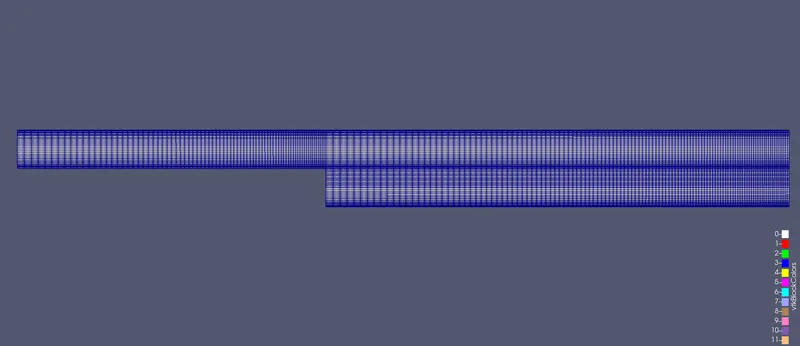
Mesh:
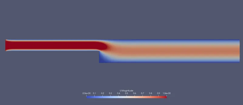
Velocity distribution:
Pressure distribution:

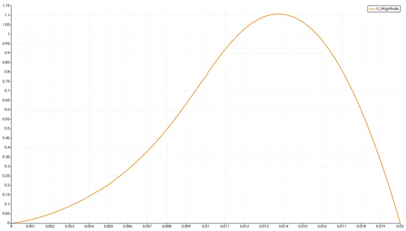
Velocity distribution at 0.085 m from the inlet:
Conclusion:
By changing the simple grading factor from the value of 0.25 to 1 the mesh becomes finer and the solution becomes very accurate.
Overall the change in the size of simple grading factor (mesh size) the results remains the same as approximately.
The execution time is lower for lower meshing grading factor