ANSA - CFD meshing on Turbocharger
Problem Statement: -
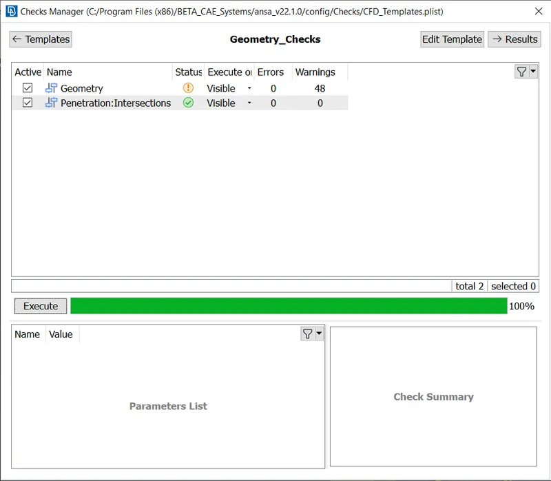
For the given model, check for the geometrical errors to make appropriate volumes. Create and assign PIDs, Perform surface mesh with the given target lengths as per PIDs.
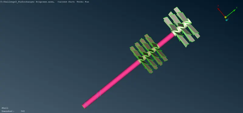
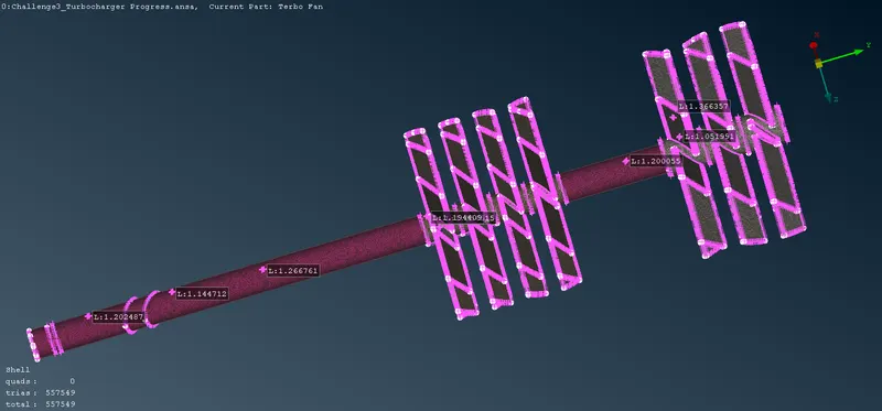
- Blade stage-1 = 1 mm
- Blade stage-2 = 1 mm
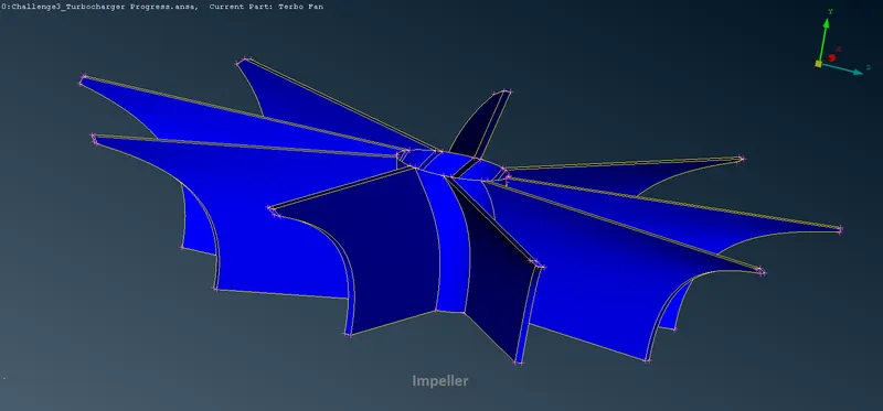
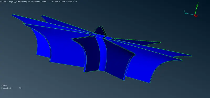
- Impeller = 2 mm
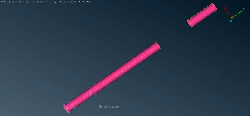
- Shaft rotor = 1 mm
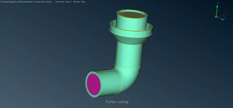
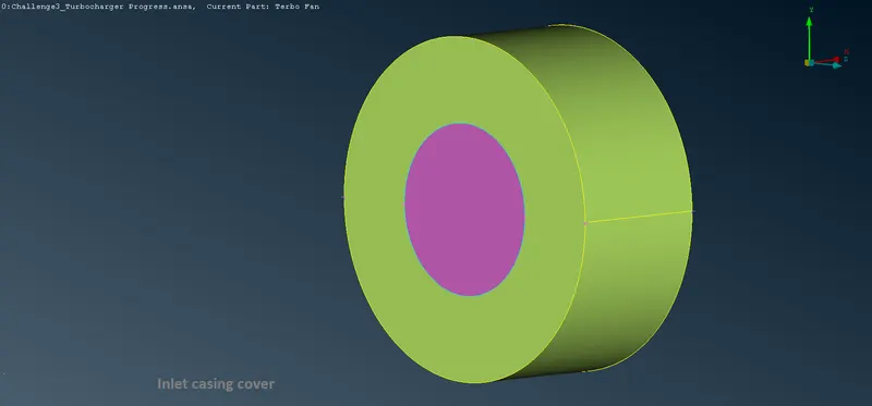
- Turbo casing = 5 mm
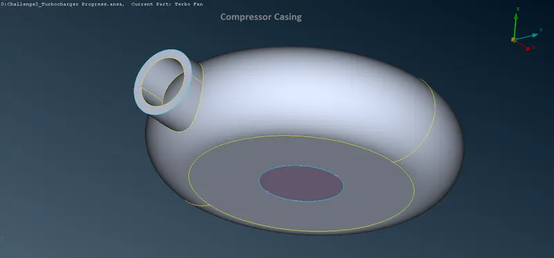
- Compressor casing = 5 mm
- Inlet casing cover = 5 mm
Perform Volumetric mesh for the required volumes
Solution: -
AIM: -
A. To Perform Geometric Cleanup of Turbo-Charger.
B. To Perform Surface and Volumetric Mesh on the Turbo-Charger at the following Mesh Parameters: -
i. Blade Stage 1 - 1mm
ii. Blade Stage 2 - 1mm
iii. Impeller - 2mm
iv. Shaft Rotor - 1mm
v. Turbo Casing - 5mm
vi. Compressor Casing - 5mm
vii. Inlet Casing Cover - 5mm
Given: -
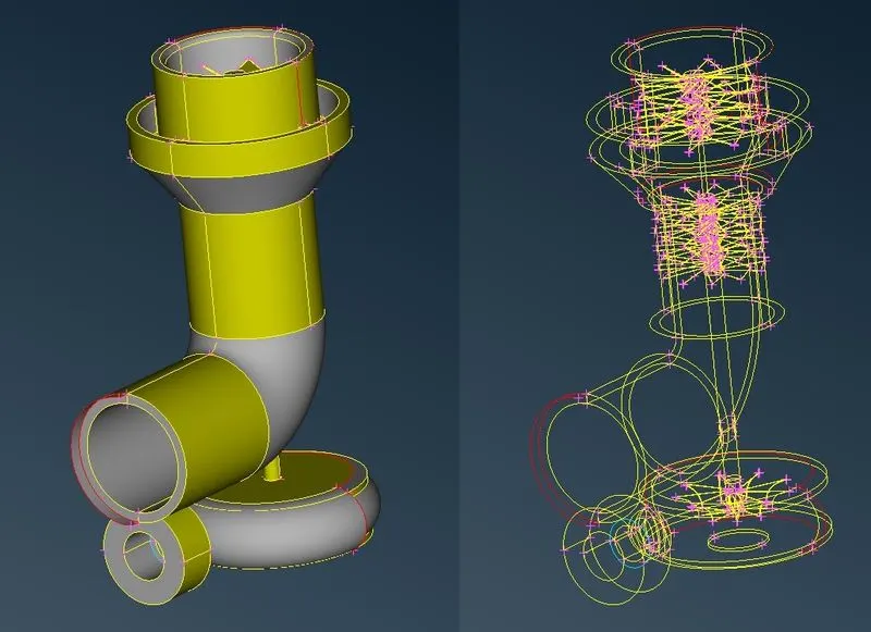
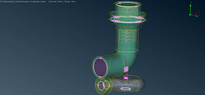
A. The Given CAD Model of Turbo-Charger is Shown Below: -
Cleaning up the Geometry: -
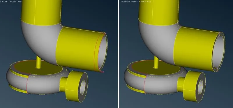
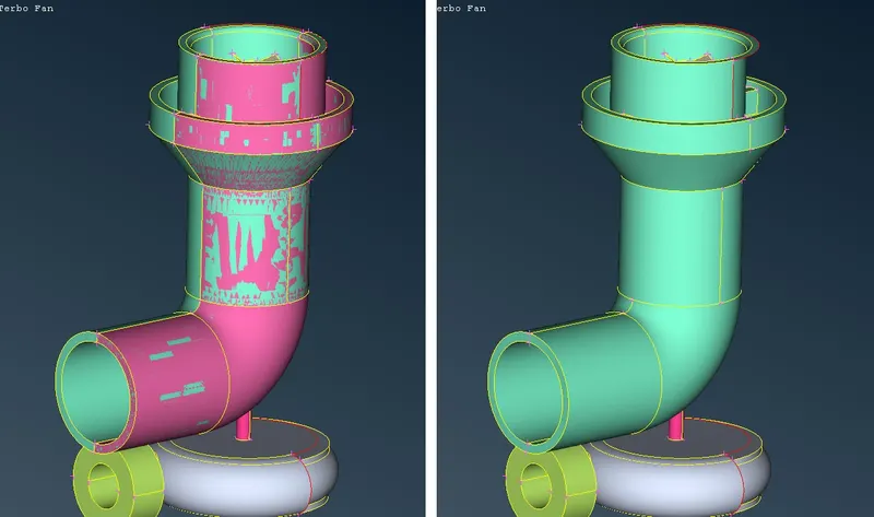
A. Performing Geometric Cleanup on Turbo Casing:-
i. Description of Tools used(Reference - ANSA Help): -
a. Project(CONS) `->` This function projects, as CONS or 3D Curves, a number of selected 3D-curves, CONS, element edges, line elements, or Hexa Box edges on a number of selected Faces, WPLANEs and CROSS_SECTIONs, in a user-controlled direction. The selection of the CONS or 3D-curves can be assisted by the 'Corner Angle', 'PID Neighbs' for line elements, or 'Path'.
b. Delete `->` The Delete function of the Geometry Group can be used to delete various ANSA entities (Curves, Faces, FE-Model entities, etc.).
c. Fill Holes(CONS) `->` This function fills holes on Faces. The holes can be of any shape. Such internal openings can be selected individually, or automatically among the visible ones if they fall below a user-specified diameter value. There is the option to create automatically 3D Curves, Points, or Connection Points of the removed holes, in order to mark their shape and position for reference.
d. Project(Hot Points) `->` This function defines a new Hot Point on a CONS, a Node on a 3D-curve, or a Weld Spot on a Face, as the projection of an existing Node, 3D-point, Hot Point, Weld Spot, etc. on each of these entities.
e. New(Faces) `->` This function defines a new surface by selecting its boundary curves and creates a corresponding face that covers the new surface. The calculated surface appears as a net.
ii. Step OUTPUT: -
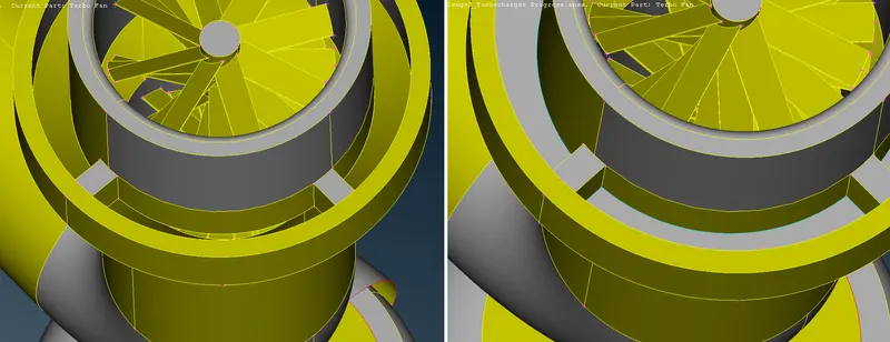
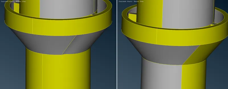
B. Performing Geometric Cleanup on Compressor Casing:-
i. Description of Tools used(Reference - ANSA Help): -
a. Copy(Transform) `->` This function is used to Translate, Rotate, Transform, Scale, Symmetry or Mirror selected entities (Faces, Points, Elements, etc). The selected entities are copied into the new position.
b. Fill Hole(CONS) `->` This function fills holes on Faces. The holes can be of any shape. Such internal openings can be selected individually, or automatically among the visible ones if they fall below a user-specified diameter value. There is the option to create automatically 3D Curves, Points, or Connection Points of the removed holes, in order to mark their shape and position for reference.
ii. Step OUTPUT: -
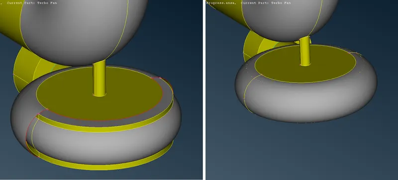
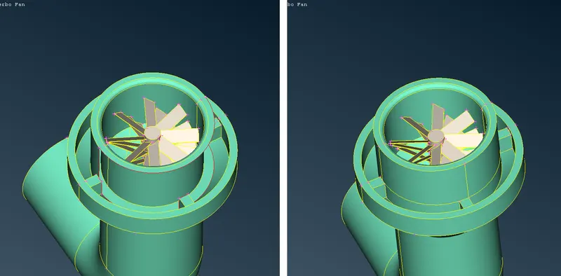
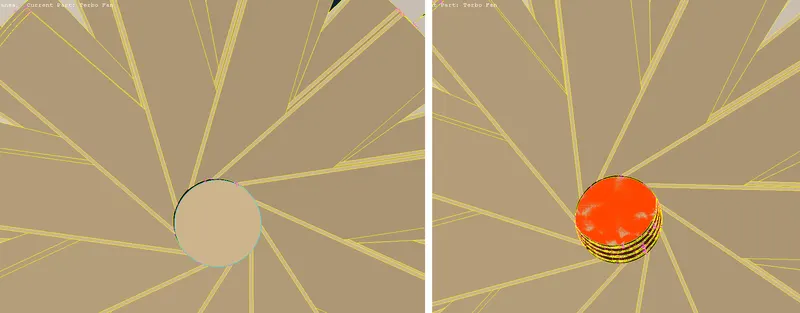
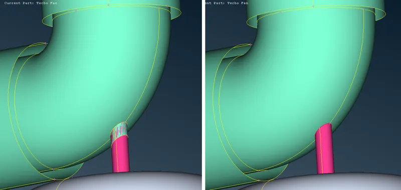
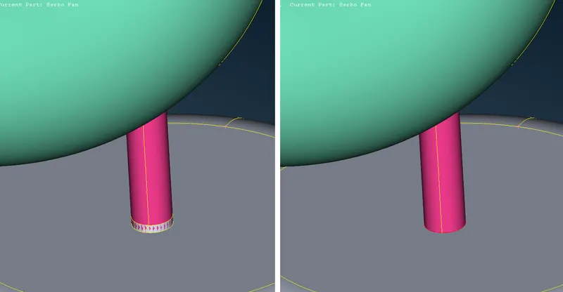
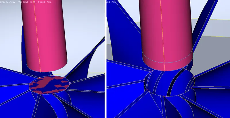
C. Performing Geometric Cleanup on Shaft, Blades, and Impeller:-
i. Description of Tools used(Reference - ANSA Help): -
a. Project(CONS) `->` This function projects, as CONS or 3D Curves, a number of selected 3D-curves, CONS, element edges, line elements, or Hexa Box edges on a number of selected Faces, WPLANEs and CROSS_SECTIONs, in a user-controlled direction. The selection of the CONS or 3D-curves can be assisted by the 'Corner Angle', 'PID Neighbs' for line elements, or 'Path'.
b. Delete `->` The Delete function of the Geometry Group can be used to delete various ANSA entities (Curves, Faces, FE-Model entities, etc.).
c. Topo(Faces) `->` This function automatically creates topological conditions between selected adjacent CONS.
ii. Step OUTPUT: -
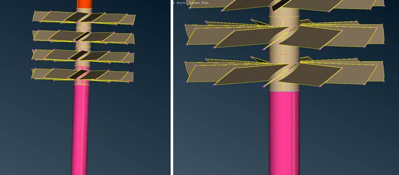
D. Filling all the Holes of the Geometry:-
i. Description of Tools used(Reference - ANSA Help): -
a. New(Faces) `->` This function defines a new surface by selecting its boundary curves and creates a corresponding face that covers the new surface. The calculated surface appears as a net.
ii. Step OUTPUT: -
Giving Property Names/PID Names: -
i. Description of Tools used(Reference - ANSA Help): -
a. Properties/PID `->` This function facilitates property management. A list of the properties existing in the file is available. Management windows, such as this one, provide filtering, sorting, and selection capabilities on the listed entities as well as the definition of new entities.
ii. PIDs
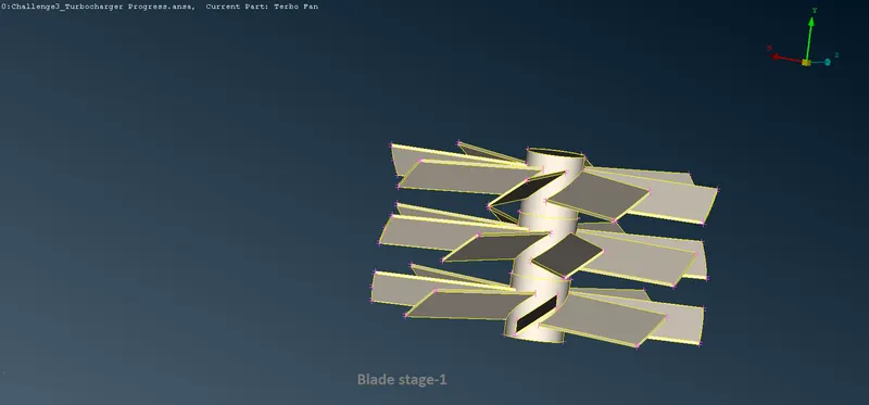
a. Blade Stage-1: -
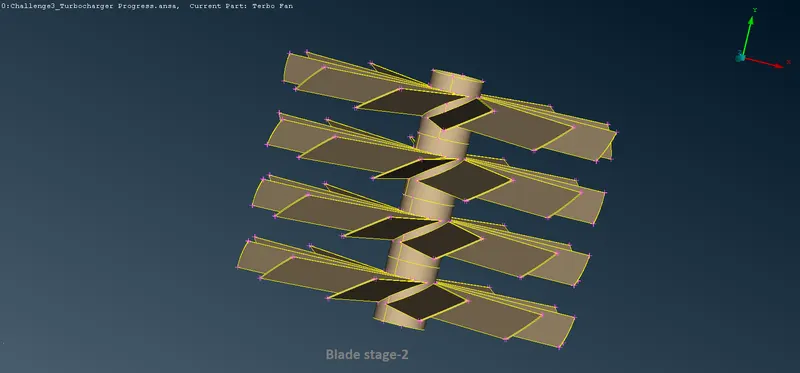
b. Blade Stage-2: -
c. Impeller: -
d. Shaft Rotor: -
e. Turbo Casing: -
f. Compressor Casing: -
g. Inlet Casing Cover: -
Creating Surface Mesh of the Components: -
A. Meshing the Shaft Rotor and Blades: -
i. Description of Tools used(Reference - ANSA Help): -
a. Join(Macros) `->` This function eliminates a Macro Area boundary segment between two adjacent Macro Areas. This way, two Macro Areas are joined to be treated as one, larger Macro Area.
b. CFD(Mesh Generation) `->` This function is recommended after the user has applied the Perimeters>Spacing(Auto CFD) on the selected perimeters.
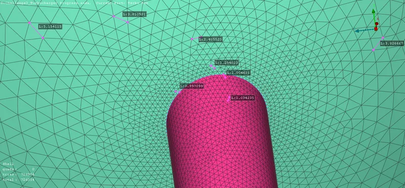
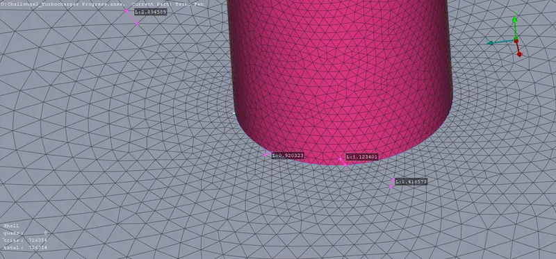
This algorithm meshes with variable element length, depending on the local curvature of the underlying CAD surface, under tight user-controlled specifications. It generated the less possible elements taking into account all small details of the geometry. This algorithm is an advanced meshing algorithm tailor-made to meet CFD specs or other application areas where a variable-size mesh is required.
ii. Step OUTPUT: -
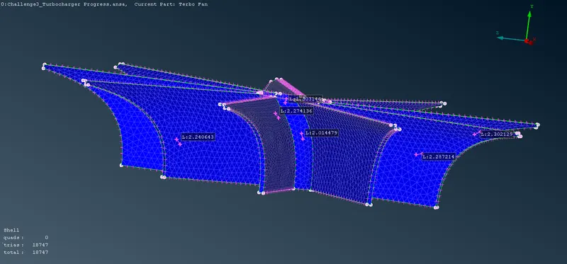
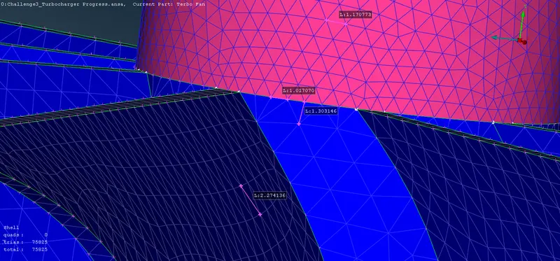
B. Meshing the Impeller: -
i. Description of Tools used(Reference - ANSA Help): -
a. Join(Macros) `->` This function eliminates a Macro Area boundary segment between two adjacent Macro Areas. This way, two Macro Areas are joined to be treated as one, larger Macro Area.
b. CFD(Mesh Generation) `->` This function is recommended after the user has applied the Perimeters>Spacing(Auto CFD) on the selected perimeters.
This algorithm meshes with variable element length, depending on the local curvature of the underlying CAD surface, under tight user-controlled specifications. It generated the less possible elements taking into account all small details of the geometry. This algorithm is an advanced meshing algorithm tailor-made to meet CFD specs or other application areas where a variable-size mesh is required.
ii. Step OUTPUT: -
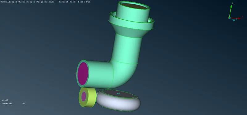
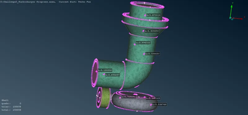
C. Meshing the Turbo Casing, Compressor Casing, and Inlet Casing Cover: -
i. Description of Tools used(Reference - ANSA Help): -
a. Join(Macros) `->` This function eliminates a Macro Area boundary segment between two adjacent Macro Areas. This way, two Macro Areas are joined to be treated as one, larger Macro Area.
b. CFD(Mesh Generation) `->` This function is recommended after the user has applied the Perimeters>Spacing(Auto CFD) on the selected perimeters.
This algorithm meshes with variable element length, depending on the local curvature of the underlying CAD surface, under tight user-controlled specifications. It generated the less possible elements taking into account all small details of the geometry. This algorithm is an advanced meshing algorithm tailor-made to meet CFD specs or other application areas where a variable-size mesh is required.
ii. Step OUTPUT: -
Creating Volume Mesh of the Components: -
A. Defining Fluid Volume: -
i. Description of Tools used(Reference - ANSA Help): -
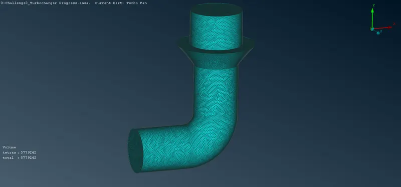
a. Define(Volumes) `->` This function automatically defines multiple volumes using already meshed macros or FE-model mesh.
b. List(Volumes) `->` This function enables the handling of the defined volumes in the database.
ii. Step OUTPUT: -
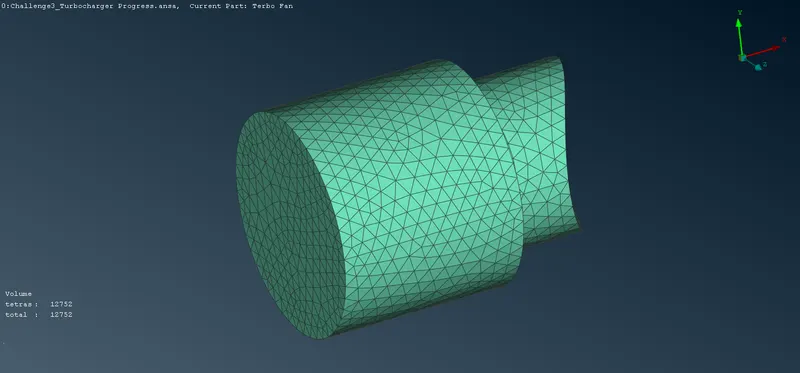
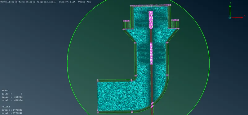
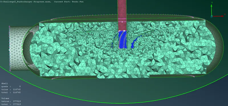
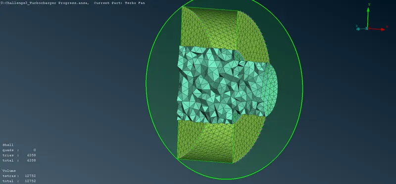
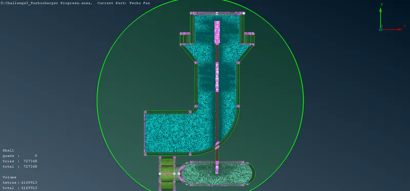
B. Meshing Fluid Volume: -
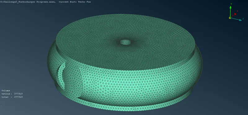
i. Description of Tools used(Reference - ANSA Help): -
a. List(Volumes) `->` This function enables the handling of the defined volumes in the database.
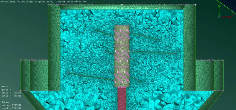
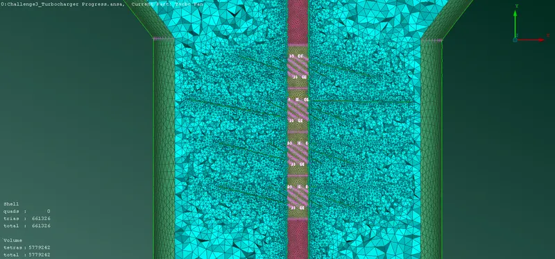
b. Cut Plane-New `->` Creates a cutting plane by defining three points and then giving the dimensions of the plane.
c. Cut Plane-List `->` Opens a window that lists all the existing cutting planes, where they can be controlled and edited.
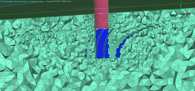
ii. Step OUTPUT: -
- Shikhar SaraswatGreat job, try to concise every project report in max 7-8 pages, it will prove fruitful ahead..!