Ansys - External flow simulation over an Ahmed body
Problem Statement: -
For the Given Ahmed's Body Perform a CFD analysis for an inlet Velocity of 25 m/sec and Generate the Appropriate Contours and Plot. Also, Calculate the Values of Drag experienced by Ahmed's Body and Perform a Grid Independence Study
Expected Results: -
1. Create a Computational domain for this analysis.
2. Perform the CFD Analysis on Ansys using the Appropriate Physics and Boundary Conditions
3. Generate the Desired Contour and Plots
4. Explain the different phenomena experienced by the Body
5. Perform the Grid Independent Study
Solution: -
AIM: -
A. To Perform Simulation on the given Amhed's Body with the Objectives to develop Velocity and Pressure Contours.
B. To calculate the drag Coefficient for the Inlet Velocity of 25 m/sec.
C. To Perform a Grid Independent Study.
Given: -
A. Ahmed's Body: -
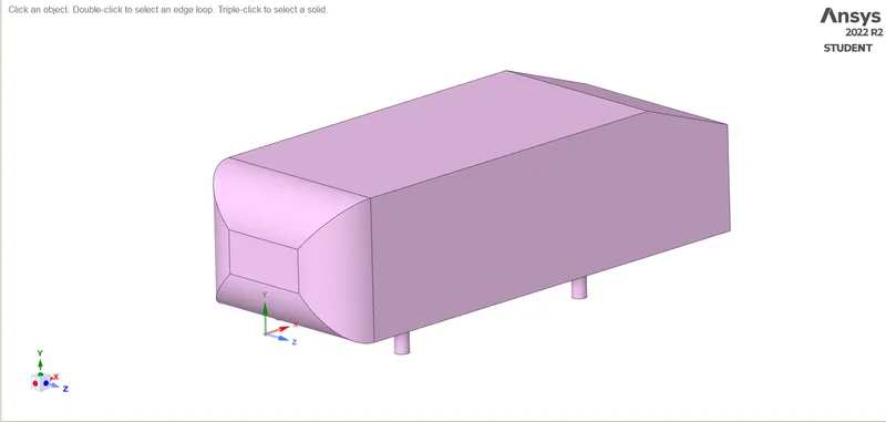
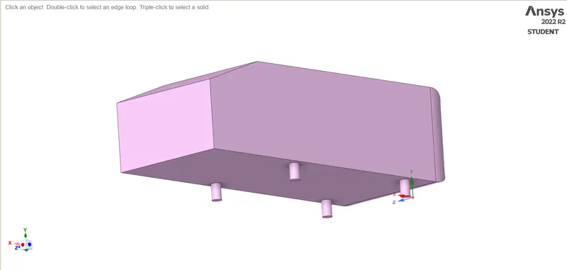
Theory: -
A. Ahmed's Body and Its Importance: -
The Ahmed Body was first created by S.R. Ahmed in his Research Paper "Some Salient Features Of The Time-Averaged Ground Vehicle Wake". This is A Blunt Body that Resembles the Generic Shape of an Automobile and since its creation, it is highly used to validate Simulation Tools. This Geometry has gone through real-world Testing due to which there is real-world data available for drag, lift, Velocity Profile, Pressure Profile, etc.
The Following are the Importance of The Ahmed Body: -
i. For the given geometry there is real-world Data available for Validating Simulation Tools.
ii. The Geometry Resembles the Generic Shape of an Automobile which gives a real-world idea of the behavior of the Wake Region of an Automobile.
B. Y+ in CFD: -
In a Turbulent Flow Condition, the domain of the fluid layer affected by the Viscous effect is small but very significant and these Viscous effects are very dominant in a very small region of flow from the Walls. To capture these Viscous Effects with high accuracy the Y+ Boundary layer is used.
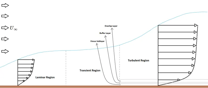
Fig.1 Diagram Represents Flow over A flat Plate(This image is inspired/Re-created from Fluid Mechanics: Fundamentals and Application, author Y. Cengel for study purpose only and with no intention to infringe the Copyright of the original Author and/or the Publication)
Y+ is a Dimension-less Number that is used to determine the thickness of the mesh layer just over the Solid Body so that the flow parameters are calculated with high accuracy.
`y+ = (rhou_(tau)triangley)/mu`
Now,
As `v = mu/rho`
`=> y+ = (rhou_(tau)triangley)/mu or (u_(tau)triangley)/v`
where, `rho ->` Density of Fluid
`u_(tau) ->` Shear Velocity
`triangley ->` Boundary Layer Thickness at that Location
`mu ->` Dynamic Viscosity
`v ->` Kinematic Viscosity
Steps to Setup the External Flow Over an Ahmed Body: -
A. Setting up the Ansys Workbench: -
Ansys Workbench `->` ToolBox `->` Analysis System `->` `ubrace("Fluid Flow(Fluent)")_("Selecting" -> "Holding" -> "Dragging and Drooping to Project Schematic")`
B. Opening SpaceClaim Geometry and Creating Computational Domain: -
i. Steps to Open SpaceClaim: -
Ansys Workbench `->` Project Schematic `->` Project `->` Geometry `->` Right-Click `->` Select SpaceClaim Geometry
ii. Steps to Load the Ahmed Body Geometry: -
SpaceClaim `->` File `->` Open
iii. Steps to Create Computational Domain: -
a. Outer Enclosure: SpaceClaim `->` Prepare `->` Enclosure `->` `ubrace("Give the Required Dimensions of the Enclosure")_("In our case, Length Ahead = 1500mm, Length Behind = 4000mm, Width on Either Side = 500mm, Height Below = 0mm, Height Above = 900mm")`
b. Inner Enclosure: SpaceClaim `->` Prepare `->` Enclosure `->` `ubrace("Give the Required Dimensions of the Enclosure")_("In our case, Length Ahead = 500mm, Length Behind = 1000mm, Width on Either Side = 220mm, Height Below = 0mm, Height Above = 400mm")`
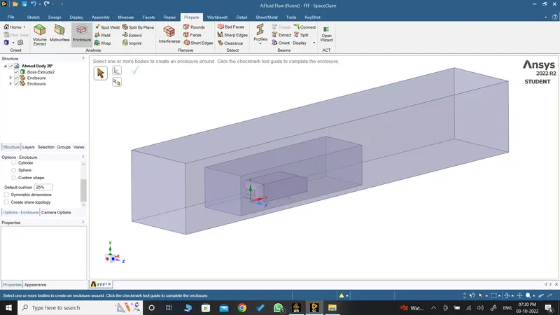
Fig.2 Ahmed Body With Inner and Outer Computational Domain
iv. Steps to Remove Interference and create Share Topology between the Domains: -
a. Removing Interference: SpaceClaim `->` Prepare `->` `ubrace("Interference")_("It will auto-detect the interference")` `->` Enter
b. Share Topology: SpaceClaim `->` Workbench `->` `ubrace("Share")_("It will auto-detect the Common Boundaries")` `->` Enter
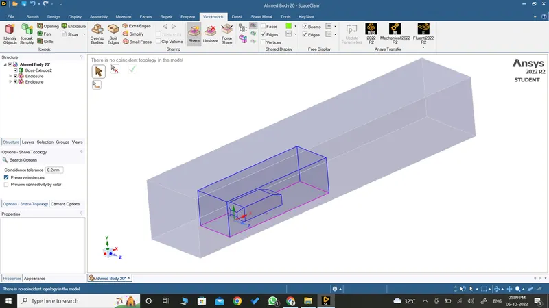
Fig.3 Ahmed Body With Shared Topology of Boundaries and Ahmed Body
v. (Used for Splitting the Body When Needed)Steps to Split the Given Body and Enclosure: -
a. Creating Planes: SpaceClaim `->` Design `->` Plane `->` Select the Origin Point
b. Splitting Body: SpaceClaim `->` Design `->` Split Body `->` Box Select Enclosures and Body `->` Select the XY Plane For Splitting along that `->` Select "Select Region to Remove" `->` Select One-Half of the Bodies
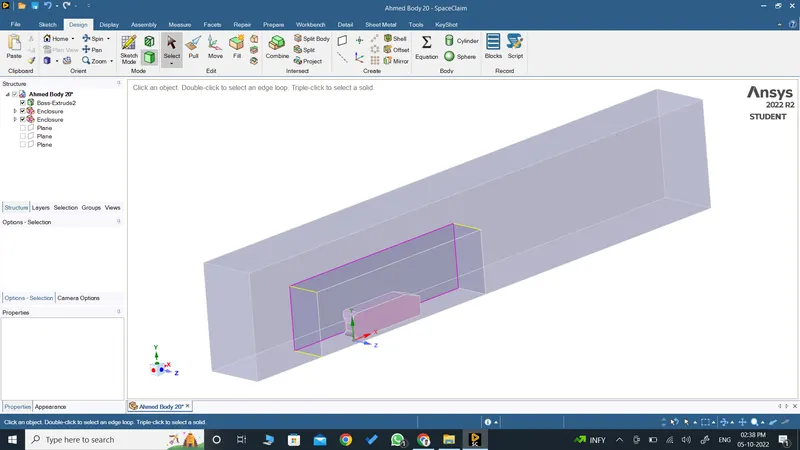
Fig.4 Splitted Ahmed Body With Shared Topology of Boundaries and Ahmed Body
C. Opening Mechanical(Meshing) and Meshing the Geometry: -
i. Steps to Open Meshing: -
Ansys Workbench `->` Project Schematic `->` Project `->` Mesh `->` Right-Click `->` Edit
ii. Steps to Name the Boundary: -
Mechanical(Meshing) `->` Model Working Window `->` Select the Boundary `->` Click N `->` Give the desired Name `->` Enter
a. Full Ahmed Body and Computational Domain: -
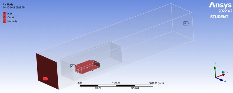
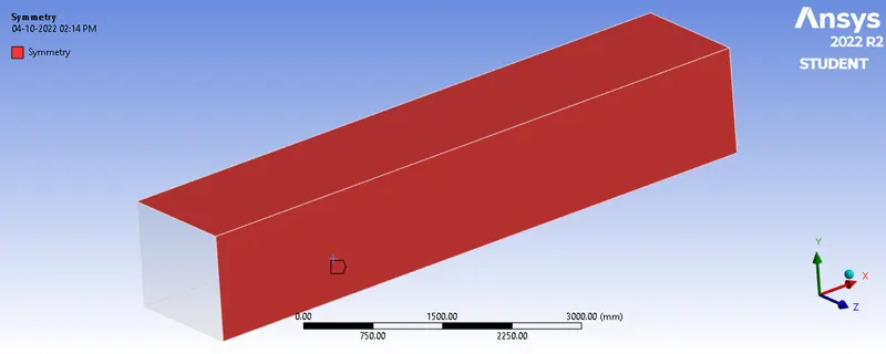
Fig.5 Naming of Ahmed Body with Computational Domain
b. Splitted Ahmed Body and Computational Domain: -
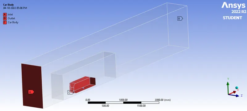
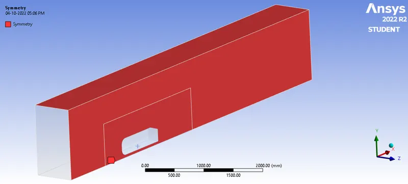
Fig.6 Naming of Splitted Ahmed Body with Computational Domain
iii. Steps to Create the Mesh: -
a. Setting Base Mesh Size: Outline Window `->` Select Mesh `->` Details of Mesh Window `->` Defaults `->` Element Size is set to "100mm"
b. Creating Multizone Mesh: `ubrace("Select the Desired Geometry")_("Select the Outer Enclosure")` `->` Mesh `->` Right-Click `->` Select "Method" from Insert `->` `ubrace("Select the desired Mesh Parameters")_("In our Case for the Selected Geometry Select Multizone Meshing")`
c. Meshing the Inner Enclosure: `ubrace("Select the Desired Geometry")_("Select the Inner Enclosure")` `->` Mesh `->` Right-Click `->` Select "Sizing" from Insert `->` `ubrace("Select the desired Mesh Parameters")_("In our Case for the Selected Geometry Define mesh Size")`
d. Meshing the Ahmed Body Legs: `ubrace("Select the Desired Geometry")_("Select the Ahmed Body's Legs Surface")` `->` Mesh `->` Right-Click `->` Select "Sizing" from Insert `->` `ubrace("Select the desired Mesh Parameters")_("In our Case for the Selected Geometry Define mesh Size as 20mm")`
e. Creating Inflation Layer: Outline Window `->` Select Mesh `->` Details of Mesh Window `->` Inflation `->`Select "All Faces in Chosen Named Selection" from Use Automatic Inflation `->` Select "Car Body" from Named Selection `->` Select "First Layer Inflation" from Inflation Option `->` Define First Layer Thickness to 0.4mm `->` Define Maximum Layers to 10
`->` Mesh Size of Base Mesh-Inner Enclosure-Ahmed Body Leg: 100-50-5
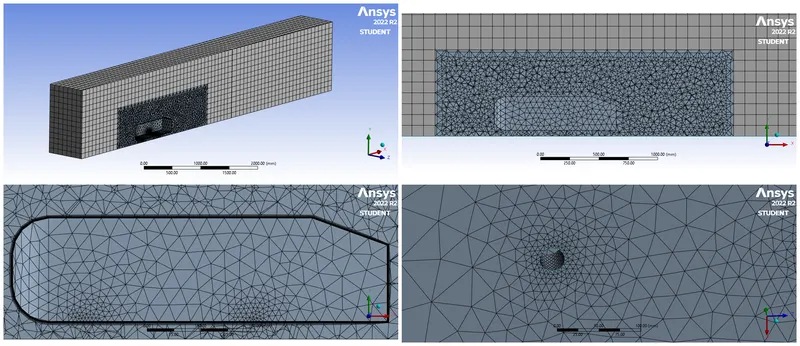
Fig.7 Images of Meshed Geometry 100-50-5
`->` Mesh Size of Base Mesh-Inner Enclosure-Ahmed Body Leg: 100-30-3
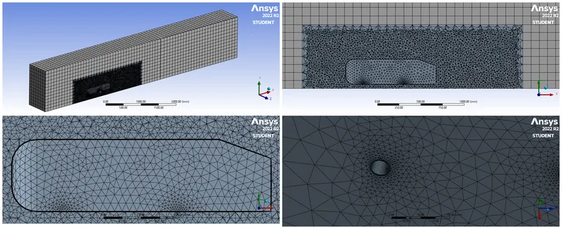
Fig.8 Images of Meshed Geometry 100-30-3
`->` Mesh Size of Base Mesh-Inner Enclosure-Ahmed Body Leg: 100-25-2.5
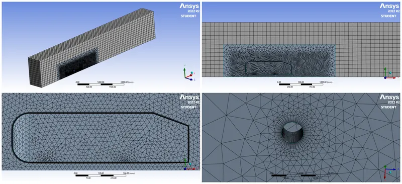
Fig.9 Images of Meshed Geometry 100-25-2.5
`->` Mesh Size of Base Mesh-Inner Enclosure-Ahmed Body Leg: 100-22-5
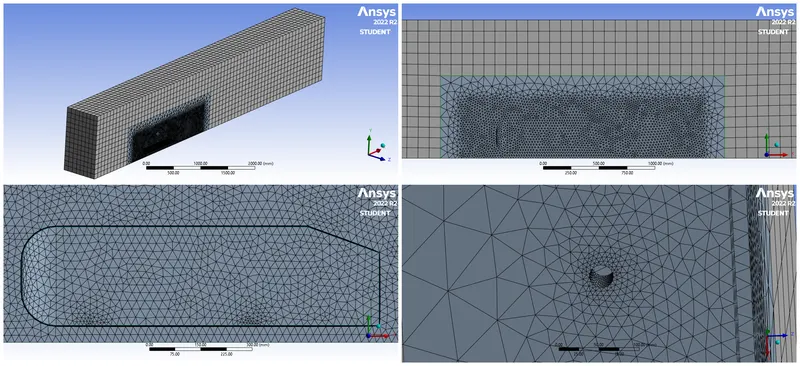
Fig.10 Images of Meshed Geometry 100-22-5
D. Setuping the Physics and Boundary Conditions: -
i. Steps to Open Ansys Fluent: -
Ansys Workbench `->` Project Schematic `->` Project `->` Setup `->` Right-Click `->` Edit
ii. Steps to Check Mesh: -
Fluent `->` Outline View Window `->` Setup `->` General `->` Mesh `->` Check
iii. Steps to Set up the Physics: -
Fluent `->` Physics `->` Models `->` Viscous `->` `ubrace("Select Desired Viscous Model")_("In our case Select K-Epsilon standard With Enhanced Wall Treatment")`
iv. Steps to Set up Boundary Condition: -
Fluent `->` Physics `->` Zone `->` Boundaries `->` Select the desired Component `->` Select the Desired Type for that Component `->` Edit `->` Add the Values for the Component `->` Apply & Close
v. Steps to Set up Reports: -
Fluent `->` Solution `->` Reports `->` Definition `->` New `->` Select the Desired Report `->` Rename the Report `->` Change the Field Variable to Desired Variable `->` Select the desired Surface `->` Ok
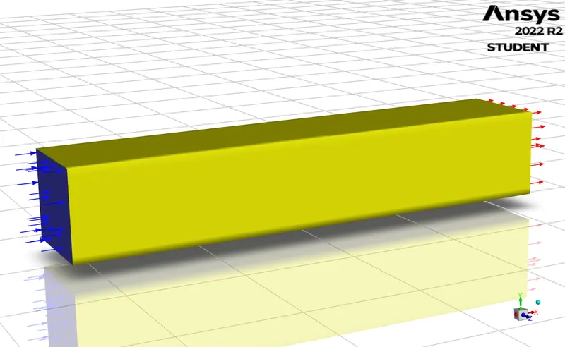
Fig.11 Opening Meshed Admed Body with Computational Domain in Fluent
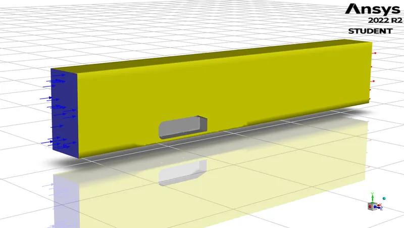
Fig.12 Opening Meshed Splitted Admed Body with Computational Domain in Fluent
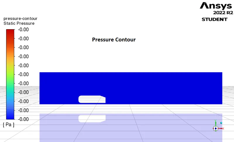
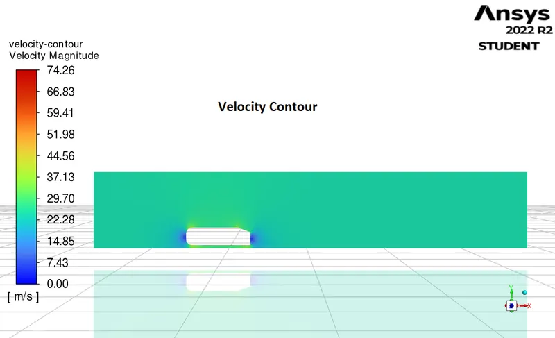
Fig.13 Initial Velocity and Pressure Contours
E. Performing Calculations and Developing Solutions: -
i. Steps to Perform Calculations: -
a. Initializing the Initial Conditions: Fluent `->` Solution `->` Initialization `->` Initialize
b. Setting up no. of Iterations: Fluent `->` Solution `->` Run Calculations `->` Setting Desired Iterations in "No. of Iterations"
c. Running Calculations: Fluent `->` Solution `->` Run Calculations `->` Calculate
`->` Calculations Plots of 100-50-5
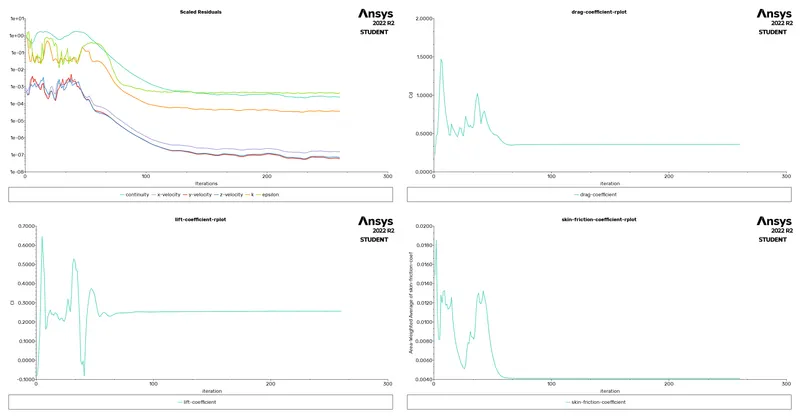
Fig.14 Solution Outputs of 100-50-5
`->` Calculations Plots of 100-30-3
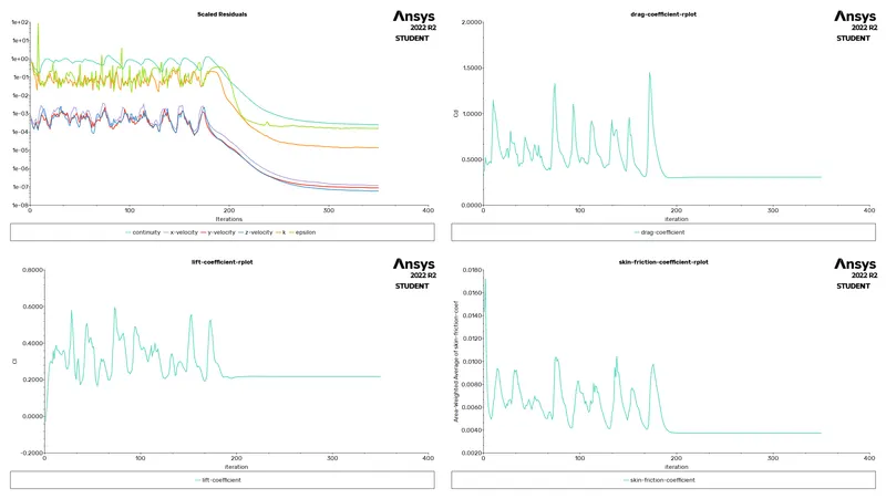
Fig.15 Solution Outputs of 100-30-3
`->` Calculations Plots of 100-25-2.5
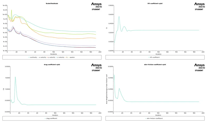
Fig.16 Solution Outputs of 100-25-2.5
`->` Calculations Plots of 100-22-5
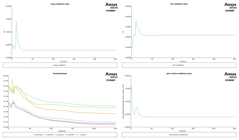
Fig.17 Solution Outputs of 100-22-5
ii. Steps to Create desired Solution Outputs: -
Fluent `->` Results `->` Graphics `->` Select the Desired Plots and set the parameters
`->` Graphical Solutions of 100-50-5
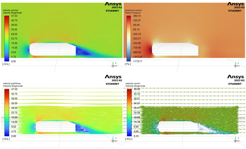
Fig.18 Graphical Solution Outputs of 100-50-5
`->` Graphical Solutions of 100-30-3
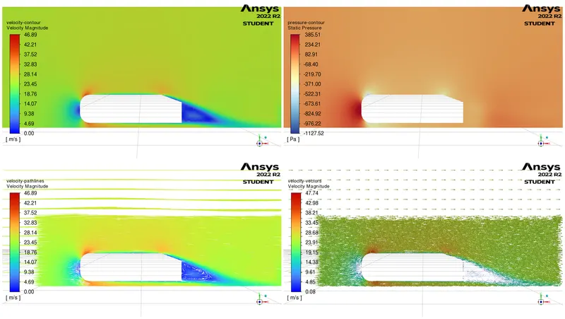
Fig.19 Graphical Solution Outputs of 100-30-3
`->` Graphical Solutions of 100-25-2.5
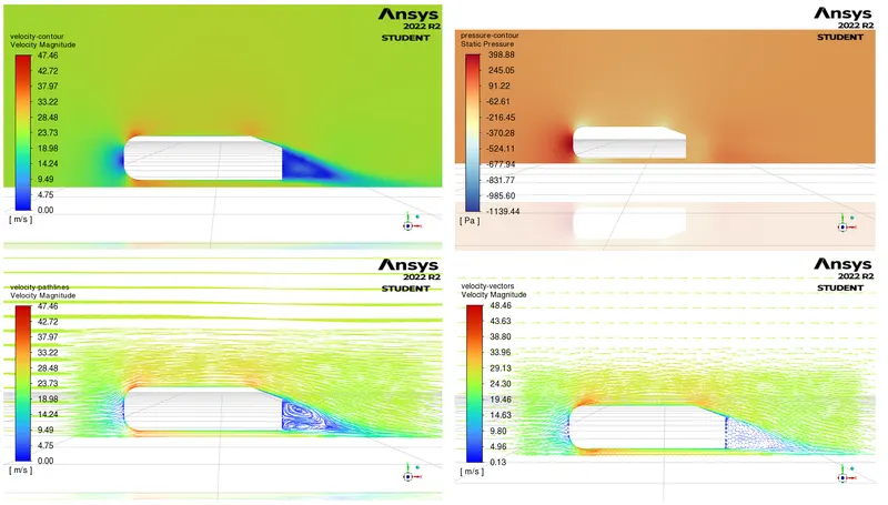
Fig.20 Graphical Solution Outputs of 100-25-2.5
`->` Graphical Solutions of 100-22-5
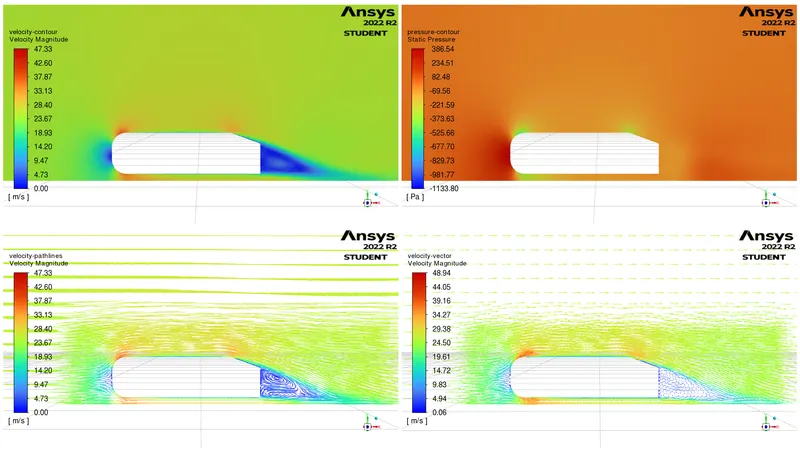
Fig.21 Solution Outputs of 100-22-5
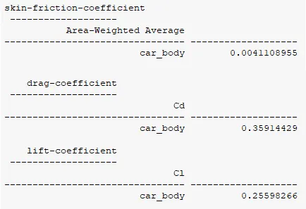
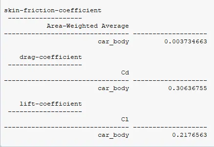
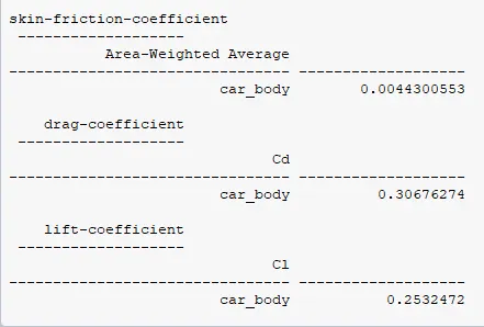
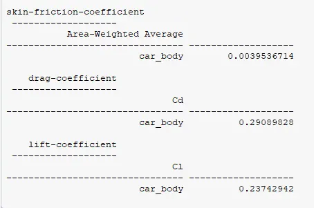
`->` Numerical Solutions
 |
 |
 |
 |
| Results from 100-50-5 | Results from 100-30-3 | Results from 100-25-2.5 | Results from 100-22-5 |
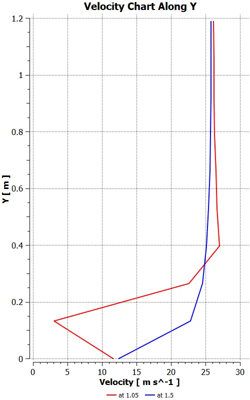
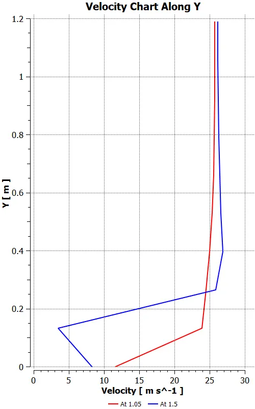
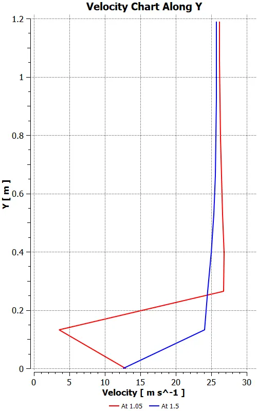
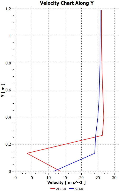
`->` Velocity Along Y at 1.05m and 1.5m from Origin in X direction
 |
 |
 |
 |
| Results from 100-50-5 | Results from 100-30-3 | Results from 100-25-2.5 | Results from 100-22-5 |
Observations and their Reasons: -
A. Point of Separation and Wake Region: -
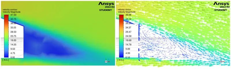
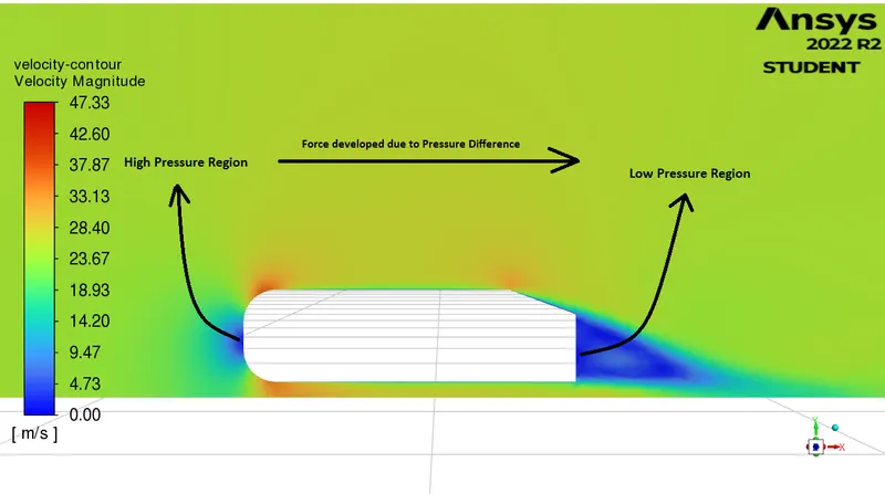
The Point on the Solid Body beyond which the Boundary layer separates from the Solid Body is termed the Point of Separation. The viscous region that is closer to the wall while separation still remains dominant in viscous effects which leads to the formation of slow-moving highly viscous fluid behind the body and that creates a lower pressure region which due to high pressure in the front and low pressure at the rear develops Drag on the body. This low pressure and High Viscous Separated Region Developed Behind the Body is Called Wake Region.
B. Drag Obtained from different Grid Size: -
The drag results generated from the 100-50-5 Meshing produce a few inaccurate results due to course mesh but when the inner Enclosure is meshed with a size of 30mm and below it starts to converge to similar values of Drag. From this, it could be concluded that the Grid size if taken below the 30mm mesh size will generate the same results.
So among these cases, the grid independence is achieved at a 30mm mesh size.