ANSA - CFD Meshing for BMW car
Problem Statement: -
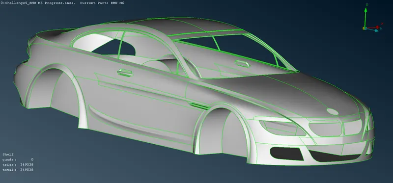
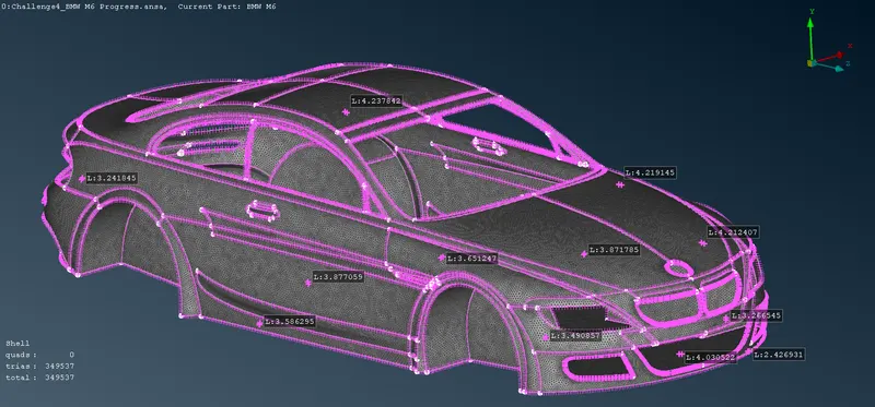
For the given model, check and solve all geometrical errors and Assign appropriate PIDs. Perform meshing with the given Target length and element Quality criteria. Create A wind Tunnel for analysis and Assign appropriate PIDs.
The target lengths for all PIDs are given below: -
1. Body - 3mm
2. Lights - 4mm
3. Grills - 1mm
4. Rims and Tires - 2mm
5. Optical Rear View Mirror - 2mm
6. Windows - 2mm
7. Silencers - 3mm
8. Logo - 1mm
Solution: -
1. AIM: -
A. To Perform Geometric Cleanup of BMW M6 Model and assign Relevant PIDs
B. To Perform Surface Mesh on the BMW M6 Model at the following Mesh Parameters: -
i. Body - 3mm
ii. Lights - 4mm
iii. Grills - 1mm
iv. Rims and Tyres - 2mm
2. Given: -
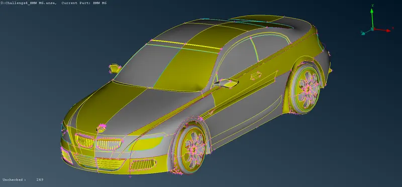
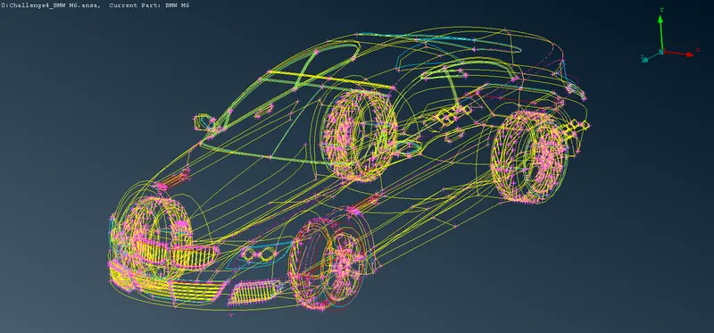
A. The Given CAD Model of the BMW M6 Model is Shown Below: -
3. Smoothening the Surfaces and Deleting Half the Model: -
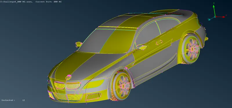
A. Smoothening the Surfaces: -
i. Description of Tools used(Reference - ANSA Help): -
a. Length(Perimeters) `->` This function defines the element length on selected perimeter segments or macro areas. The element length may be explicitly declared or may be declared as a factor to be multiplied by the existing element length.
ii. Step OUTPUT: -
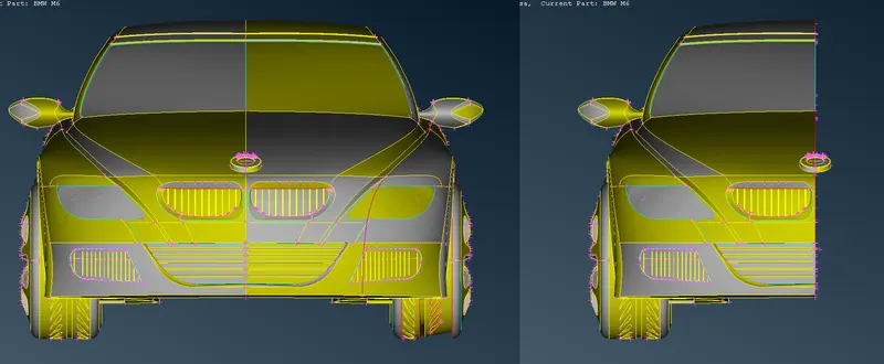
B. Deleting Half the Car Model: -
i. Description of Tools used(Reference - ANSA Help): -
a. Delete `->` The Delete function of the Geometry Group can be used to delete various ANSA entities (Curves, Faces, FE-Model entities, etc.).
ii. Step OUTPUT: -
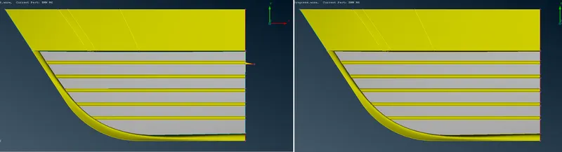
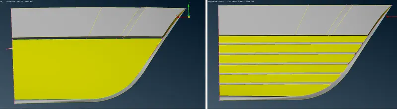
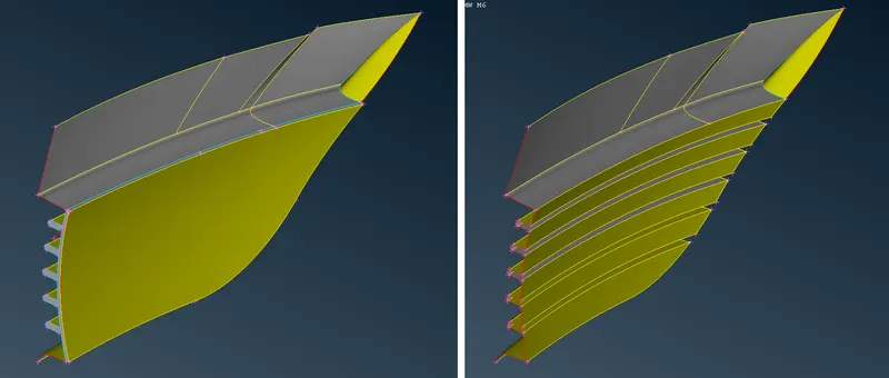
4. Performing Geometric Cleanup of Grills: -
A. Cleaning Lower Grill: -
i. Description of Tools used(Reference - ANSA Help): -
a. Not `->` Hide one or more selected entities.
b. Delete `->` The Delete function of the Geometry Group can be used to delete various ANSA entities (Curves, Faces, FE-Model entities, etc.).
c. Project(CONS) `->` This function projects, as CONS or 3D Curves, a number of selected 3D-curves, CONS, element edges, line elements, or Hexa Box edges on a number of selected Faces, WPLANEs, and CROSS_SECTIONs, in a user-controlled direction. The selection of the CONS or 3D-curves can be assisted by the 'Corner Angle', 'PID Neighbs' for line elements, or 'Path'.
d. New(Faces) `->` This function defines a new surface by selecting its boundary curves and creates a corresponding face that covers the new surface. The calculated surface appears as a net.
e. Cut(Faces) `->` This function cuts (splits) an existing Face or joins faces if an inverse operation is applied (right mouse button). It does not require the existence of Hot Points since it can be applied directly on an arbitrary position of a CONS.
f. Topo(Faces) `->` This function automatically creates topological conditions between selected adjacent CONS.
g. Delete(Hot Points) `->` This function deletes Hot Points lying on a CONS segment. After deletion, the adjacent CONS segments sharing the Hot Point become one.
ii. Step OUTPUT: -
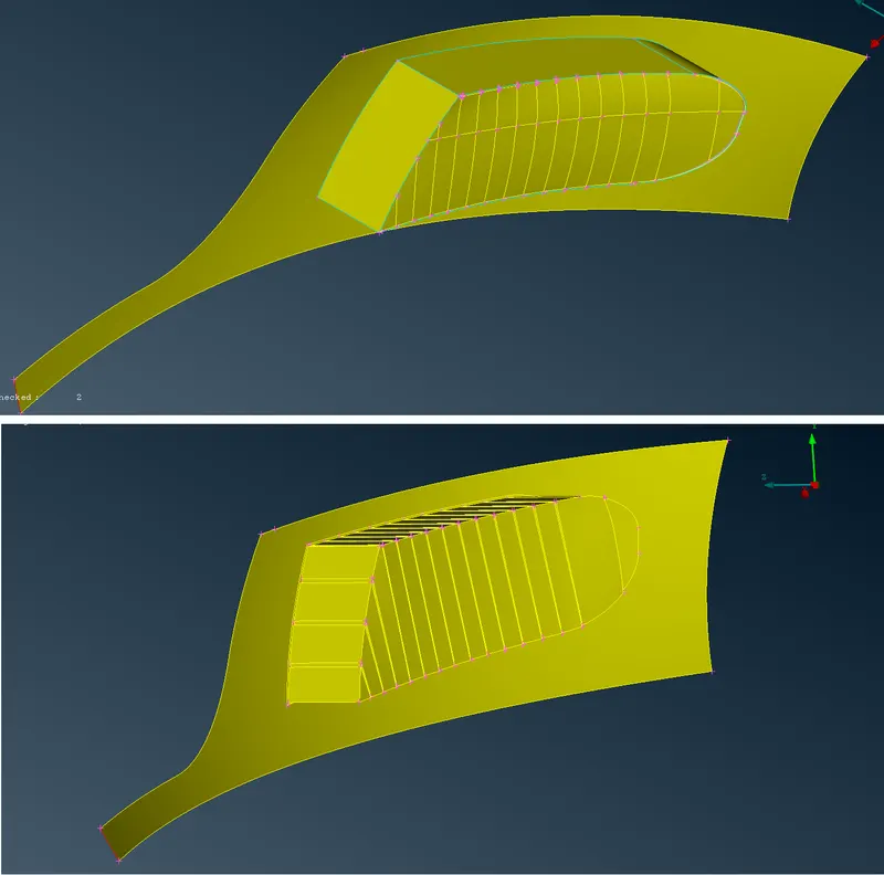
B. Cleaning Side Grill: -
i. Description of Tools used(Reference - ANSA Help): -
a. Not `->` Hide one or more selected entities.
b. Delete `->` The Delete function of the Geometry Group can be used to delete various ANSA entities (Curves, Faces, FE-Model entities, etc.).
c. Project(CONS) `->` This function projects, as CONS or 3D Curves, a number of selected 3D-curves, CONS, element edges, line elements, or Hexa Box edges on a number of selected Faces, WPLANEs, and CROSS_SECTIONs, in a user-controlled direction. The selection of the CONS or 3D-curves can be assisted by the 'Corner Angle', 'PID Neighbs' for line elements, or 'Path'.
d. New(Faces) `->` This function defines a new surface by selecting its boundary curves and creates a corresponding face that covers the new surface. The calculated surface appears as a net.
e. Cut(Faces) `->` This function cuts (splits) an existing Face or joins faces if an inverse operation is applied (right mouse button). It does not require the existence of Hot Points since it can be applied directly on an arbitrary position of a CONS.
f. Topo(Faces) `->` This function automatically creates topological conditions between selected adjacent CONS.
g. Delete(Hot Points) `->` This function deletes Hot Points lying on a CONS segment. After deletion, the adjacent CONS segments sharing the Hot Point become one.
ii. Step OUTPUT: -
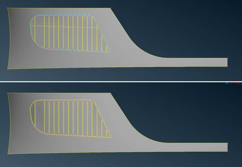
C. Cleaning Upper Grill: -
i. Description of Tools used(Reference - ANSA Help): -
a. Not `->` Hide one or more selected entities.
b. Delete `->` The Delete function of the Geometry Group can be used to delete various ANSA entities (Curves, Faces, FE-Model entities, etc.).
c. Project(CONS) `->` This function projects, as CONS or 3D Curves, a number of selected 3D-curves, CONS, element edges, line elements, or Hexa Box edges on a number of selected Faces, WPLANEs, and CROSS_SECTIONs, in a user-controlled direction. The selection of the CONS or 3D-curves can be assisted by the 'Corner Angle', 'PID Neighbs' for line elements, or 'Path'.
d. Proj.Cut(Faces) `->` This function is used to cut (split) a Face by combining the Hot Points>Project and Faces>Cut functions. In other words, it splits a face between a selected hot point and its projection on a selected CONS.
e. New(Faces) `->` This function defines a new surface by selecting its boundary curves and creates a corresponding face that covers the new surface. The calculated surface appears as a net.
f. Cut(Faces) `->` This function cuts (splits) an existing Face or joins faces if an inverse operation is applied (right mouse button). It does not require the existence of Hot Points since it can be applied directly on an arbitrary position of a CONS.
g. Topo(Faces) `->` This function automatically creates topological conditions between selected adjacent CONS.
h. Delete(Hot Points) `->` This function deletes Hot Points lying on a CONS segment. After deletion, the adjacent CONS segments sharing the Hot Point become one.
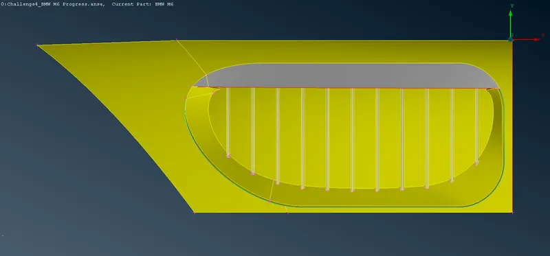
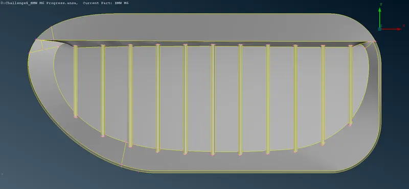
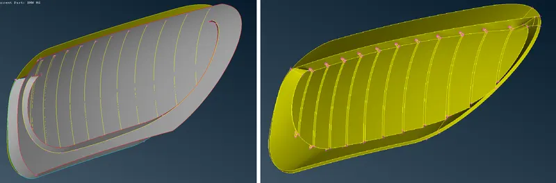
ii. Step OUTPUT: -
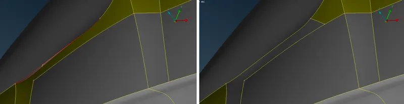
5. Performing Geometric Cleanup of Lights: -
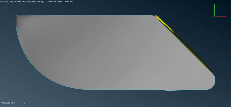
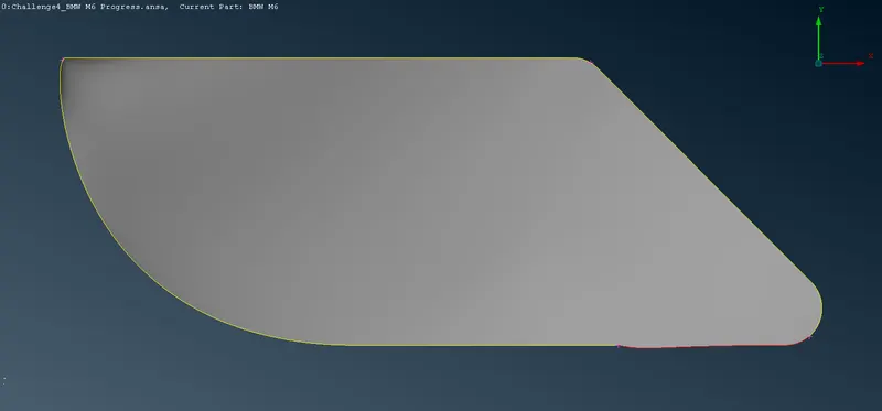
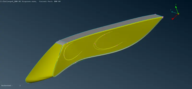
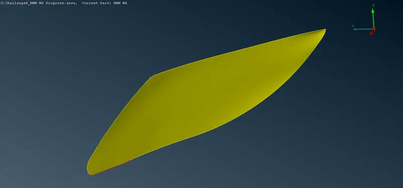
A. Cleaning HeadLight: -
i. Description of Tools used(Reference - ANSA Help): -
a. Not `->` Hide one or more selected entities.
b. Delete `->` The Delete function of the Geometry Group can be used to delete various ANSA entities (Curves, Faces, FE-Model entities, etc.).
c. Topo(Faces) `->` This function automatically creates topological conditions between selected adjacent CONS.
ii. Step OUTPUT: -
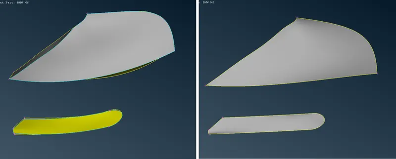
B. Cleaning TailLights: -
i. Description of Tools used(Reference - ANSA Help): -
a. Not `->` Hide one or more selected entities.
b. Delete `->` The Delete function of the Geometry Group can be used to delete various ANSA entities (Curves, Faces, FE-Model entities, etc.).
c. Topo(Faces) `->` This function automatically creates topological conditions between selected adjacent CONS.
ii. Step OUTPUT: -
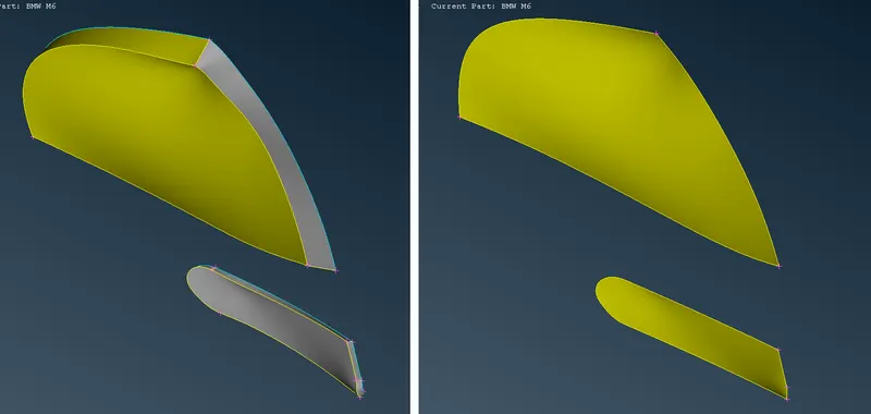
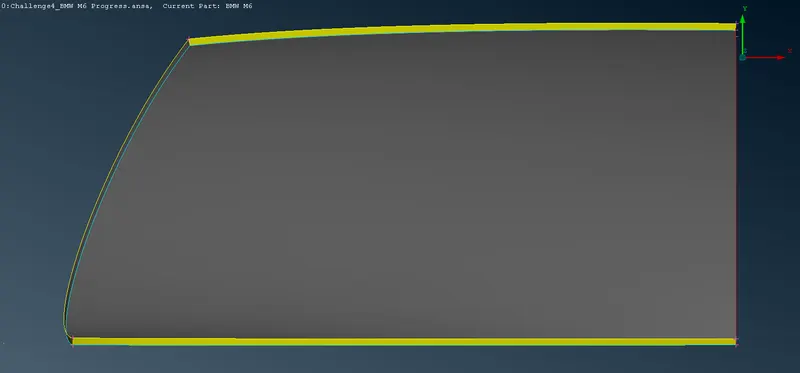
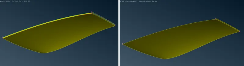
6. Performing Geometric Cleanup of Windows and Optical Rear View Mirror: -
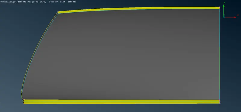
A. Cleaning Windshield: -
i. Description of Tools used(Reference - ANSA Help): -
a. Not `->` Hide one or more selected entities.
b. Delete `->` The Delete function of the Geometry Group can be used to delete various ANSA entities (Curves, Faces, FE-Model entities, etc.).
c. Topo(Faces) `->` This function automatically creates topological conditions between selected adjacent CONS.
ii. Step OUTPUT: -
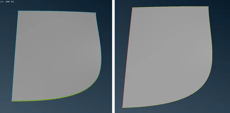
B. Cleaning Rear Windshield: -
i. Description of Tools used(Reference - ANSA Help): -
a. Not `->` Hide one or more selected entities.
b. Delete `->` The Delete function of the Geometry Group can be used to delete various ANSA entities (Curves, Faces, FE-Model entities, etc.).
c. Topo(Faces) `->` This function automatically creates topological conditions between selected adjacent CONS.
ii. Step OUTPUT: -
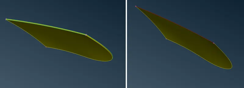
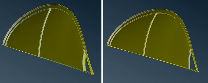
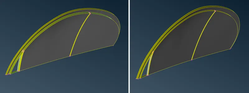
C. Cleaning Door Windows: -
i. Description of Tools used(Reference - ANSA Help): -
a. Not `->` Hide one or more selected entities.
b. Delete `->` The Delete function of the Geometry Group can be used to delete various ANSA entities (Curves, Faces, FE-Model entities, etc.).
c. Topo(Faces) `->` This function automatically creates topological conditions between selected adjacent CONS.
ii. Step OUTPUT: -
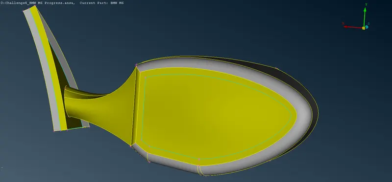
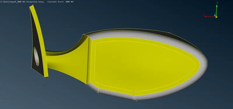
D. Cleaning Optical Rear View Mirror: -
i. Description of Tools used(Reference - ANSA Help): -
a. Not `->` Hide one or more selected entities.
b. Delete `->` The Delete function of the Geometry Group can be used to delete various ANSA entities (Curves, Faces, FE-Model entities, etc.).
c. Topo(Faces) `->` This function automatically creates topological conditions between selected adjacent CONS.
d. New(Faces) `->` This function defines a new surface by selecting its boundary curves and creates a corresponding face that covers the new surface. The calculated surface appears as a net.
ii. Step OUTPUT: -
7. Performing Geometric Cleanup of Silencer, Logo, Rims and Tyres: -
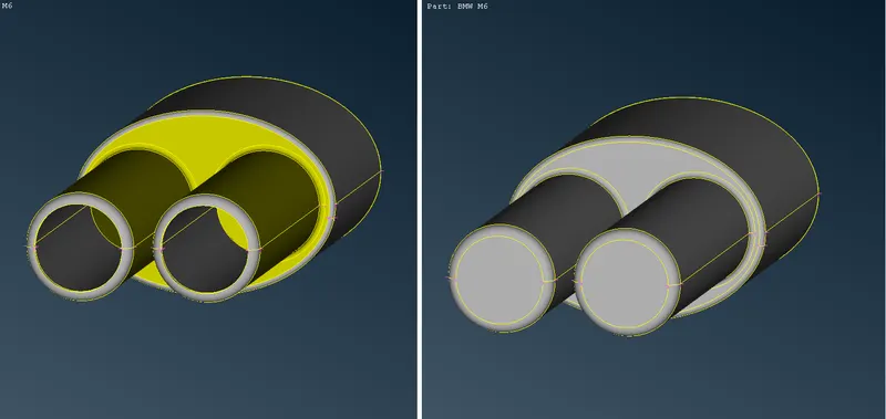
A. Cleaning Silencer: -
i. Description of Tools used(Reference - ANSA Help): -
a. Not `->` Hide one or more selected entities.
b. Delete `->` The Delete function of the Geometry Group can be used to delete various ANSA entities (Curves, Faces, FE-Model entities, etc.).
c. Release(CONS) `->` This function releases CONS that have been automatically joined (pasted) or were joined by the CONS>Paste function.
d. New(Faces) `->` This function defines a new surface by selecting its boundary curves and creates a corresponding face that covers the new surface. The calculated surface appears as a net.
ii. Step OUTPUT: -
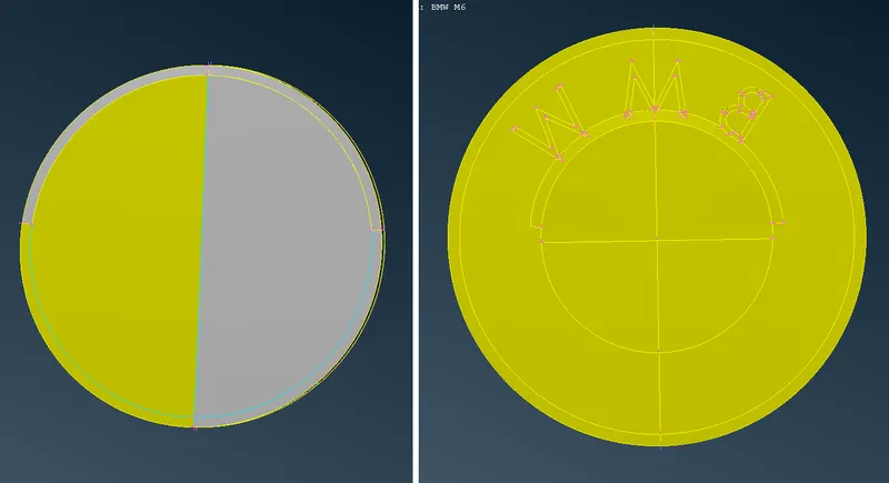
B. Cleaning Logo: -
i. Description of Tools used(Reference - ANSA Help): -
a. Not `->` Hide one or more selected entities.
b. Delete `->` The Delete function of the Geometry Group can be used to delete various ANSA entities (Curves, Faces, FE-Model entities, etc.).
c. New(Faces) `->` This function defines a new surface by selecting its boundary curves and creates a corresponding face that covers the new surface. The calculated surface appears as a net.
d. Cut(Faces) `->` This function cuts (splits) an existing Face or joins faces if an inverse operation is applied (right mouse button). It does not require the existence of Hot Points since it can be applied directly on an arbitrary position of a CONS.
e. Delete(Hot Points) `->` This function deletes Hot Points lying on a CONS segment. After deletion, the adjacent CONS segments sharing the Hot Point become one.
ii. Step OUTPUT: -

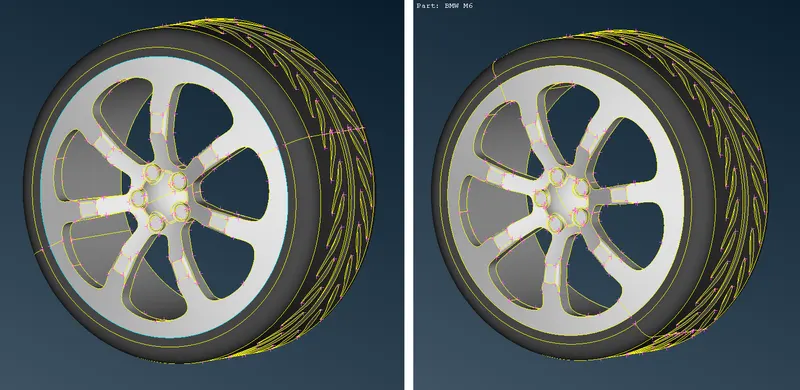
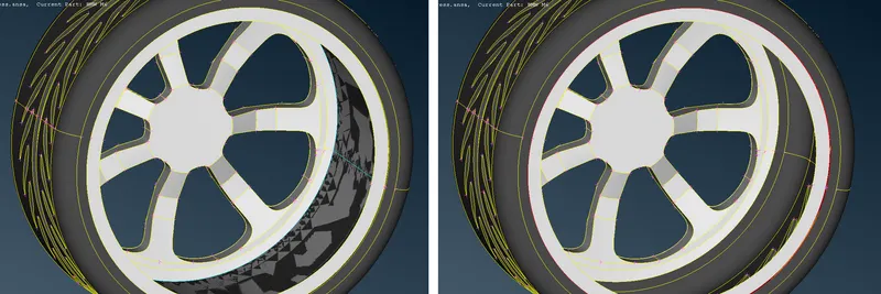
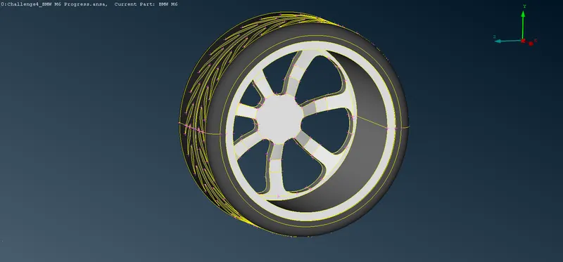
C. Cleaning Rims and Tyres: -
i. Description of Tools used(Reference - ANSA Help): -
a. Not `->` Hide one or more selected entities.
b. Delete `->` The Delete function of the Geometry Group can be used to delete various ANSA entities (Curves, Faces, FE-Model entities, etc.).
c. New(Faces) `->` This function defines a new surface by selecting its boundary curves and creates a corresponding face that covers the new surface. The calculated surface appears as a net.
d. Cut(Faces) `->` This function cuts (splits) an existing Face or joins faces if an inverse operation is applied (right mouse button). It does not require the existence of Hot Points since it can be applied directly on an arbitrary position of a CONS.
e. Delete(Hot Points) `->` This function deletes Hot Points lying on a CONS segment. After deletion, the adjacent CONS segments sharing the Hot Point become one.
ii. Step OUTPUT: -
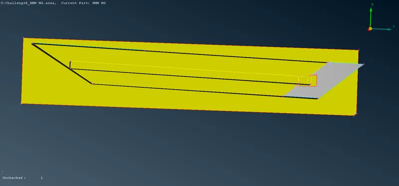
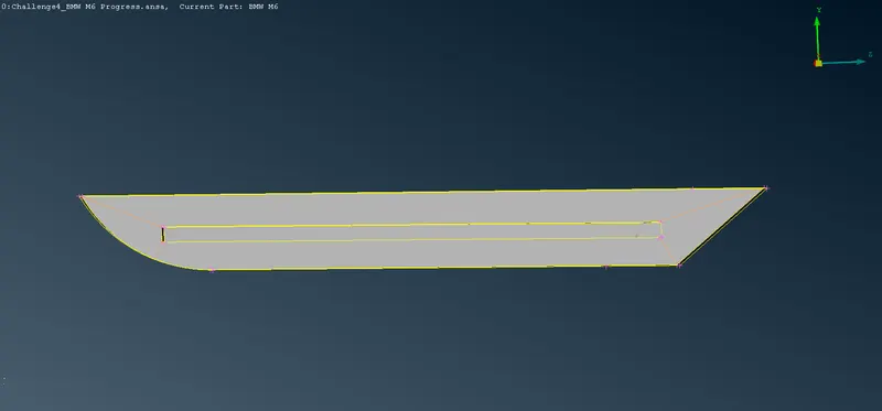
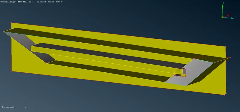
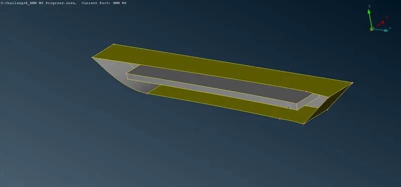
8. Performing Geometric Cleanup of Body: -
A. Cleaning Side Body: -
i. Description of Tools used(Reference - ANSA Help): -
a. Not `->` Hide one or more selected entities.
b. Delete `->` The Delete function of the Geometry Group can be used to delete various ANSA entities (Curves, Faces, FE-Model entities, etc.).
c. New(Faces) `->` This function defines a new surface by selecting its boundary curves and creates a corresponding face that covers the new surface. The calculated surface appears as a net.
d. Cut(Faces) `->` This function cuts (splits) an existing Face or joins faces if an inverse operation is applied (right mouse button). It does not require the existence of Hot Points since it can be applied directly on an arbitrary position of a CONS.
e. Topo(Faces) `->` This function automatically creates topological conditions between selected adjacent CONS.
f. Delete(Hot Points) `->` This function deletes Hot Points lying on a CONS segment. After deletion, the adjacent CONS segments sharing the Hot Point become one.
ii. Step OUTPUT: -
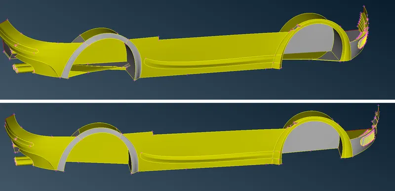
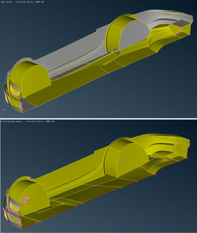
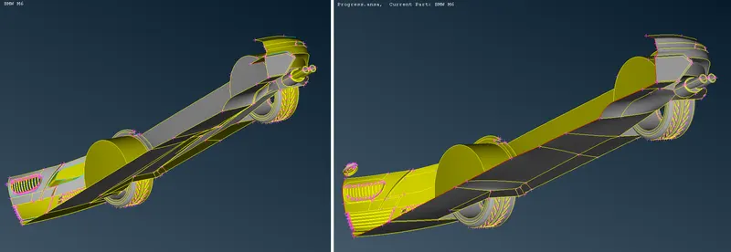
A. Cleaning Lower Body: -
i. Description of Tools used(Reference - ANSA Help): -
a. Not `->` Hide one or more selected entities.
b. Delete `->` The Delete function of the Geometry Group can be used to delete various ANSA entities (Curves, Faces, FE-Model entities, etc.).
c. New(Faces) `->` This function defines a new surface by selecting its boundary curves and creates a corresponding face that covers the new surface. The calculated surface appears as a net.
d. Cut(Faces) `->` This function cuts (splits) an existing Face or joins faces if an inverse operation is applied (right mouse button). It does not require the existence of Hot Points since it can be applied directly on an arbitrary position of a CONS.
e. Create(Curves) `->` This function streamlines legacy functionality for Planar and 3-D curves, including primitive planar shapes (circles and ellipses, rectangles), and adds corner fillet, trim, and offset capabilities. Support may be derived from geometric and element entities (e.g., Faces, CONS, Curves, Nodes, Elements, Working Planes e.t.c).
f. Topo(Faces) `->` This function automatically creates topological conditions between selected adjacent CONS.
g. Delete(Hot Points) `->` This function deletes Hot Points lying on a CONS segment. After deletion, the adjacent CONS segments sharing the Hot Point become one.
ii. Step OUTPUT: -
9. Performing Geometric Check and Creating Symmetric Surface of the Model: -
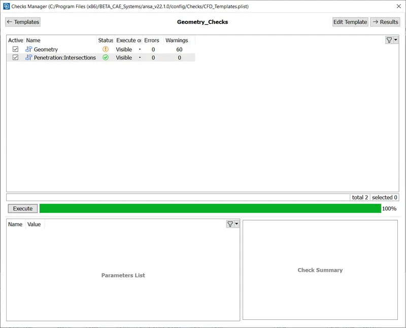
A. Performing Half Geometric Check: -
i. Description of Tools used: -
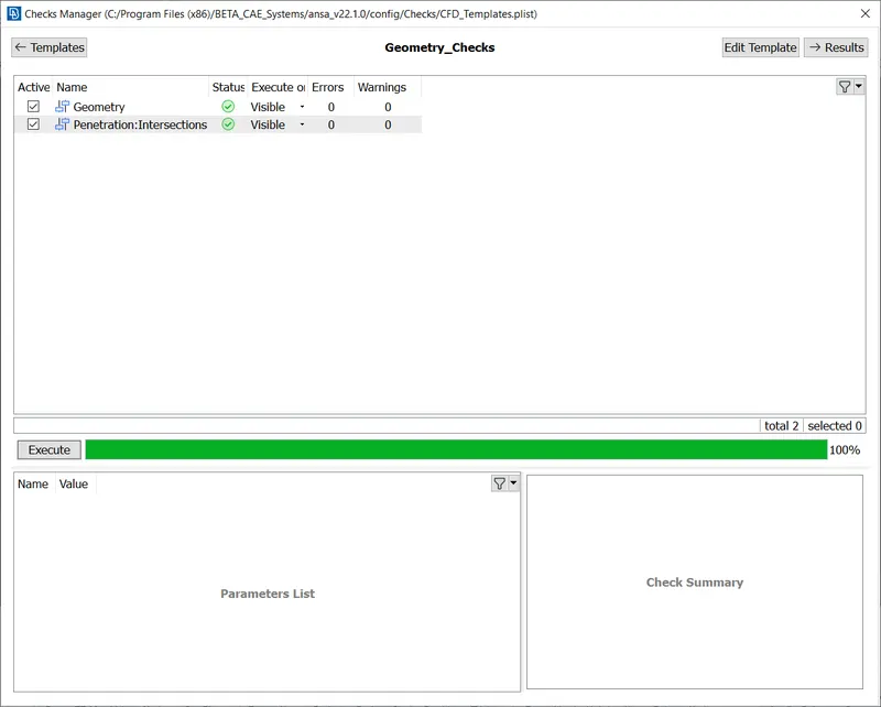
a. Check Manager(Checks) `->` This is a Tool used to Check for different types of errors. Mainly used for Geometric and Penetration Errors.
ii. Step OUTPUT: -
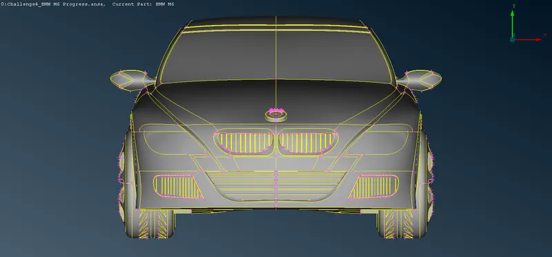
B. Generating the Complete Model by Creating Symmetric Surfaces: -
i. Description of Tools used(Reference - ANSA Help): -
a. Copy(Transform) `->` This function is used to Translate, Rotate, Transform, Scale, Symmetry or Mirror selected entities (Faces, Points, Elements etc). The selected entities are copied in the new position.
ii. Step OUTPUT: -
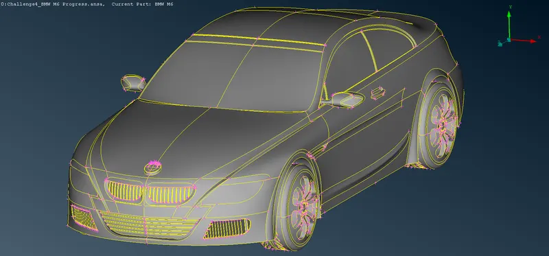
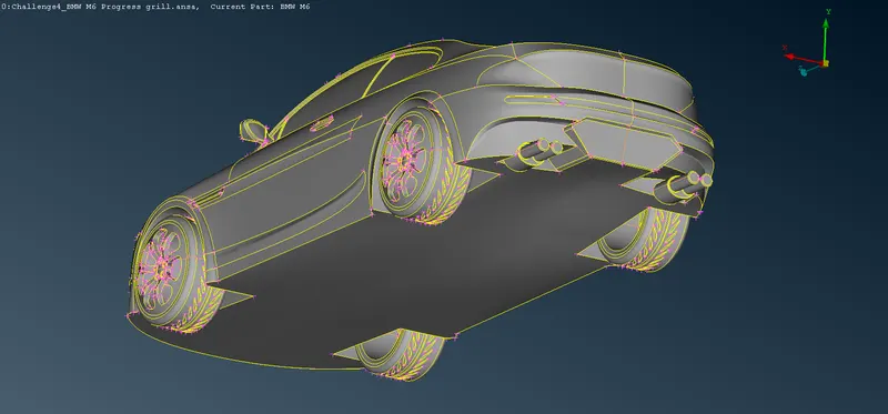
C. Performing Full Car Model Geometric Check: -
i. Description of Tools used: -
a. Check Manager(Checks) `->` This is a Tool used to Check for different types of errors. Mainly used for Geometric and Penetration Errors.
ii. Step OUTPUT: -
10. Giving PID Naming: -
A. Description of Tools used(Reference - ANSA Help): -
i. Properties `->` This function facilitates property management. A list of the properties existing in the file is available. Management windows, such as this one, provide filtering, sorting, and selection capabilities on the listed entities as well as the definition of new entities.
ii. The Components of the Model are given the Following Names: -
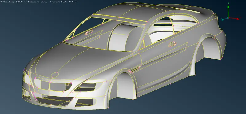
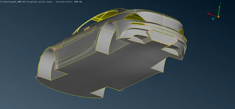
a. Body: -
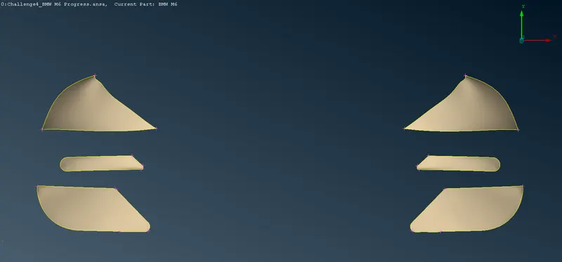
b. Lights: -
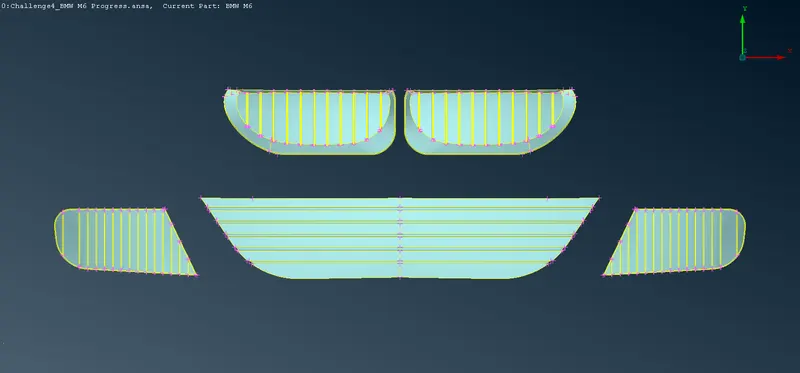
c. Grills: -
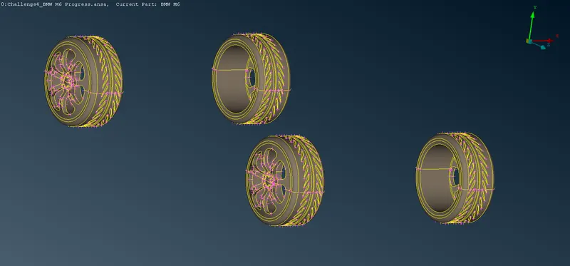
d. Rims and Tyres: -
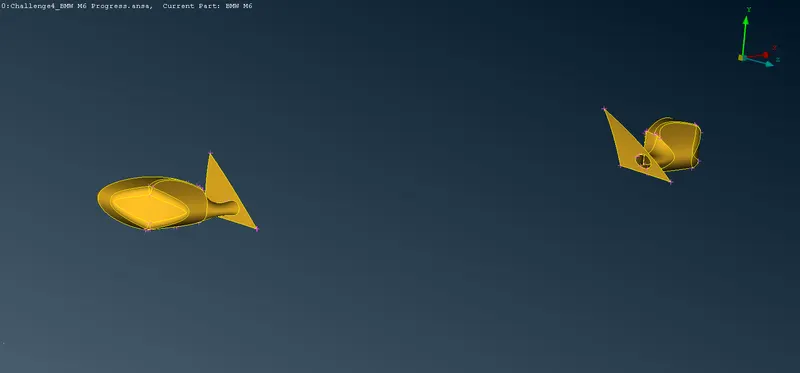
e. Optical Rear View Mirror: -
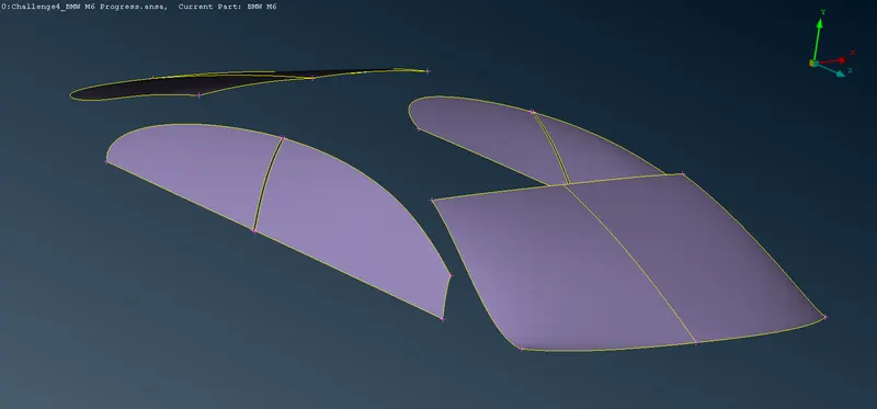
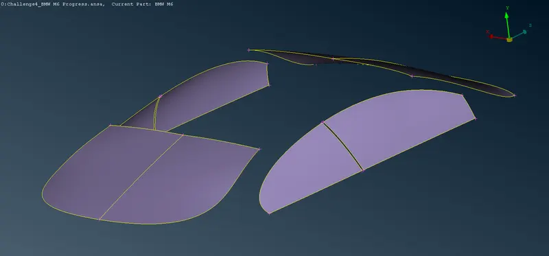
f. Window: -
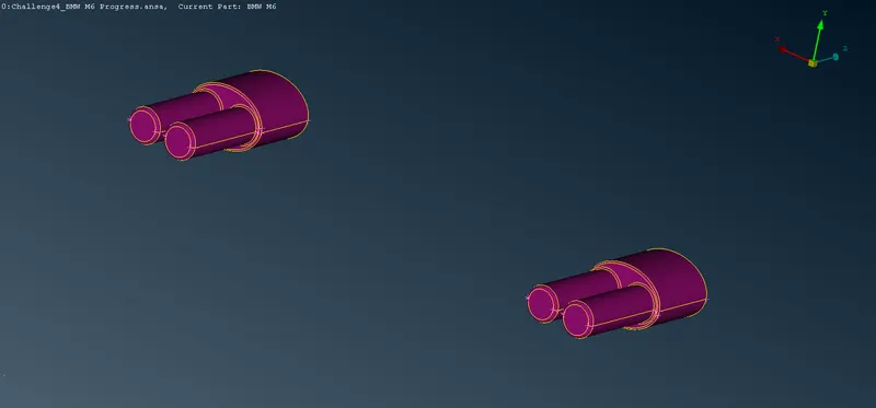
g. Silencer: -
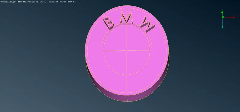
h. Logo: -
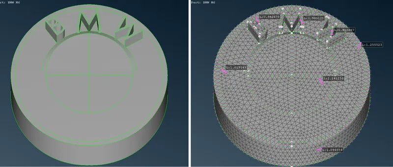
11. Performing Surface Mesh: -
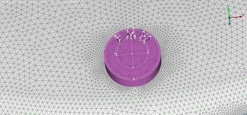
A. 1mm Surface Mesh on Logo: -
i. Description of Tools used: -
a. Mesh Parameters `->` This function opens the 'Mesh Parameters' window, where the user can define the parameters for the Reconstruction, Reshape and Fix functions.
b. Quality criteria `->` Select and set the respective quality criteria for the corresponding elements to perform the Quality Checks (Hidden Mode). Also, set the general presentation settings concerning the ANSA workspace.
c. Length(Perimeters) `->` This function defines the element length on selected perimeter segments or macro areas. The element length may be explicitly declared or may be declared as a factor to be multiplied by the existing element length.
d. CFD(Mesh Generation) `->` This function is recommended after the user has applied the Perimeters>Spacing(Auto CFD) on the selected perimeters. This algorithm meshes with variable element length, depending on the local curvature of the underlying CAD surface, under tight user-controlled specifications. It generated the less possible elements taking into account all small details of the geometry. This algorithm is an advanced meshing algorithm tailor-made to meet CFD specs or other application areas where a variable-size mesh is required.
e. Improve(Shell Mesh) `->` The function is applied on either meshed Macro Areas or FE models in order to improve the existing mesh. The user can select one of the embedded algorithms: Reconstruct, Reshape, Smooth, or Fix Quality.
f. Split(Elements) `->` This function splits quadrilateral and triangular shell elements into smaller ones. Element splitting is performed between selected nodes and/or inserted nodes along selected element edges. The function can be applied on individual or groups of shell elements in order to improve the mesh orientation, reduce the number of triangles, or refine locally or globally the mesh of a part. Refer to ANSA User's Guide for a detailed description of the use of the function.
ii. Step OUTPUT: -
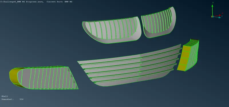
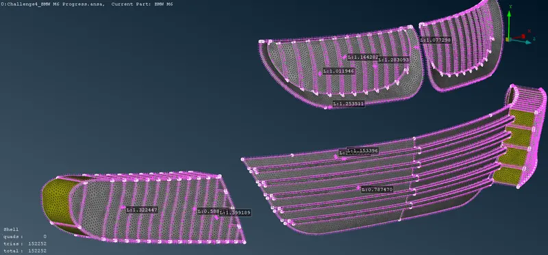
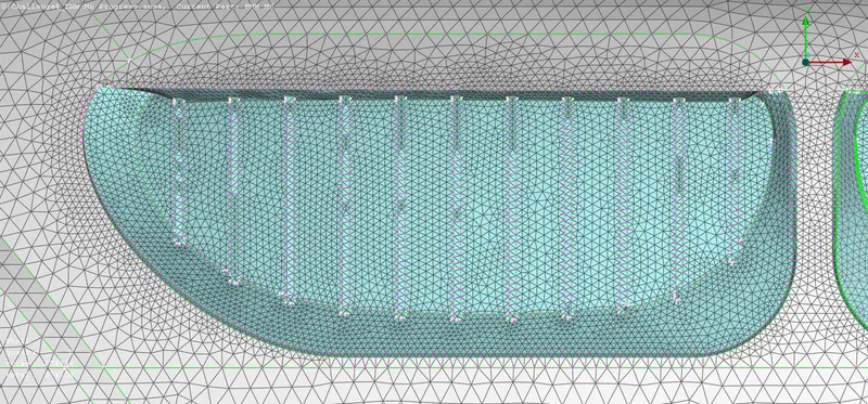
B. 1mm Surface Mesh on Grills: -
i. Description of Tools used: -
a. Mesh Parameters `->` This function opens the 'Mesh Parameters' window, where the user can define the parameters for the Reconstruction, Reshape and Fix functions.
b. Quality criteria `->` Select and set the respective quality criteria for the corresponding elements to perform the Quality Checks (Hidden Mode). Also, set the general presentation settings concerning the ANSA workspace.
c. Length(Perimeters) `->` This function defines the element length on selected perimeter segments or macro areas. The element length may be explicitly declared or may be declared as a factor to be multiplied by the existing element length.
d. CFD(Mesh Generation) `->` This function is recommended after the user has applied the Perimeters>Spacing(Auto CFD) on the selected perimeters. This algorithm meshes with variable element length, depending on the local curvature of the underlying CAD surface, under tight user-controlled specifications. It generated the less possible elements taking into account all small details of the geometry. This algorithm is an advanced meshing algorithm tailor-made to meet CFD specs or other application areas where a variable-size mesh is required.
e. Improve(Shell Mesh) `->` The function is applied on either meshed Macro Areas or FE models in order to improve the existing mesh. The user can select one of the embedded algorithms: Reconstruct, Reshape, Smooth, or Fix Quality.
f. Split(Elements) `->` This function splits quadrilateral and triangular shell elements into smaller ones. Element splitting is performed between selected nodes and/or inserted nodes along selected element edges. The function can be applied on individual or groups of shell elements in order to improve the mesh orientation, reduce the number of triangles, or refine locally or globally the mesh of a part. Refer to ANSA User's Guide for a detailed description of the use of the function.
ii. Step OUTPUT: -
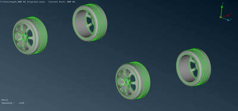
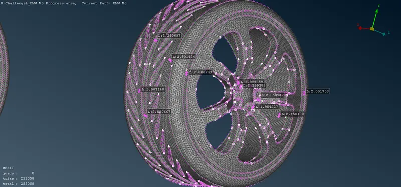
C. 2mm Surface Mesh on Rims and Types: -
i. Description of Tools used: -
a. Mesh Parameters `->` This function opens the 'Mesh Parameters' window, where the user can define the parameters for the Reconstruction, Reshape and Fix functions.
b. Quality criteria `->` Select and set the respective quality criteria for the corresponding elements to perform the Quality Checks (Hidden Mode). Also, set the general presentation settings concerning the ANSA workspace.
c. Length(Perimeters) `->` This function defines the element length on selected perimeter segments or macro areas. The element length may be explicitly declared or may be declared as a factor to be multiplied by the existing element length.
d. CFD(Mesh Generation) `->` This function is recommended after the user has applied the Perimeters>Spacing(Auto CFD) on the selected perimeters. This algorithm meshes with variable element length, depending on the local curvature of the underlying CAD surface, under tight user-controlled specifications. It generated the less possible elements taking into account all small details of the geometry. This algorithm is an advanced meshing algorithm tailor-made to meet CFD specs or other application areas where a variable-size mesh is required.
e. Improve(Shell Mesh) `->` The function is applied on either meshed Macro Areas or FE models in order to improve the existing mesh. The user can select one of the embedded algorithms: Reconstruct, Reshape, Smooth, or Fix Quality.
f. Split(Elements) `->` This function splits quadrilateral and triangular shell elements into smaller ones. Element splitting is performed between selected nodes and/or inserted nodes along selected element edges. The function can be applied on individual or groups of shell elements in order to improve the mesh orientation, reduce the number of triangles, or refine locally or globally the mesh of a part. Refer to ANSA User's Guide for a detailed description of the use of the function.
ii. Step OUTPUT: -
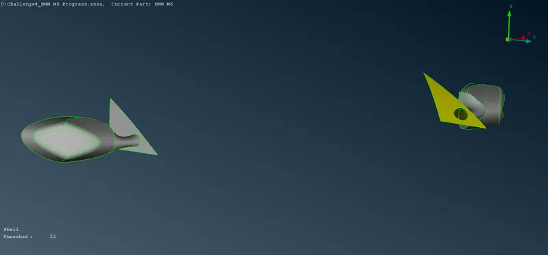
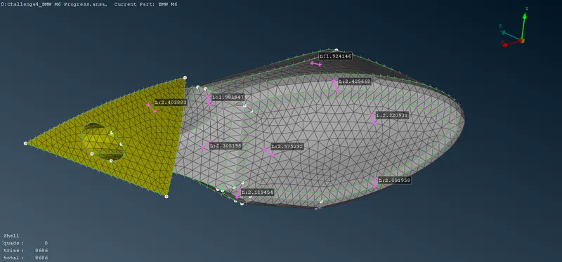
D. 2mm Surface Mesh on Optical Rear view mirror: -
i. Description of Tools used: -
a. Mesh Parameters `->` This function opens the 'Mesh Parameters' window, where the user can define the parameters for the Reconstruction, Reshape and Fix functions.
b. Quality criteria `->` Select and set the respective quality criteria for the corresponding elements to perform the Quality Checks (Hidden Mode). Also, set the general presentation settings concerning the ANSA workspace.
c. Length(Perimeters) `->` This function defines the element length on selected perimeter segments or macro areas. The element length may be explicitly declared or may be declared as a factor to be multiplied by the existing element length.
d. CFD(Mesh Generation) `->` This function is recommended after the user has applied the Perimeters>Spacing(Auto CFD) on the selected perimeters. This algorithm meshes with variable element length, depending on the local curvature of the underlying CAD surface, under tight user-controlled specifications. It generated the less possible elements taking into account all small details of the geometry. This algorithm is an advanced meshing algorithm tailor-made to meet CFD specs or other application areas where a variable-size mesh is required.
e. Improve(Shell Mesh) `->` The function is applied on either meshed Macro Areas or FE models in order to improve the existing mesh. The user can select one of the embedded algorithms: Reconstruct, Reshape, Smooth, or Fix Quality.
f. Split(Elements) `->` This function splits quadrilateral and triangular shell elements into smaller ones. Element splitting is performed between selected nodes and/or inserted nodes along selected element edges. The function can be applied on individual or groups of shell elements in order to improve the mesh orientation, reduce the number of triangles, or refine locally or globally the mesh of a part. Refer to ANSA User's Guide for a detailed description of the use of the function.
ii. Step OUTPUT: -
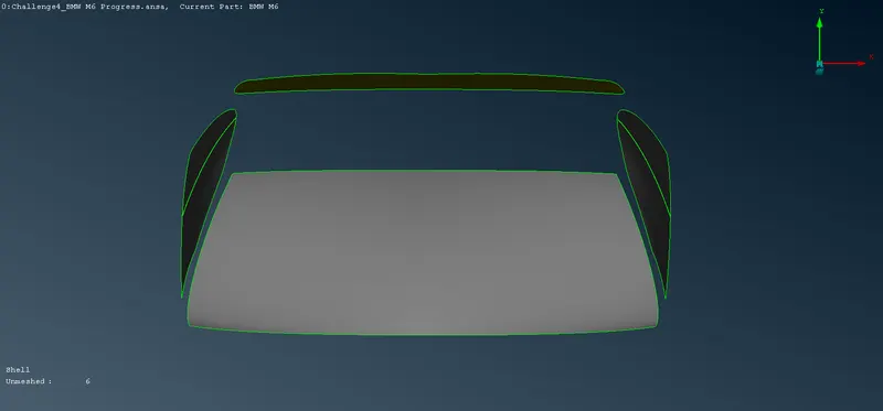
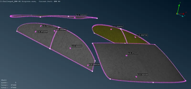
E. 2mm Surface Mesh on Windows: -
i. Description of Tools used: -
a. Mesh Parameters `->` This function opens the 'Mesh Parameters' window, where the user can define the parameters for the Reconstruction, Reshape and Fix functions.
b. Quality criteria `->` Select and set the respective quality criteria for the corresponding elements to perform the Quality Checks (Hidden Mode). Also, set the general presentation settings concerning the ANSA workspace.
c. Length(Perimeters) `->` This function defines the element length on selected perimeter segments or macro areas. The element length may be explicitly declared or may be declared as a factor to be multiplied by the existing element length.
d. CFD(Mesh Generation) `->` This function is recommended after the user has applied the Perimeters>Spacing(Auto CFD) on the selected perimeters. This algorithm meshes with variable element length, depending on the local curvature of the underlying CAD surface, under tight user-controlled specifications. It generated the less possible elements taking into account all small details of the geometry. This algorithm is an advanced meshing algorithm tailor-made to meet CFD specs or other application areas where a variable-size mesh is required.
e. Improve(Shell Mesh) `->` The function is applied on either meshed Macro Areas or FE models in order to improve the existing mesh. The user can select one of the embedded algorithms: Reconstruct, Reshape, Smooth, or Fix Quality.
f. Split(Elements) `->` This function splits quadrilateral and triangular shell elements into smaller ones. Element splitting is performed between selected nodes and/or inserted nodes along selected element edges. The function can be applied on individual or groups of shell elements in order to improve the mesh orientation, reduce the number of triangles, or refine locally or globally the mesh of a part. Refer to ANSA User's Guide for a detailed description of the use of the function.
ii. Step OUTPUT: -
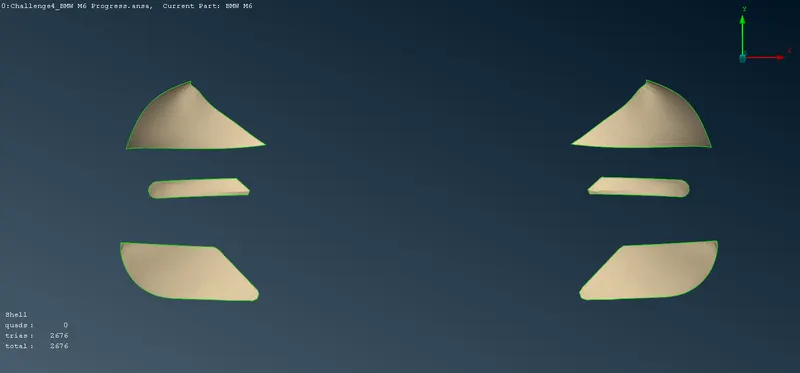
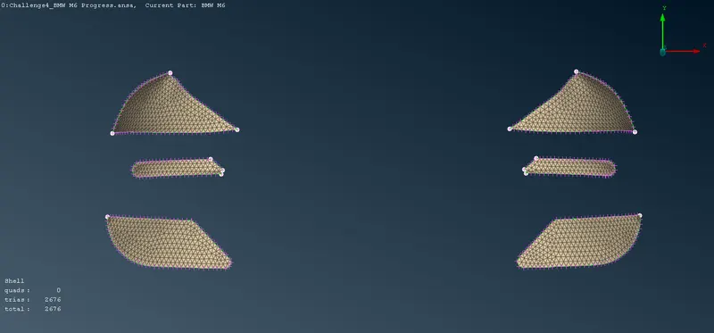
F. 4mm Surface Mesh on Lights: -
i. Description of Tools used: -
a. Mesh Parameters `->` This function opens the 'Mesh Parameters' window, where the user can define the parameters for the Reconstruction, Reshape and Fix functions.
b. Quality criteria `->` Select and set the respective quality criteria for the corresponding elements to perform the Quality Checks (Hidden Mode). Also, set the general presentation settings concerning the ANSA workspace.
c. Length(Perimeters) `->` This function defines the element length on selected perimeter segments or macro areas. The element length may be explicitly declared or may be declared as a factor to be multiplied by the existing element length.
d. CFD(Mesh Generation) `->` This function is recommended after the user has applied the Perimeters>Spacing(Auto CFD) on the selected perimeters. This algorithm meshes with variable element length, depending on the local curvature of the underlying CAD surface, under tight user-controlled specifications. It generated the less possible elements taking into account all small details of the geometry. This algorithm is an advanced meshing algorithm tailor-made to meet CFD specs or other application areas where a variable-size mesh is required.
e. Improve(Shell Mesh) `->` The function is applied on either meshed Macro Areas or FE models in order to improve the existing mesh. The user can select one of the embedded algorithms: Reconstruct, Reshape, Smooth, or Fix Quality.
f. Split(Elements) `->` This function splits quadrilateral and triangular shell elements into smaller ones. Element splitting is performed between selected nodes and/or inserted nodes along selected element edges. The function can be applied on individual or groups of shell elements in order to improve the mesh orientation, reduce the number of triangles, or refine locally or globally the mesh of a part. Refer to ANSA User's Guide for a detailed description of the use of the function.
ii. Step OUTPUT: -
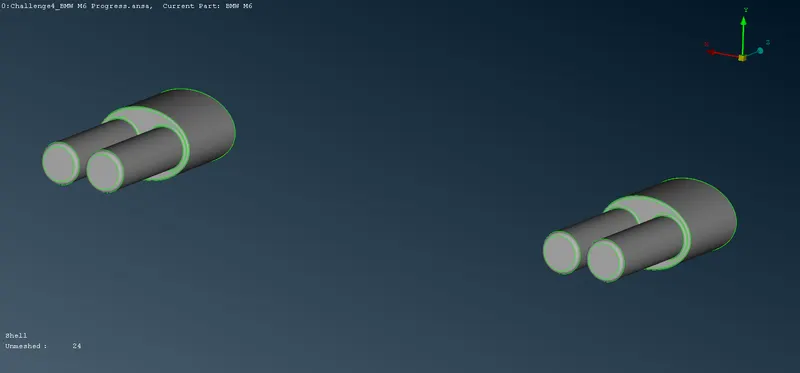
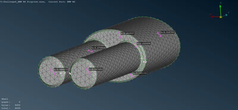
G. 3mm Surface Mesh on Silencers: -
i. Description of Tools used: -
a. Mesh Parameters `->` This function opens the 'Mesh Parameters' window, where the user can define the parameters for the Reconstruction, Reshape and Fix functions.
b. Quality criteria `->` Select and set the respective quality criteria for the corresponding elements to perform the Quality Checks (Hidden Mode). Also, set the general presentation settings concerning the ANSA workspace.
c. Length(Perimeters) `->` This function defines the element length on selected perimeter segments or macro areas. The element length may be explicitly declared or may be declared as a factor to be multiplied by the existing element length.
d. CFD(Mesh Generation) `->` This function is recommended after the user has applied the Perimeters>Spacing(Auto CFD) on the selected perimeters. This algorithm meshes with variable element length, depending on the local curvature of the underlying CAD surface, under tight user-controlled specifications. It generated the less possible elements taking into account all small details of the geometry. This algorithm is an advanced meshing algorithm tailor-made to meet CFD specs or other application areas where a variable-size mesh is required.
e. Improve(Shell Mesh) `->` The function is applied on either meshed Macro Areas or FE models in order to improve the existing mesh. The user can select one of the embedded algorithms: Reconstruct, Reshape, Smooth, or Fix Quality.
f. Split(Elements) `->` This function splits quadrilateral and triangular shell elements into smaller ones. Element splitting is performed between selected nodes and/or inserted nodes along selected element edges. The function can be applied on individual or groups of shell elements in order to improve the mesh orientation, reduce the number of triangles, or refine locally or globally the mesh of a part. Refer to ANSA User's Guide for a detailed description of the use of the function.
ii. Step OUTPUT: -
H. 3mm Surface Mesh on Body: -
i. Description of Tools used: -
a. Mesh Parameters `->` This function opens the 'Mesh Parameters' window, where the user can define the parameters for the Reconstruction, Reshape and Fix functions.
b. Quality criteria `->` Select and set the respective quality criteria for the corresponding elements to perform the Quality Checks (Hidden Mode). Also, set the general presentation settings concerning the ANSA workspace.
c. Length(Perimeters) `->` This function defines the element length on selected perimeter segments or macro areas. The element length may be explicitly declared or may be declared as a factor to be multiplied by the existing element length.
d. CFD(Mesh Generation) `->` This function is recommended after the user has applied the Perimeters>Spacing(Auto CFD) on the selected perimeters. This algorithm meshes with variable element length, depending on the local curvature of the underlying CAD surface, under tight user-controlled specifications. It generated the less possible elements taking into account all small details of the geometry. This algorithm is an advanced meshing algorithm tailor-made to meet CFD specs or other application areas where a variable-size mesh is required.
e. Improve(Shell Mesh) `->` The function is applied on either meshed Macro Areas or FE models in order to improve the existing mesh. The user can select one of the embedded algorithms: Reconstruct, Reshape, Smooth, or Fix Quality.
f. Split(Elements) `->` This function splits quadrilateral and triangular shell elements into smaller ones. Element splitting is performed between selected nodes and/or inserted nodes along selected element edges. The function can be applied on individual or groups of shell elements in order to improve the mesh orientation, reduce the number of triangles, or refine locally or globally the mesh of a part. Refer to ANSA User's Guide for a detailed description of the use of the function.
ii. Step OUTPUT: -
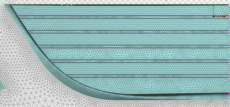
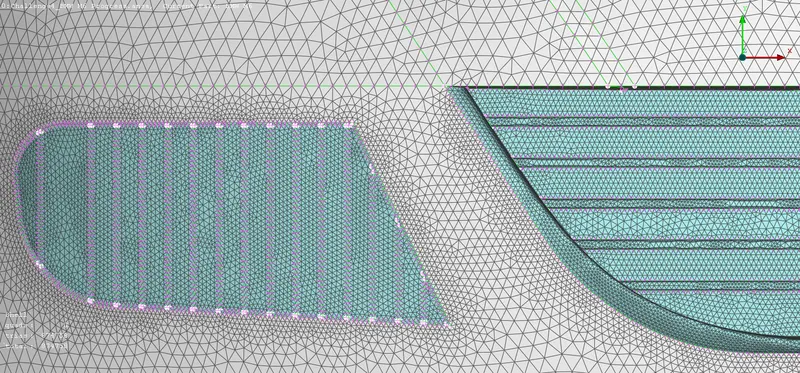
12. Developing and Meshing Wind Tunnel: -
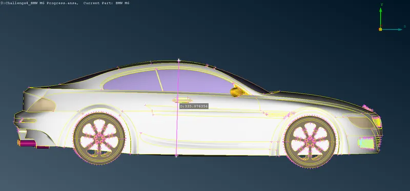
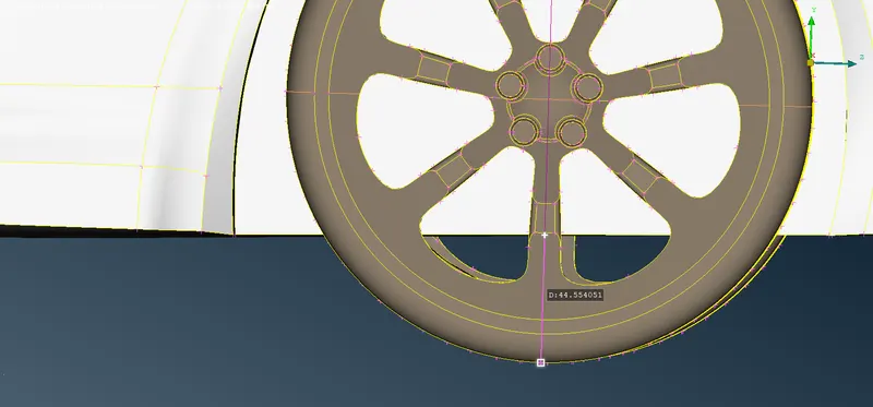
A. Measuring Car Dimensions: -
i. Description of Tools used: -
a. Measure `->` This function performs various measurements according to the corresponding Selection Mode. The applied measurements can be saved and viewed at a later stage.
b. Relative(Points) `->` This function defines new 3D points that lie on a given relative position from a number of selected 3D points, Hot Points, Weld Points, etc. The input of a (dx, dy, dz) vector or an indication by the mouse is required for the definition of the relative position.
c. Create(curves) `->` This function streamlines legacy functionality for Planar and 3-D curves, including primitive planar shapes (circles and ellipses, rectangles), and adds corner fillet, trim, and offset capabilities. Support may be derived from geometric and element entities (e.g., Faces, CONS, Curves, Nodes, Elements, Working Planes e.t.c).
ii. Step OUTPUT: -
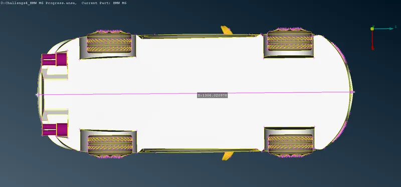
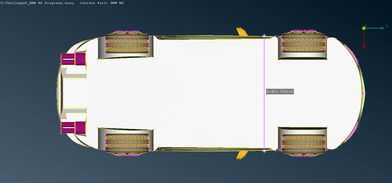
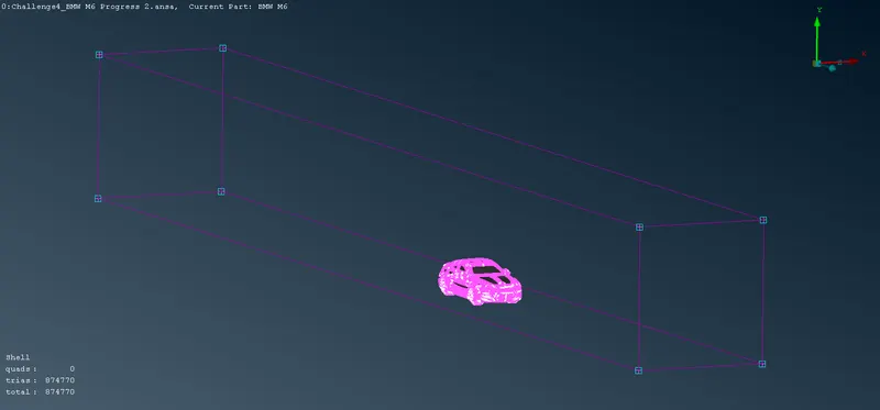
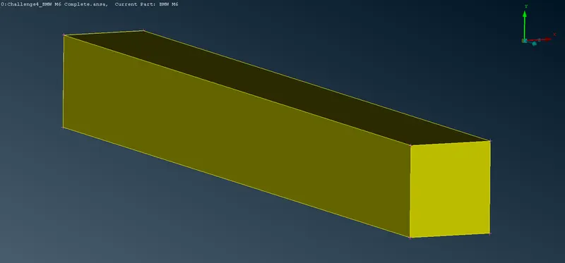
B. Making Wind Tunnel: -
i. Description of Tools used: -
a. Relative(Points) `->` This function defines new 3D points that lie on a given relative position from a number of selected 3D points, Hot Points, Weld Points, etc. The input of a (dx, dy, dz) vector or an indication by the mouse is required for the definition of the relative position.
b. Create(curves) `->` This function streamlines legacy functionality for Planar and 3-D curves, including primitive planar shapes (circles and ellipses, rectangles), and adds corner fillet, trim, and offset capabilities. Support may be derived from geometric and element entities (e.g., Faces, CONS, Curves, Nodes, Elements, Working Planes e.t.c).
c. New(Faces) `->` This function defines a new surface by selecting its boundary curves and creates a corresponding face that covers the new surface. The calculated surface appears as a net.
ii. Step OUTPUT: -
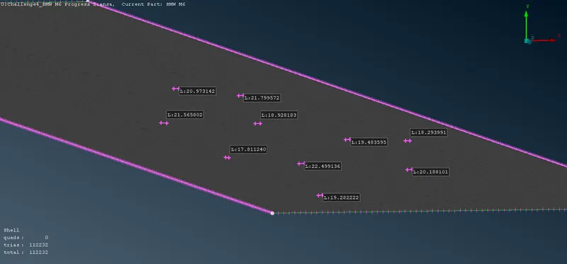
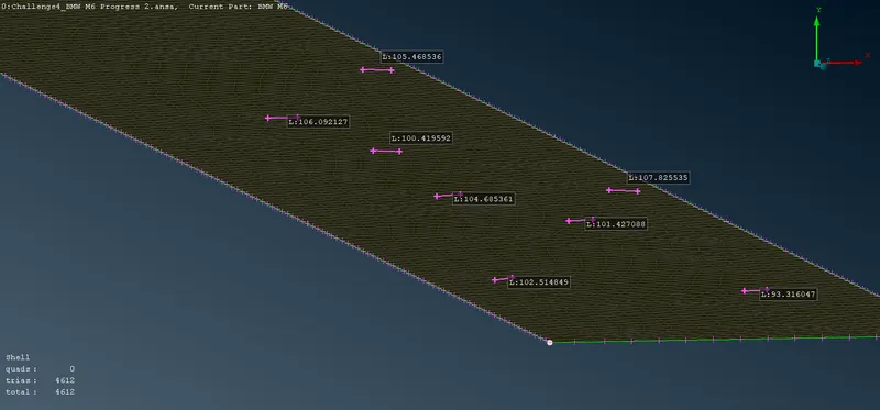
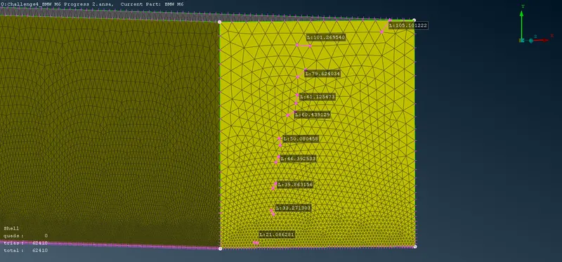
C. Meshing Wind Tunnel: -
i. Description of Tools used: -
a. Mesh Parameters `->` This function opens the 'Mesh Parameters' window, where the user can define the parameters for the Reconstruction, Reshape and Fix functions.
b. Quality criteria `->` Select and set the respective quality criteria for the corresponding elements to perform the Quality Checks (Hidden Mode). Also, set the general presentation settings concerning the ANSA workspace.
c. Length(Perimeters) `->` This function defines the element length on selected perimeter segments or macro areas. The element length may be explicitly declared or may be declared as a factor to be multiplied by the existing element length.
d. Spacing(Perimeters) `->` Manual control of nodal spacing and distribution on perimeter segment. There are five available node-biasing modes in ANSA, Linear, Geometric, Bi-Geometric, Bell Curve, and User Defined. This function can be applied only on CONS, if there is no CONS in the model, the function is not activated.
e. Freeze/Un(Macros) `->` This function locks/unlocks the selected Macro Areas and their boundary segments. In this way, the Macro Areas' condition is stabilized and no participation to functions that might alter their topology or meshing (if any) is permitted. If any function tries to alter the Macro Area, or a Macro Area's component is selected to participate to another function, a relative message appears in the text window.
f. CFD(Mesh Generation) `->` This function is recommended after the user has applied the Perimeters>Spacing(Auto CFD) on the selected perimeters. This algorithm meshes with variable element length, depending on the local curvature of the underlying CAD surface, under tight user-controlled specifications. It generated the less possible elements taking into account all small details of the geometry. This algorithm is an advanced meshing algorithm tailor-made to meet CFD specs or other application areas where a variable-size mesh is required.
g. Improve(Shell Mesh) `->` The function is applied on either meshed Macro Areas or FE models in order to improve the existing mesh. The user can select one of the embedded algorithms: Reconstruct, Reshape, Smooth, or Fix Quality.
ii. Step OUTPUT: -
Click Here To Download The Completed BMW M6 Model with Wind Tunnel