Week 3 Challenge
1. Create a terrain model by different methods –
- From file
- By ASCII
- By Graphical Filter
- By text interpolation
- By elements
Aim: To Create a Terrain model by different methods
Introduction:
Digital Terrain Models (DTM) sometimes called Digital Elevation Models (DEM) is a topographic model of the bare Earth that can be manipulated by computer programs. The data files contain the elevation data of the terrain in a digital format which relates to a rectangular grid. Vegetation, buildings, and other cultural features are removed digitally - leaving just the underlying terrain.DTMs are used especially in civil engineering, geodesy & surveying, geophysics, geography, and remote sensing.
In OpenRoads, a Terrain Model is created to represent the existing surface. If the source MX Triangulation is not a continuous surface and voids exist between groups of associated triangles, then importing the triangles will yield an inaccurate Terrain model. Therefore, the Terrain must be generated from the original surveyed strings that reside in the MX TOPO model.
Procedure:
From File
Step 1: Opening File
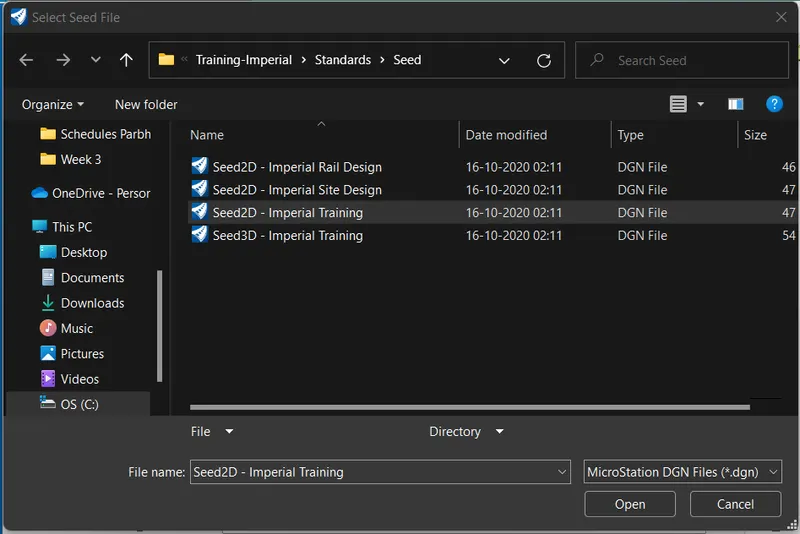
Open a New file with a 2D seed file
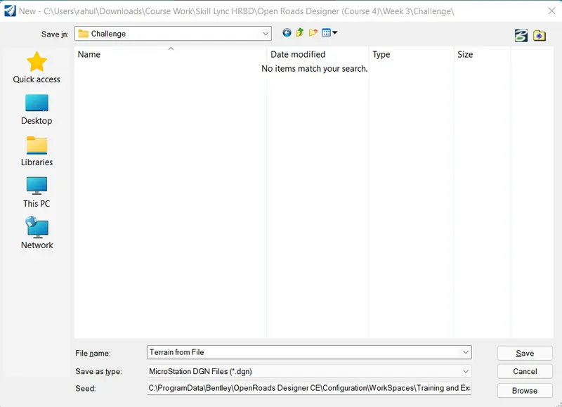
Set name as Terrain from file
Step 2: Importing Survey data
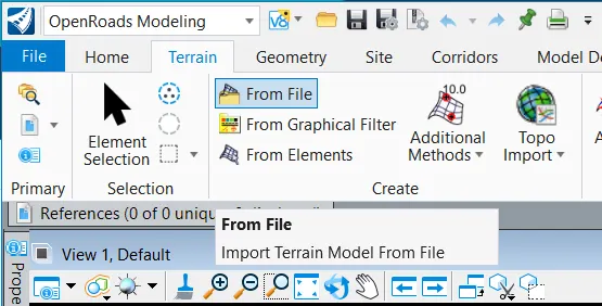
Go to the Terrain tab and click on Import From File
- Select Survey.dtm file
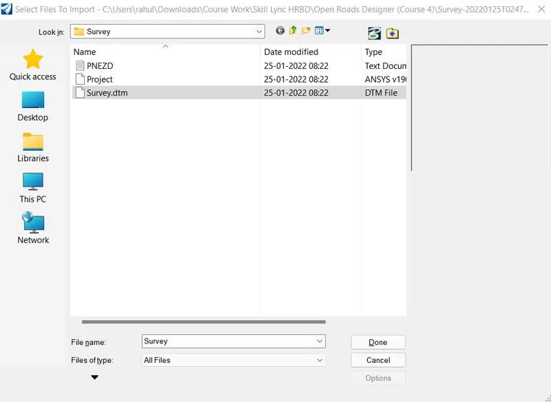
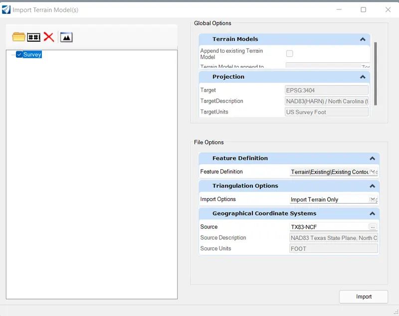
From the popup set the following settings
- Set Feature definition as Existing Contours
- Set Triangulation options as Import Terrain Only
- Set Source as following
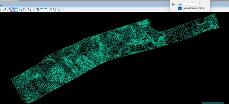
- Click on import and file is imported as follows
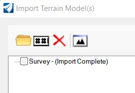
- Close the import popup
- Click on fit view to view the import data
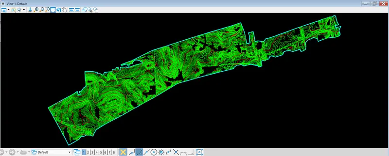
By ASCII File
Step 1: Opening File
Open a New file with 3D seed file
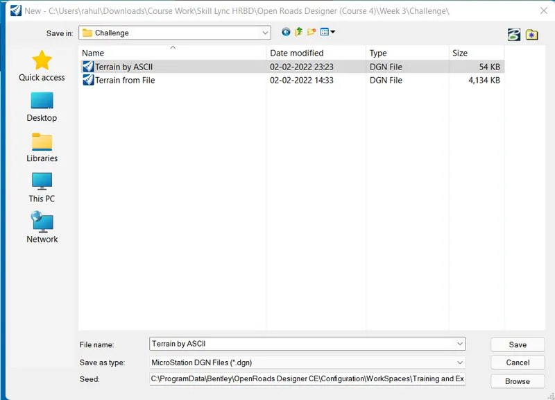
Set name as Terrain by ASCII File and click on Save
Step 2: Importing ASCII File
Go to the Terrain tab and click on Terrain by Additional Method
In that click Create Terrain model from ASCII File
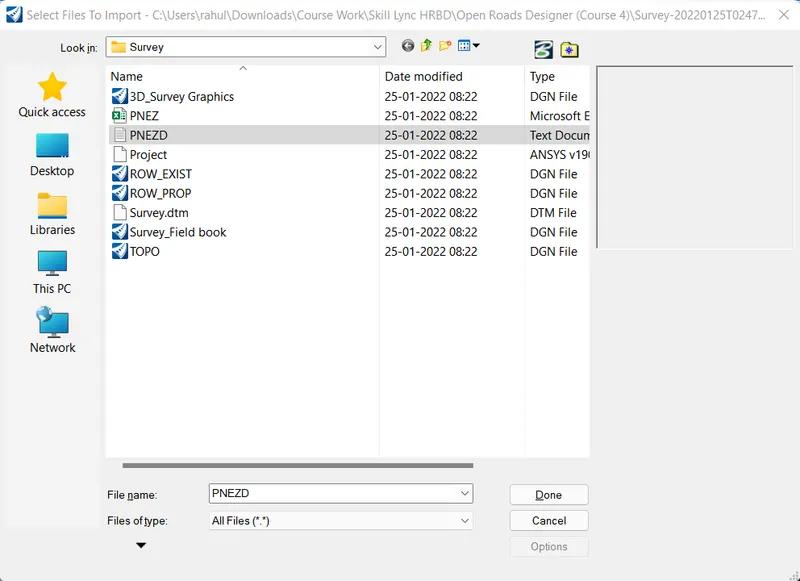
- Select PNEZD Text document
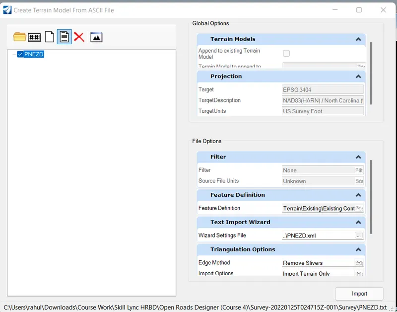
From the popup Click the Edit currently selected text import file
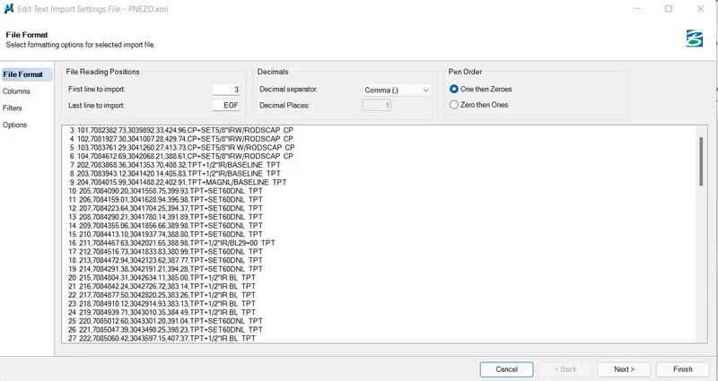
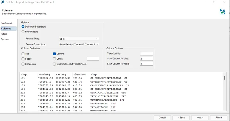
- In File Format set first line to import as '3' and Decimal seperator as 'comma'
- In Columns set feature as spot and Feature symbology
- Set Coulmn Delimiters as Comma
- Change the skip accordingly for northing, easting and elevation as follows
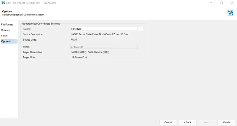
In Options tab set Source location and click finish
Save the file as LandXML for future purpose
From the popup set the following settings
- Set Feature definition as Exisiting Contours
- Set Triangulation options Edge method as 'Remove Sliver and Import options as 'Import Terrain Only' as following
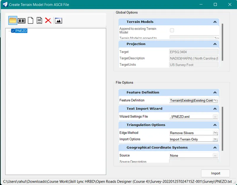
- Click on import and file is imported as follows
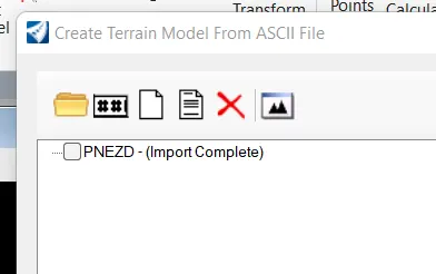
- Close the import popup
- Click on fit view to view the import data
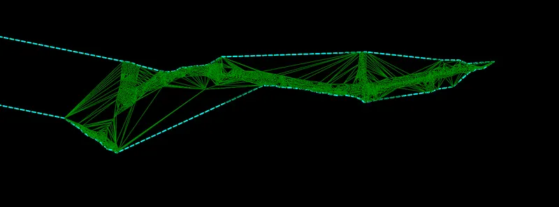
By Graphical Filter
Step 1: Opening File
Open a New file with a 3D seed file
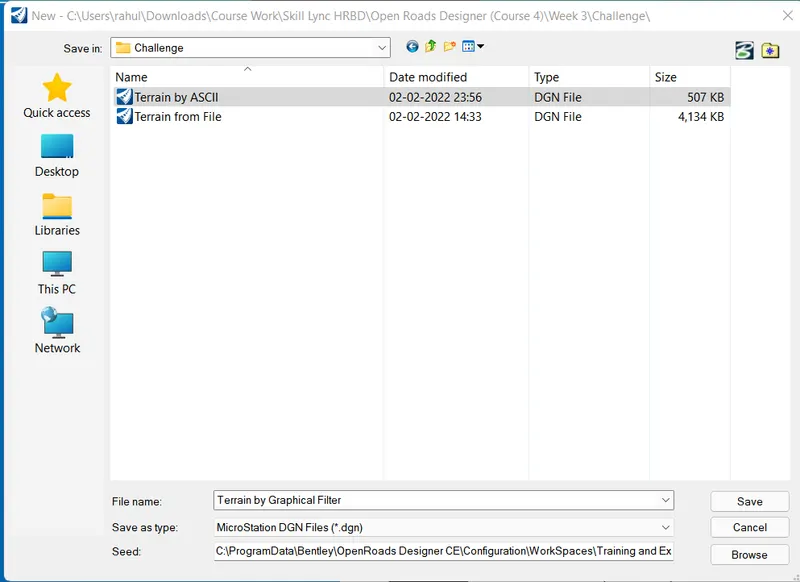
Set name as Terrain by Graphical filter and click save to open file
Step 2: Attaching Survey data
In-Home tab click on Attach tools and click on references
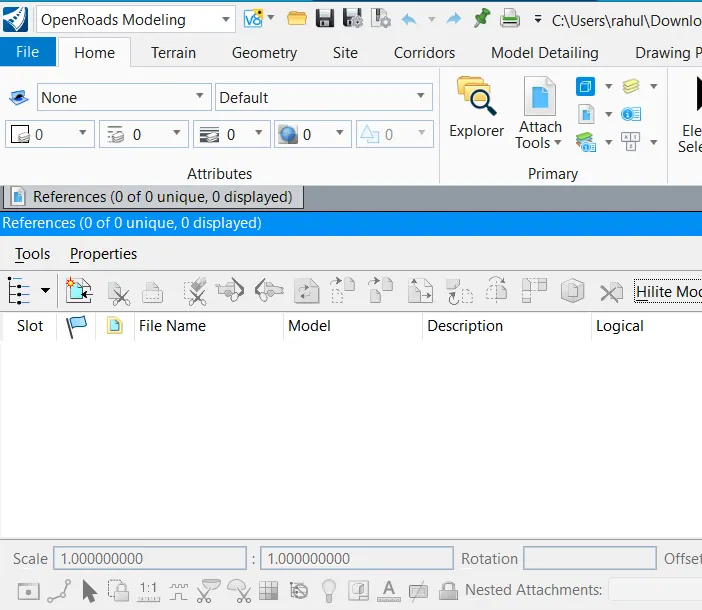
Click on Attach and select '3D_Survey Graphics file
Set attachment method as interactive
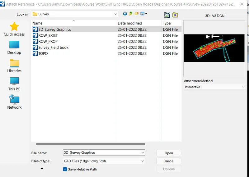
Click open and set the details as follows
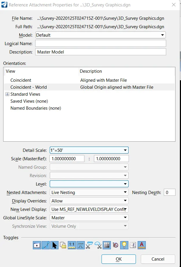
Click ok and click fit view to view the file
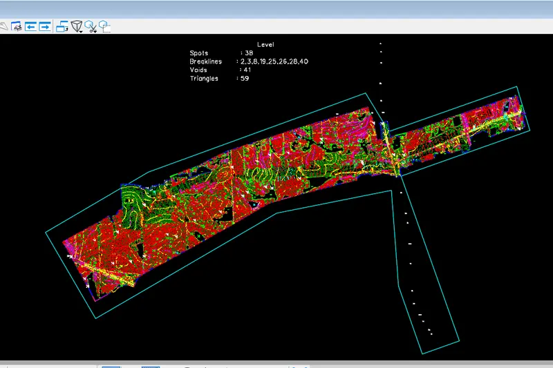
Step 3: Using Graphical Filter
Go to the Terrain tab and click on From graphical filter
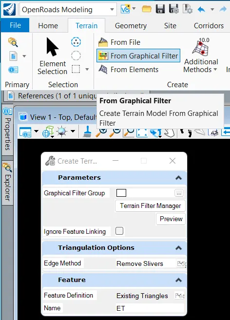
- Click on Terrain Filter manager
- Add New filter groups and filters as follows
- Name filters as Spots and brake lines
- Set Feature according and add levels of spots and Levels accordingly as follows
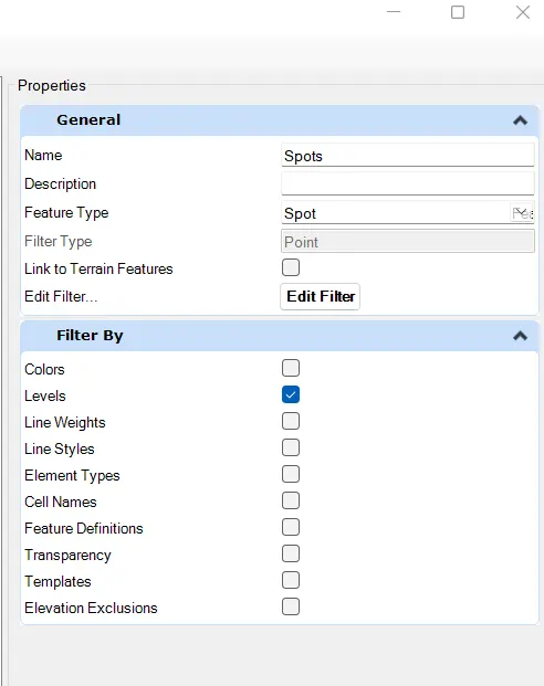
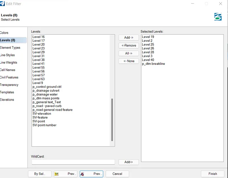
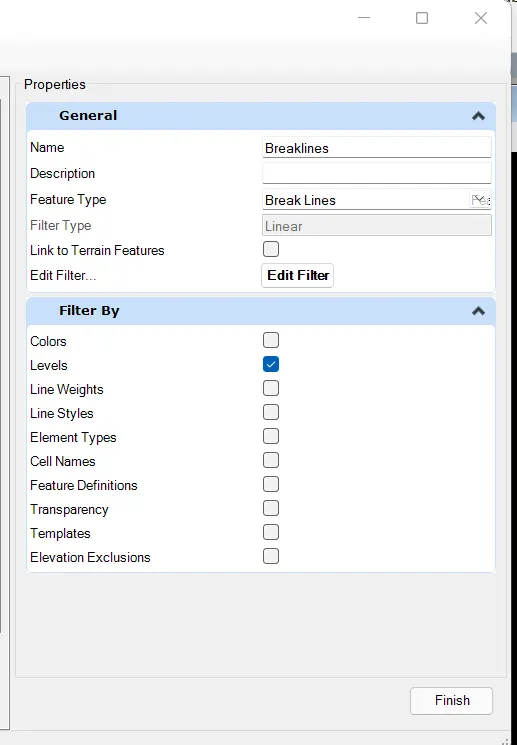
- Click finish
- Add spots filter to the terrain filter group
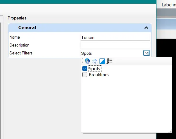
- Click finish
go to Graphical filter
- Select the filter group created
- Set Edge method as 'Remove Slivers"
- Set Feature Definition as Existing triangles
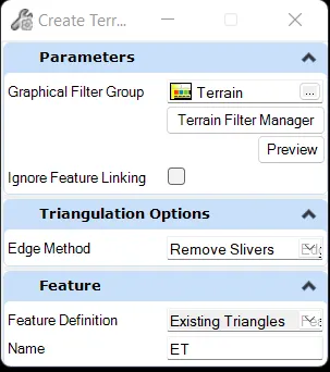
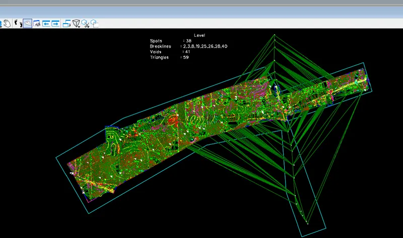
By Text interpolation
Step 1: Opening File
Open a New file with a 3D seed file
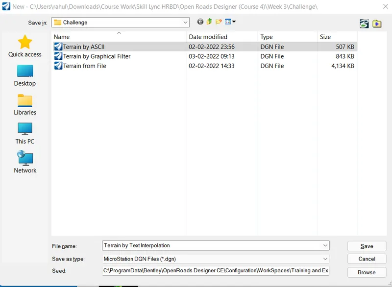
Set name as Terrain by text interpolation and click save to open file
Step 2: Attaching Survey data
In-Home tab click on Attach tools and click on references
Click on Attach and select '3D_Survey Graphics file
Set attachment method as interactive
Click open and set the details as follows
Click ok and click fit view to view the file
Step 3: Creating terrain
Go to the Terrain tab and click on Terrain by Additional Method
In that click Create Terrain model by Text interpolation
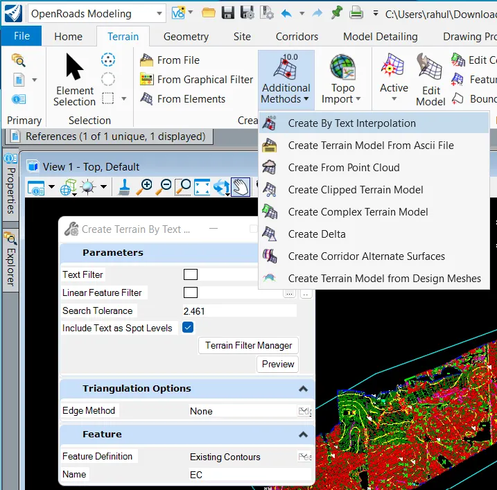
- Click on Terrain Filter Manager
- Create Text Filter using elements type as text
- Create Lines filter using element type line string
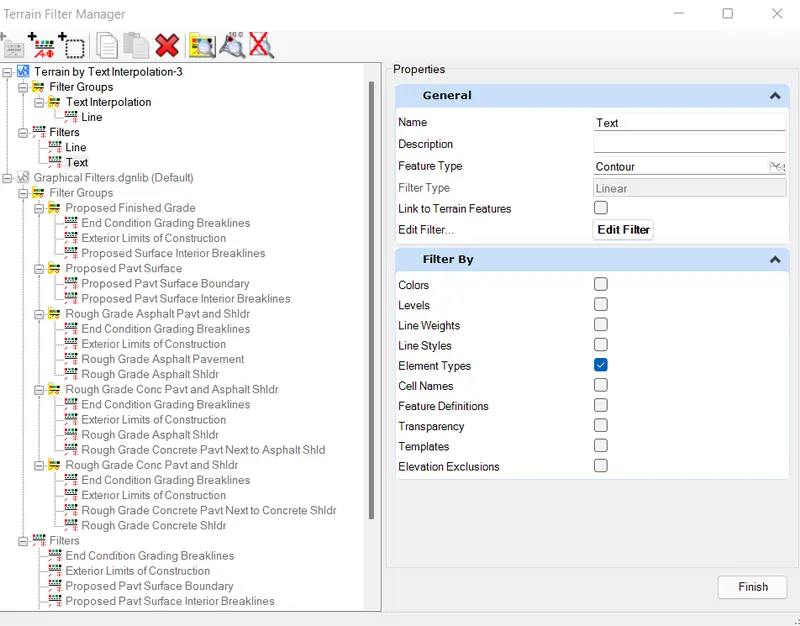
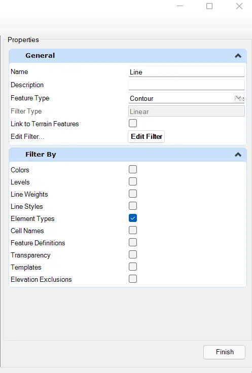
- Create filter group using only Lines filter created above
- Set all the parameters in the popup box
- Set edge method as Remove Slivers
- Feature definition as Existing Triangles
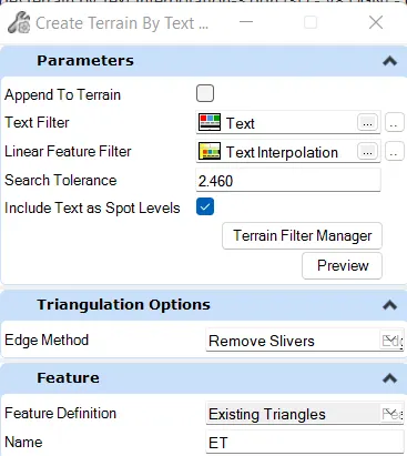
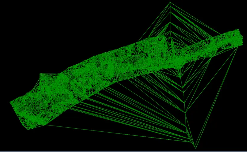
- Left-click to complete the process
From Elements
Step 1: Opening File
Open a New file with a 3D seed file
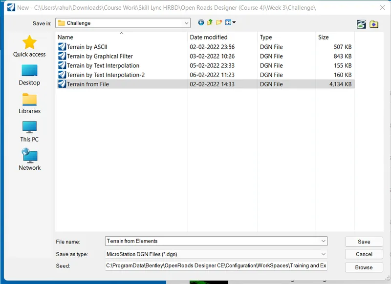
Set name as Terrain from elements and click save to open file
Step 2: Attaching Survey data
In-Home tab click on Attach tools and click on references
Click on Attach and select '3D_Survey Graphics file
Set attachment method as interactive
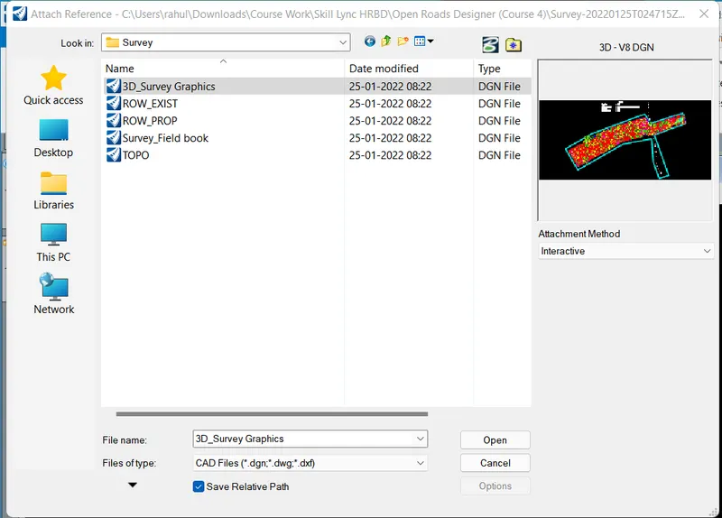
Click open and set the details as follows
Click ok and click fit view to view the file
Step 3: Terrain from elements
Click on Terrain From Elements
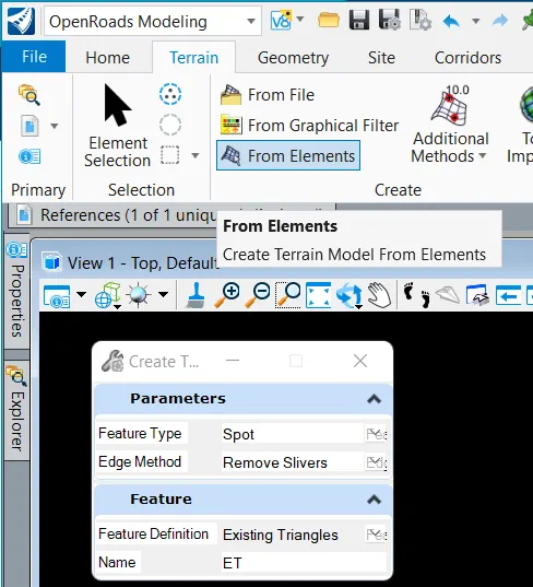
- Set feature type as Spot
- Set edge method as remove slivers
- Feature Definition as Existing Triangles
Go to the Home tab and click o Level display
- Click on the reference file
- Do Right-click and click on "ALL OFF"
- Select Layer 38 which is spots
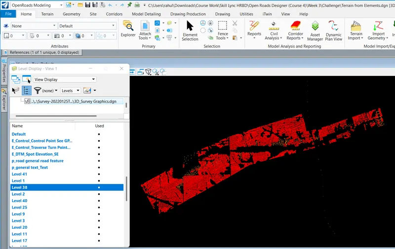
Go to Element selection by layer and click on Line to select all spots

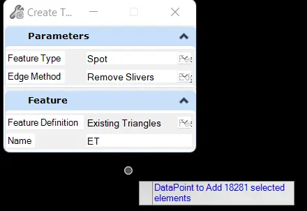
- We can see 18281 spots got selected
- Right-click to reset
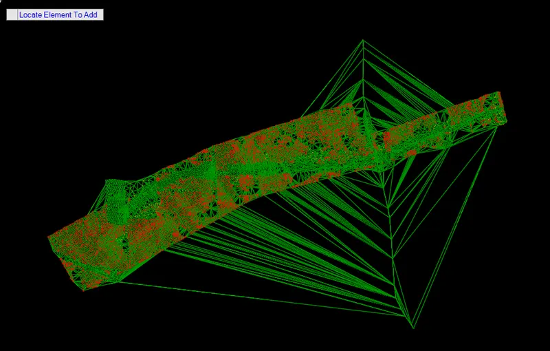
The resulting Triangles are as follows
Result:
The resulting Terrain models created are as follows
1. From file
2. By ASCII
3. By Graphical Filter
4. By text interpolation
5. By elements
2. Select the terrain model which you would be using for your entire design. (point to consider – dense triangulated, covering the area, no bad spots, etc.) with any one of the methods above to clear unwanted triangles, zero elevations points.
Aim: To Edit the TIN Network
Introduction:
Editing is terrain model is to remove the spots which are at unusual elevations which create unnecessary triangles and surfaces
Procedure:
Step 1: Open Terrain Model
Create a new dgn file using the '3D seed imperial' seed file
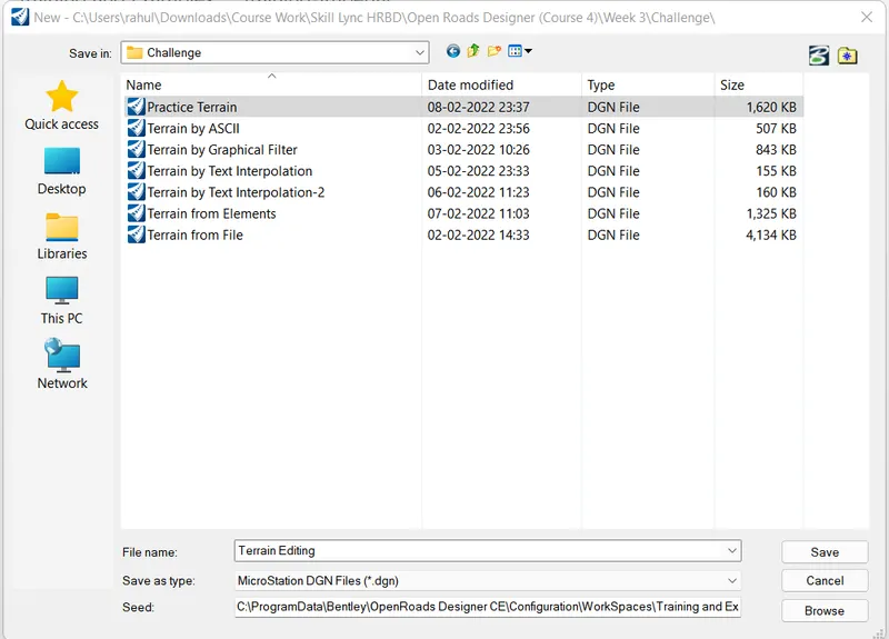
Set name as terrain editing
Open the Reference toolbar and attach the terrain from graphics elements created earlier
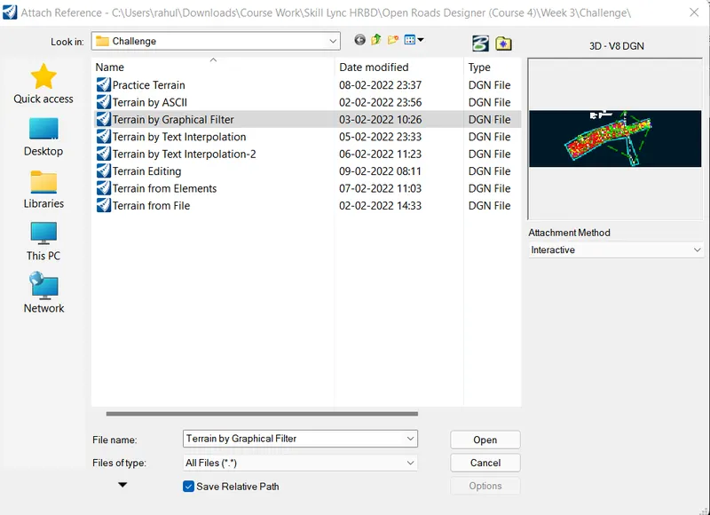
Click open and click fit view
Set overrides as yes
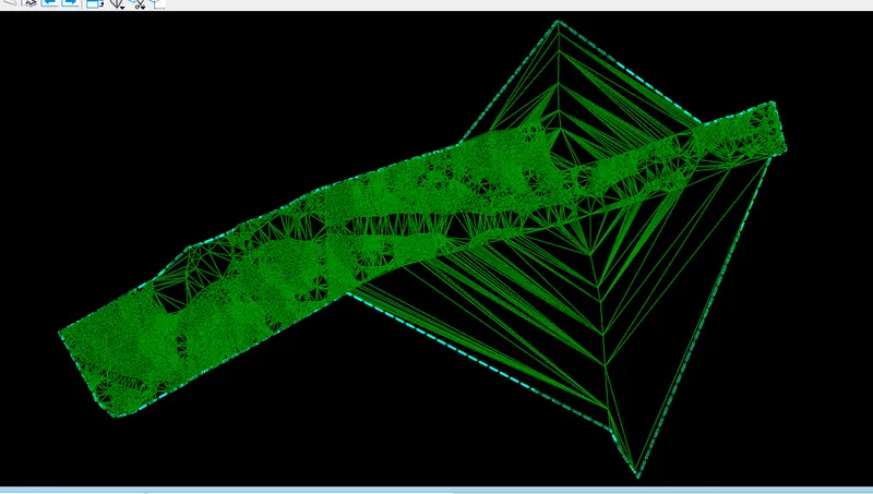
Step 2: Editing Terrain Model
Go to the Terrain tab click on edit terrain
Use various options and delete unwanted spots and triangle
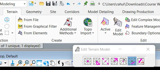
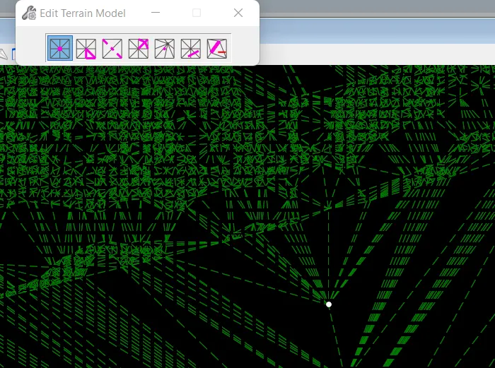
1. Remove spot
Hover over the spot until a white spot is visible and click to delete

2. Delete Edge triangles
Hover over the unwanted edge triangle to delete them as follows
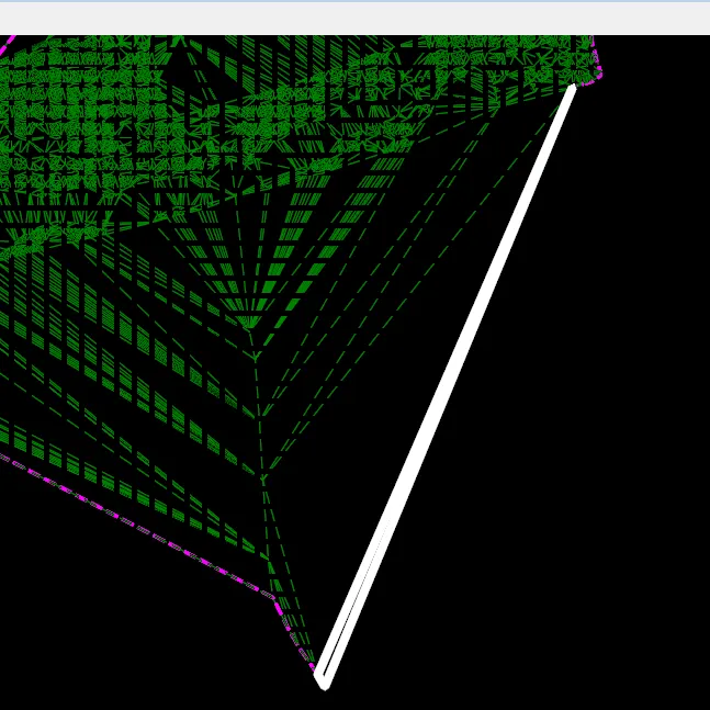
click to delete the triangle
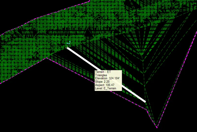
3. Swap triangle side
Select the triangle side to swap
4. Add Vertex
Hover over the area where a new vertex is needed and select the spot
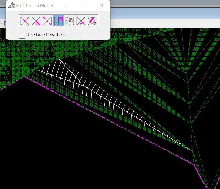
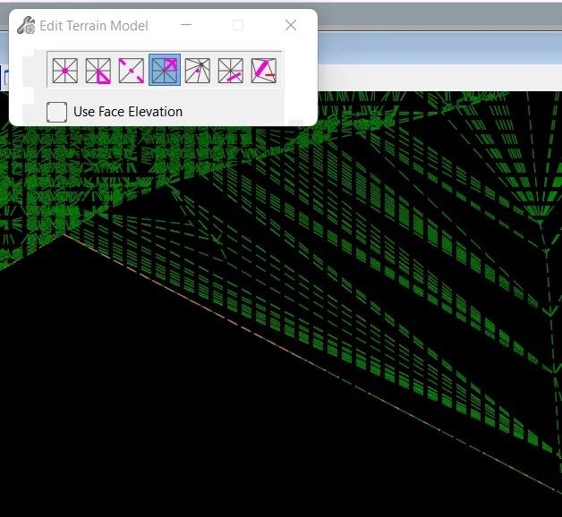
5. Move Vertex can be used to move the vertex
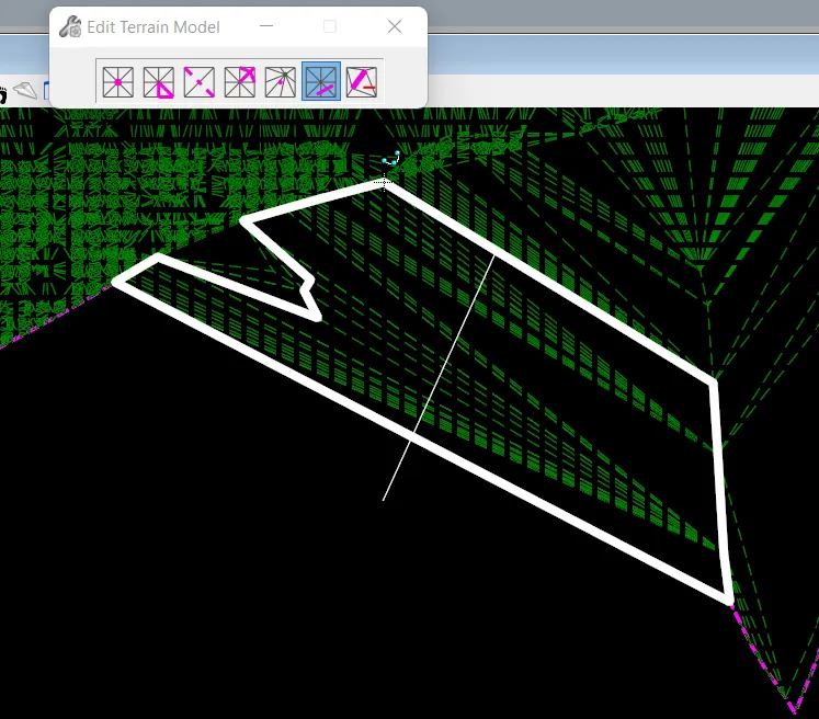
6. Delete triangle line is used to delete the unwanted lines of terrain created using a line drawn a specific direction
Result:
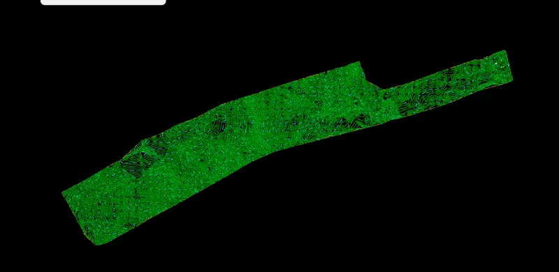
After removing all the unwanted spot and triangles the Terrain model is as follows
3. Export the terrain model to DTM, TIN, Land XML formats and save these in the Terrain folder of the data set.
Aim: To export the edited terrain model
Introduction:
The terrain model created can be exported to different file formats using Open roads designer which can be used as reference file attachments
Procedure:
Step 1: Open Terrain Model created
Open the Terrain editing file created above
Step 2: Exporting terrain model
- Select the terrain model and hover to view option and at the end export terrain model
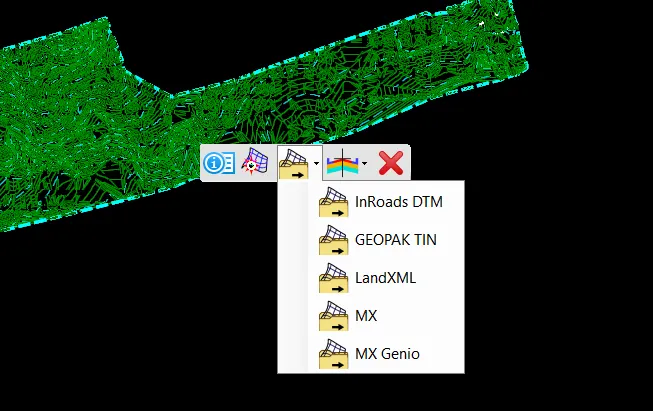
or
- Go to the terrain tab and click on export terrain at the end of the tab
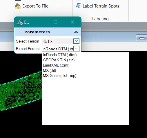
1. DTM
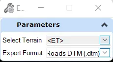
Select export format as Inroads DTM
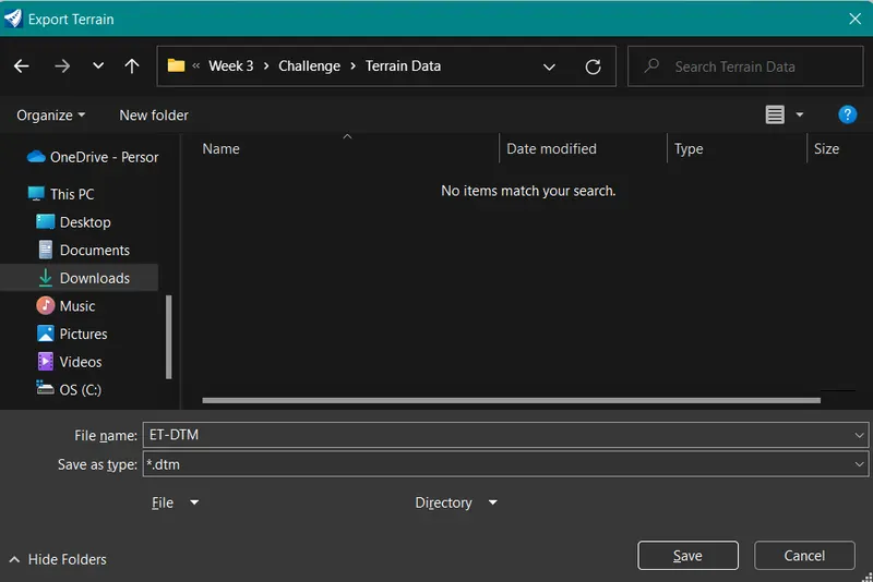
Click save
2. TIN
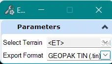
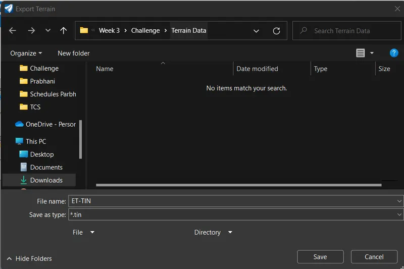
Click Save
3. Land XML
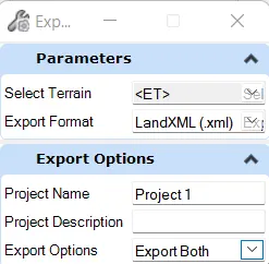
- Set project name as Project 1
- Export option as 'Export both triangles and features
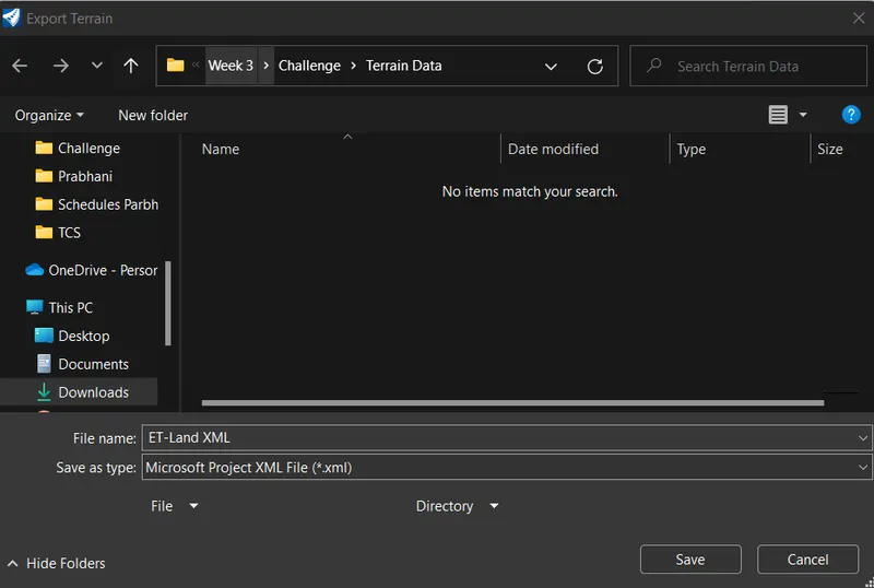
Clcik Save
Result:
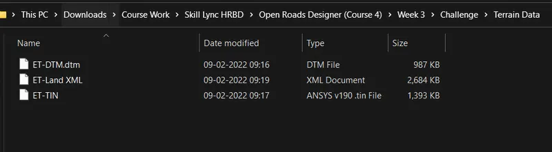
The data set of exported terrain models is as follows
4. Create a new 3D DGN and import the TIN, DTM XML from above.
*(For reference: Surface to Grid factor = 1.00:1.00012)
Aim: To create a new 3D DGN and import the TIN, DTM XML from above.
Introduction:
Importing the terrain model exported in the above
Procedure:
Step 1: Open New File using 3D seed file
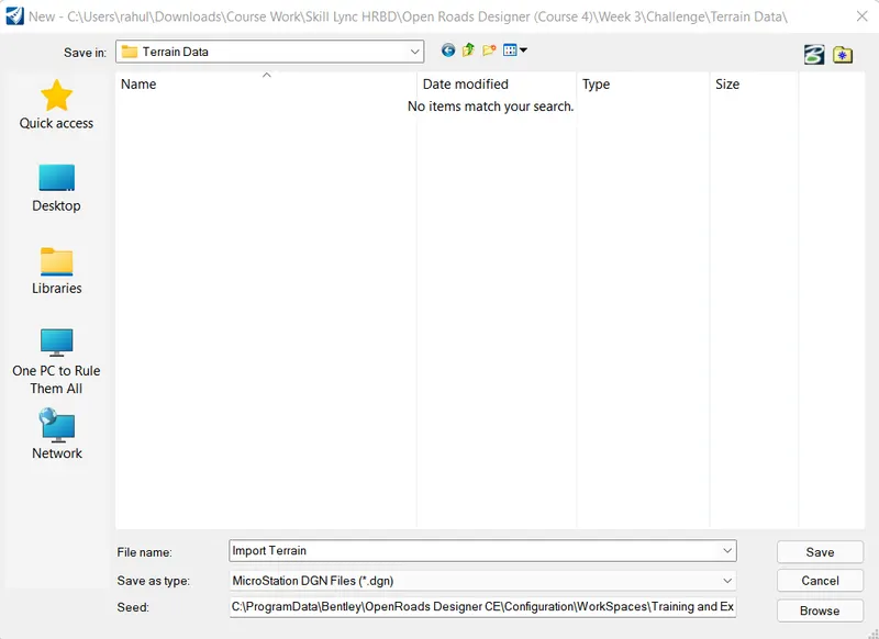
Step 2: Import Terrain
Go to the terrain tab and click on Import from file
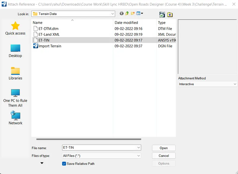
Click on ET-TIN and click Open
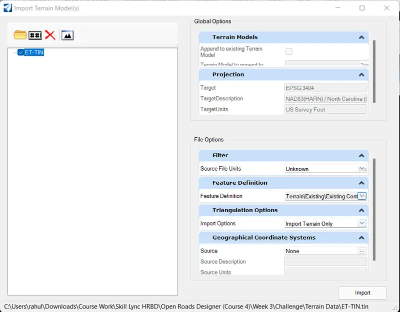
- Set Feature Definition as Existing Contours and Triangles
- Import options as Import terrain Only
- Click import
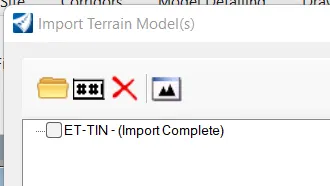
Follow the same procedure for all types of data
Result:
The imported terrain model is as follows