Week 5 Challenge
Challenge 5
Submitted by Kanala Rahul Reddy
1. Create a new DGN file for horizontal geometry. Draw tangent lines with various methods. Insert curves in between them as well at the ends. Apply feature definitions to all these elements.
Aim: To create a new DGN file for horizontal geometry using various methods
Introduction:
Horizontal alignment includes a road comprising a series of straight lines known as tangents with the provision of curves to change direction. It also provides for the design of superelevation, extra widening, set back a distance, transition curve design, etc.
Procedure:
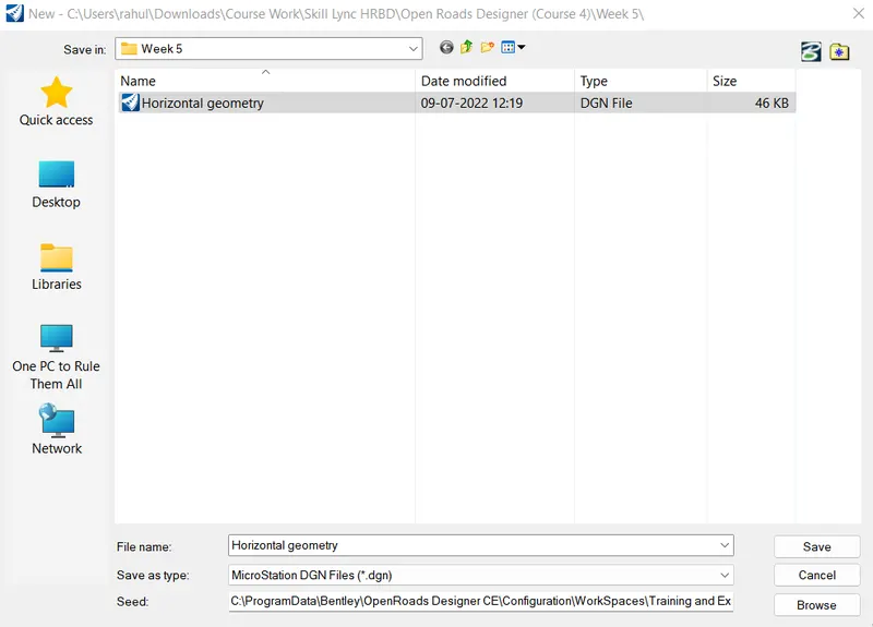
Step1: Open a New DGN file
Open "Open Roads" and Click on the new file and set seed file 2D seed DGN and name as Horizontal geometry
Step 2: Creating Geometry using Lines
Go to the Geometry tab and click on the Line dropdown
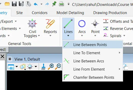
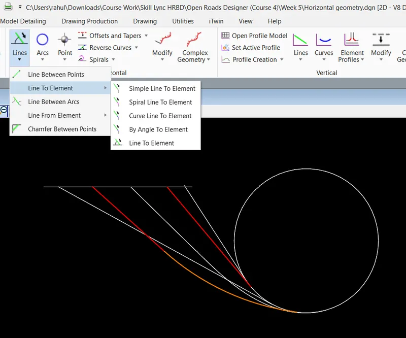
After trying all options result is as follows
A. Line Between points

B.Line to Element
using all types of line to element
C. Line between Arcs
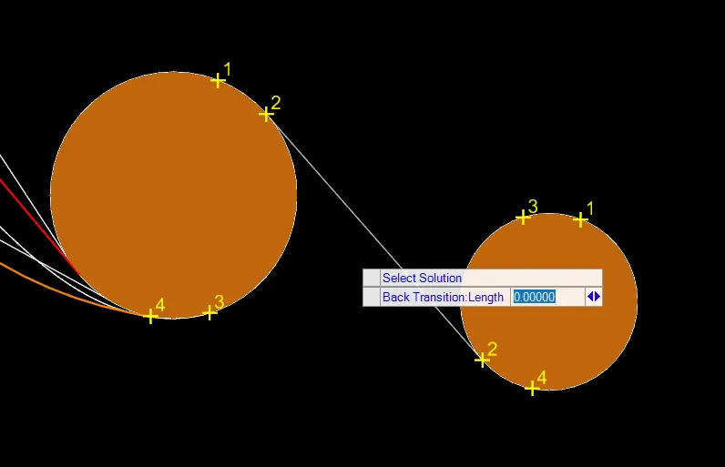
D. Line between Elements
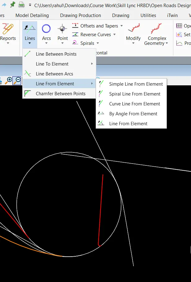
E. Chamfer between elements
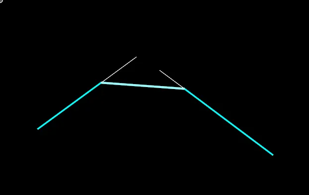
Step3: Creating geometry using curves
- Draw some lines using methods to draw lines
- Use the various method of drawing using arcs between elements as shown below
- add feature definition Geombasesline for all the elemets
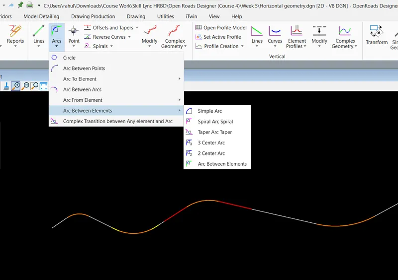
Result:
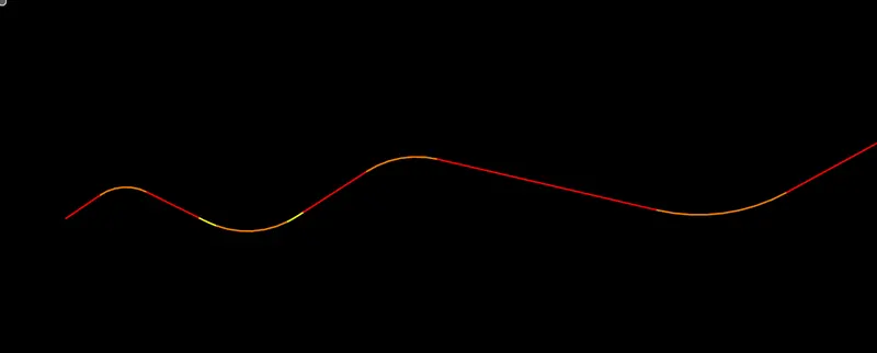
- Go to complex geometry and click on the complex by element
- Set method as automatic
- Set feature definition as geom_baseline and name as CL_alignment as follows
- Click on the start of geometry created
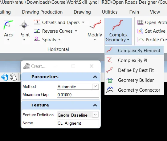
Complex by element is as follows
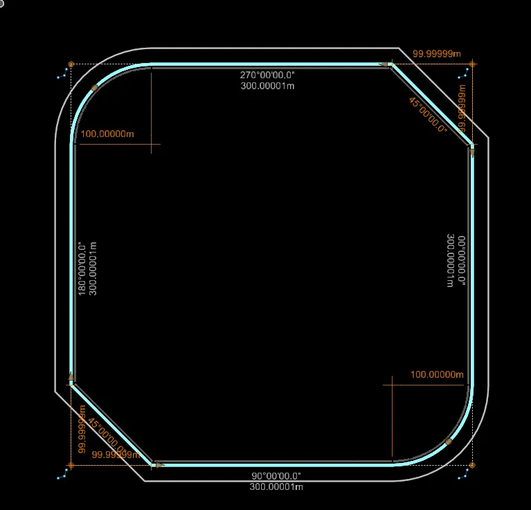
2. Create a square of 500’ side with fillets at 2 ends and chamfer at other two. Make complex. Offset this shape inside 5’ and outside 20’. Apply 3 different feature definitions for each of these shapes.
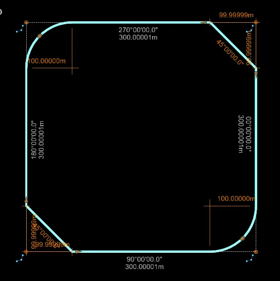
Aim: Create a square of 500’ side with fillets at 2 ends and chamfer at other two
Introduction:
A Feature Definition controls how each feature is displayed and how it interacts with various tasks. The first time you use a Feature Definition it is copied into your active DGN and can then be modified.
Procedure:
Step1: Open a New DGN file
Open "Open Roads" and Click on the new file and set seed file 2D seed DGN and name as Horizontal geometry
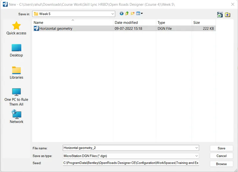
Step 2: Creating Square
Go to the Geometry tab and click on line btw points
- Set let as 500m and angle as 90
- set feature definition as Geobaseline CL as follows and draw a line as follows
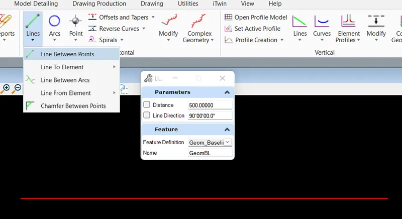
Now repeat the same with angles 0, 270, and 180 degrees by snapping endpoint of the earlier line and the result is as follows'
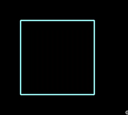
Change feature definition to Boundary_Property_Line
Step 3: Chamfer and Fillet
Go to the "Line" dropdown and click on the Chamfer between points
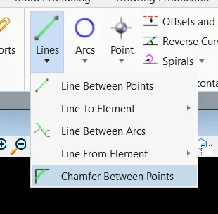
Go to "Curve" drop-down and click Arc between elements and simple arc
- Set radius as 100m
- Feature definition as boundary_propertyline as follows
- The trim method as Both
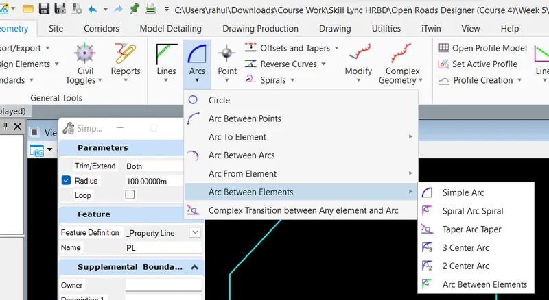
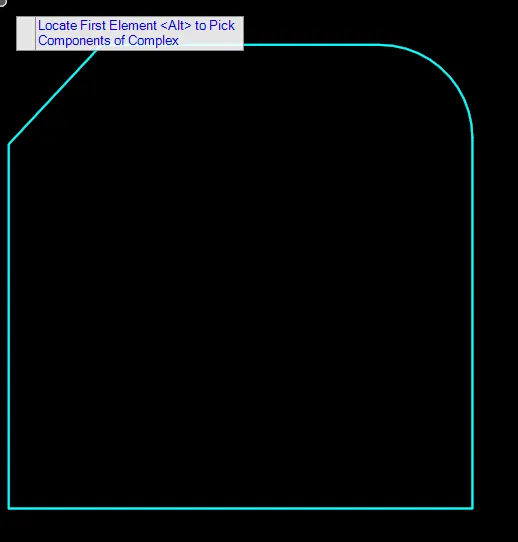
Select two adjacent lines draw and set the Fillet as follows
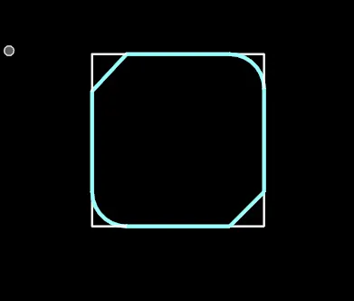
Repeat the above method for the bottom part as well and the result is as follows
Step 3: Creating Offsets
Go to complex geometry and click on the complex by element
- Set method as automatic
- Set feature definition as Boundary_propertyline and name as Borderline as follows
- Click on the boundary of created
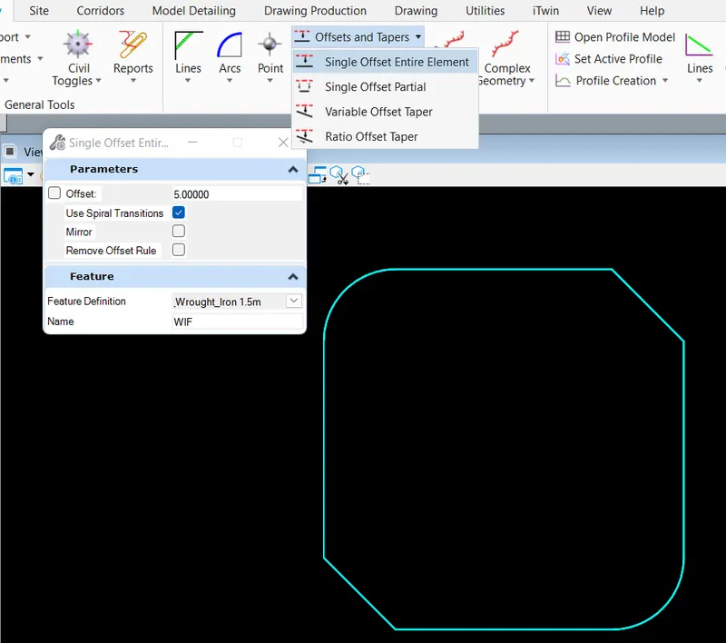
Go to " Offsets and Tapers" and select single offset entire element
- Set offset as 5'
- set feature definition as Fence as follows
- Select the boundary element created above and click inside of the element
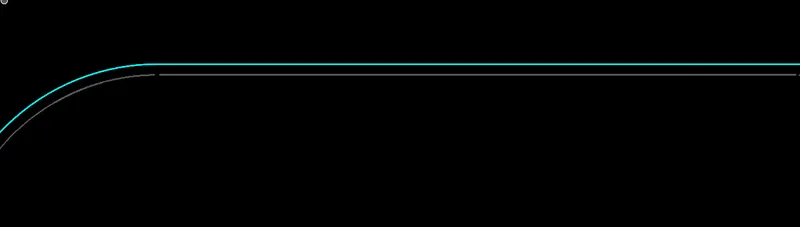
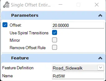
Go to " Offsets and Tapers" and select single offset entire element
- Set offset as 20'
- set feature definition as Fence as follows
- Select the boundary element created above and click inside of the element
Result:
Result after creating the offsets is follows
3. Create any point featured element along the outmost shape by point tools.
Aim: Create any point featured element along the outmost shape by point tools
Introduction:
Point feature
Procedure:
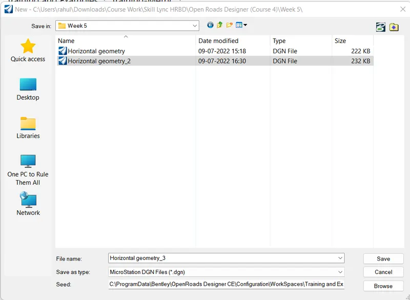
Step1: Open a New DGN file
Open "Open Roads" and Click on the new file and set seed file 2D seed DGN and name as Horizontal geometry
Step 2: Creating point featured element
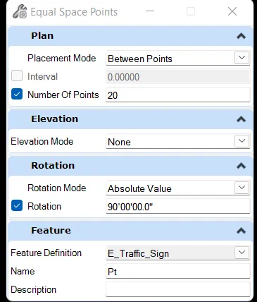
A. Between points
Go to the Geometry tab and click on Point
- Set method as Between Points
- Number of points as 20
- Rotation as 90
- Feature definition as Traffic sign as follows
Draw 2 points of some distance and observe the gap between signs
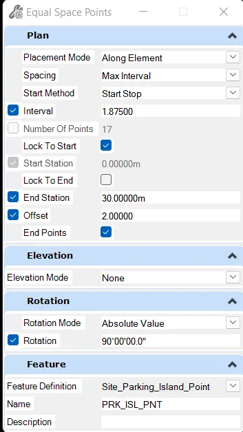
B. Along Element
Draw a line of 30m using a Line between points
Go to the Geometry tab and click on Point
- Set method as Along Element
- The spacing method as Max interval
- Start method as Start-stop
- Set interval as 2
- Start station as 0+000
- End Station as 30 and offset as 0
- Rotation as 90
- Feature definition as Site parking Island point
Select the element created
Result:
The result after creating is as follows
Between Points

Along Element