Week 3 - 2D meshing for sheet metal
PREPROCESSING OF HOOD MODEL USING ANSA
AIM:- To Mesh Hood Model as per the given quality criteria.
PROCEDURE:-
Process flow diagram(PFD)
1. Geometry cleanup
2. Topology activity
3. Midsurface generation
4. Set PID
5. Define mesh & quality criteria
6. Mesh Generation
7. Mesh flow & Quality improvement.
1. Geometry Cleanup
Once we import the model to ansa, we need to check for geometrical errors like needle faces, triple cons & unchecked faces.
We need to do check geometry by -Tools-Check-Geometry option available on the desk.
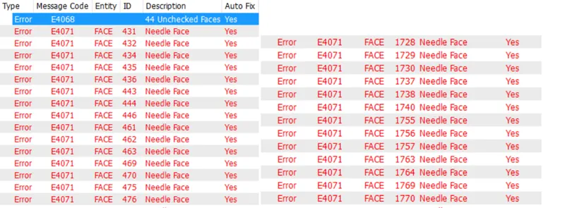
These errors can be fixed by using auto-fix option or by manual mode.
Autofix option:-By using the auto fix option, ANSA automatically fixes the error.
Just one has to right-click on the error & click fix.
Manual mode- To fix the error manually, one has to right-click on the error & press the show only option.
By this ANSA will only show the error place. We can also use the Boolean operation to know the exact place of error.
2. TOPOLOGY ACTIVITY
By topology word, we understand how features & different faces are connected to each other.
Perimeter & macros length is defined as per the quality criteria.
Length between the cons should satisfy the minimum & maximum length criteria otherwise it will result in elemental failure.
Defeaturing- If length criteria are not satisfied then one can opt for the defeaturing process.
It is simply compromising for one feature to save another features.
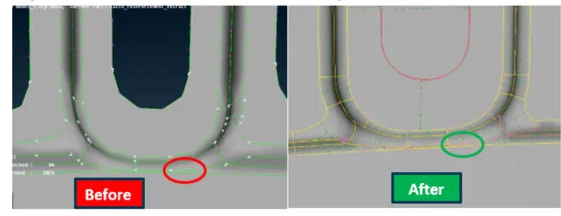
In the above model, there are two feature lines close to each other where the elemental length will fail.
Here we can use defeaturing to satisfy the length criteria.
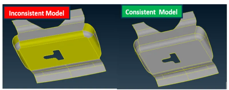
In topology activity, the orient option is used.
Orientation is indicated by grey & yellow colour surface.
Grey surface is assumed as positive &yellow surface as negative
3. MIDSURFACE GENERATION.
As this component is sheet metal, it will have a uniform thickness in every place.
Midsurface is the middle face or layer between the two surfaces having a uniform thickness.
In ANSA mid surface can be generated in two ways-
1. Manual process(Offset)
2. Auto mid option
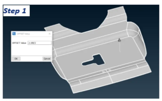
Manual process(Offset)- By offset option mid surface is generated by clicking on the surface one by one & giving the offset distance. (Thickness value/2).
Note- One has to be careful about the direction from which offset value is being taken & then +ve or -ve value is inserted.
Once the mid surface is generated we should use the topo option to link the associativity of the different boundaries.
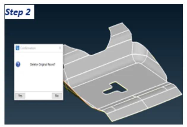
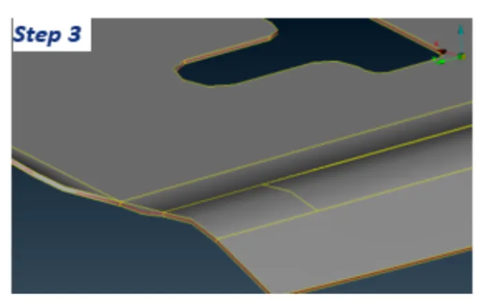
NOTE- It is advised to use the manual mid-surface generation option in your initial phase.
Automid option needs to be avoided.
Automid option-This command automatically generates the mid surface by deleting the parent surfaces.
To generate the mid surface click faces-Select mid surface & select the surface where you want to generate the mid surface & then press the middle mouse click button.
ANSA will highlight one side face in red color & another side in green colour.
The thickness area will be highlighted in blue colour, then press again middle mouse button & midsurafce will be extracted.
4 SETPID
After generating the mid surface, a PID ie .a property ID need to be assigned to the surface.
Defined thickness & material need to be mentioned.
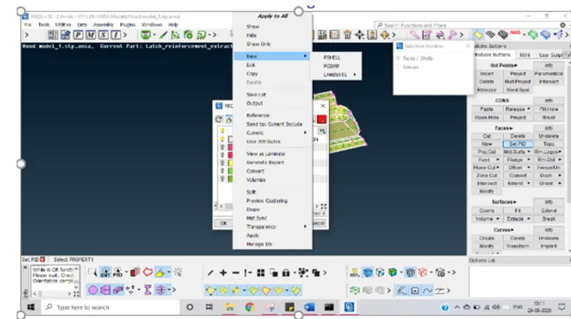
To assign PID click on PID, select faces & press middle mouse click.
Property window will open, click on window NEW- PSHELL.
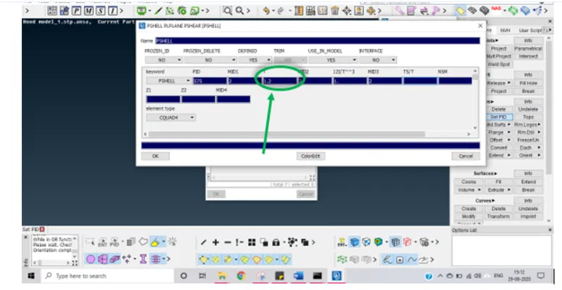
Here the thickness value needs to be assigned.
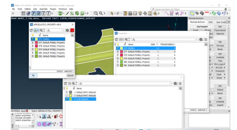
Now switch to PID mode from ENT mode to check if PID is applied to the model.
The color of the model will change the same as defined in the PID.
5. Define mesh parameters & quality criteria.
Mesh parameter is available in the utility option. Here we need to define parameters like Target length, Min. Max length.
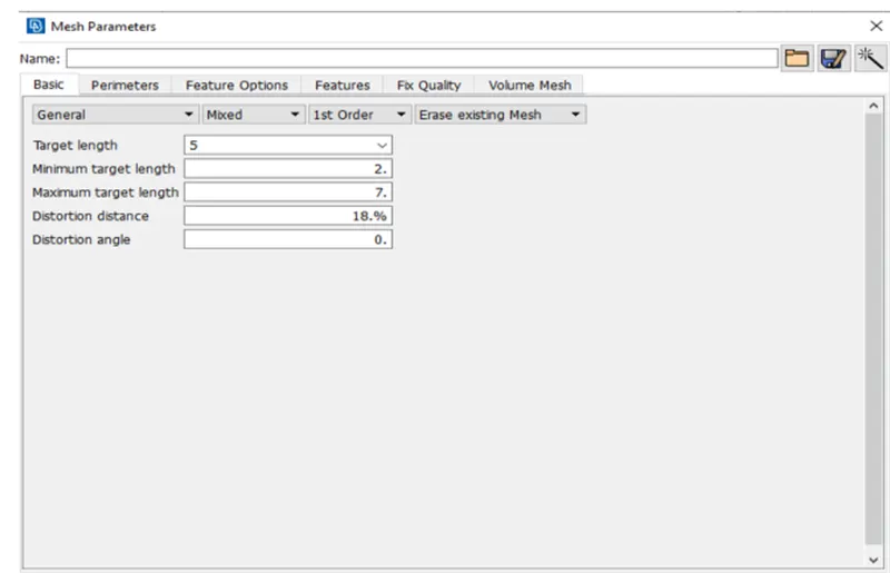
Now quality criteria are to be defined as per the requirement. Our requirements for this model are-
| S.No | Quality Criteria | Value |
| 1 | Target/Average length | 5 |
| 2 | Minimum Length | 2 |
| 3 | Maximum Length | 7 |
| 4 | Aspect | 3 |
| 5 | Warpage | 15 |
| 6 | Skewness | 45 |
| 7 | Jacobian | 0.7 |
| 8 | Minimum Quad Angle | 45 |
| 9 | Maximum Quad Angle | 135 |
| 10 | Minimum Tria Angle | 30 |
| 11 | Maximum Tria Angle | 120 |
| 10 | Tria Percentage | 15 |
6. MESH GENERATION
Mesh generation is the process of discretizing a model into small elements.
One should use the Best mesh option for the meshing process.
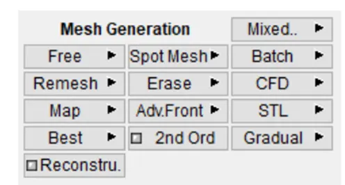
2D mesh has two types of elements-
1. Quads
2. Trias.
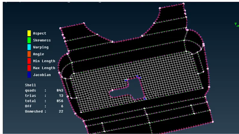
Meshing process- We should use the best mesh from the mesh generation option & select the face to be meshed.
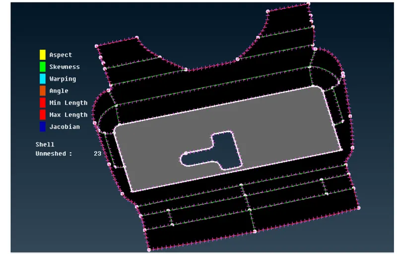
Now pressing the middle mouse will generate the mesh.
70. MESH FLOW & MESH QUALITY IMPROVEMENT
After meshing, a lot of elements will fail for quality criteria.
So, quality improvement is the most important criterion for good mesh flow.
We have the following options in ANSA to mesh & quality improvement & are as follows-
Reconstruct-This command will eliminate max. no. of error present in the messed model.
It will reconstruct the mesh, alter its element & node & try to minimize the tria percentage by taking care of quality criteria.
Reconstruct is done in the following ways-
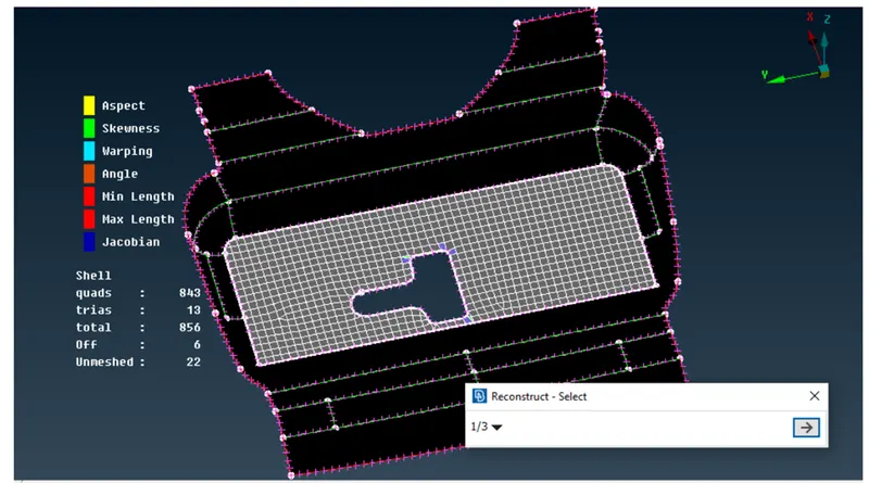
Step 1- Select shell mesh-RESCONSTRUCT- Select area to be reconstructed.
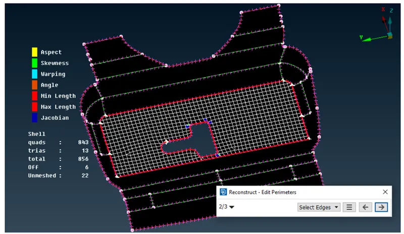
Step 2- Select the edge & press, ok & it will preview the mesh.
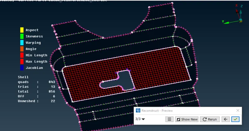
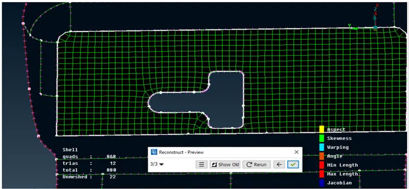
NOTE- Mesh can also be improved by changing the perimeter numbers.
2. Split, Swap & Join-
Split- This command is used to split the cell into two 2parts.
Join- Join option is used to join the two tria sharing the same edge to convert it into quads elements.
The swap option is used to swap the tria elements from one place to another.
Smooth Option:-This command will improve the mesh flow by proper spacing the element without change in element arrangement.
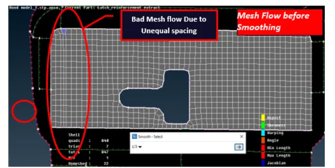
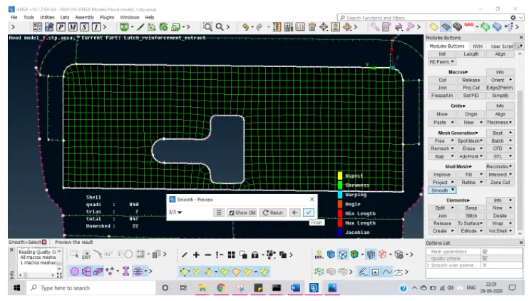
Now above mesh is equispaced after using the smooth command.
One should use smooth command after every meshing option.
SOME BEST PRACTICES TO GET BETTER MESH FLOW.
1. Two tria elements should not be connected to each other.
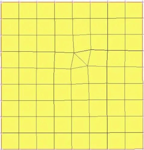
By using the join command, we can convert two end-to-end tria in quad element.
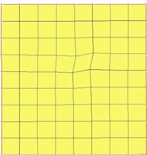
2. Two opposite tria near to each other should be avoided.
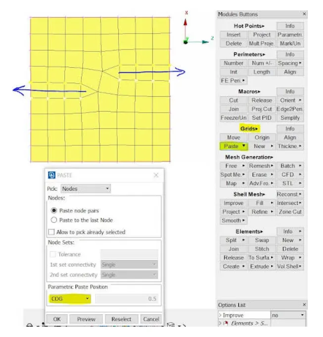
Two opposite tria element is present in the mesh.
By using the paste option these tria can be taken outside the free edge & used to move tria in the backward direction.
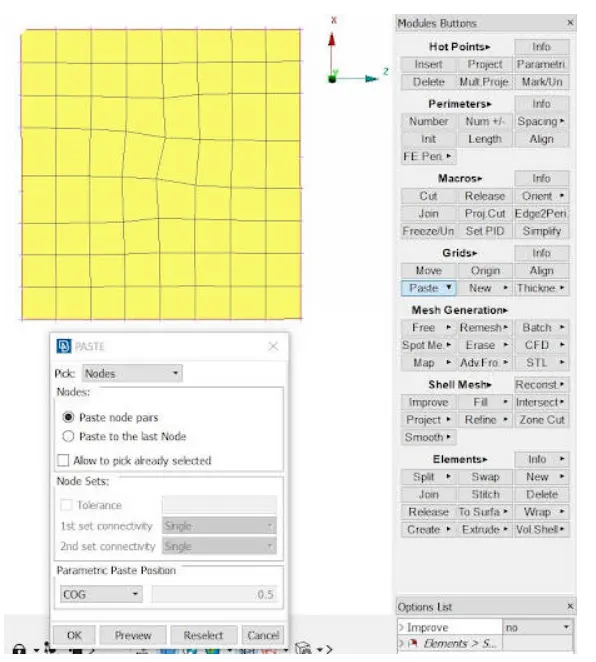
Here 2 opposite tria are removed by the paste option.
By using the split-Edge option trias can be taken outside the free edge & moved in the forward direction.
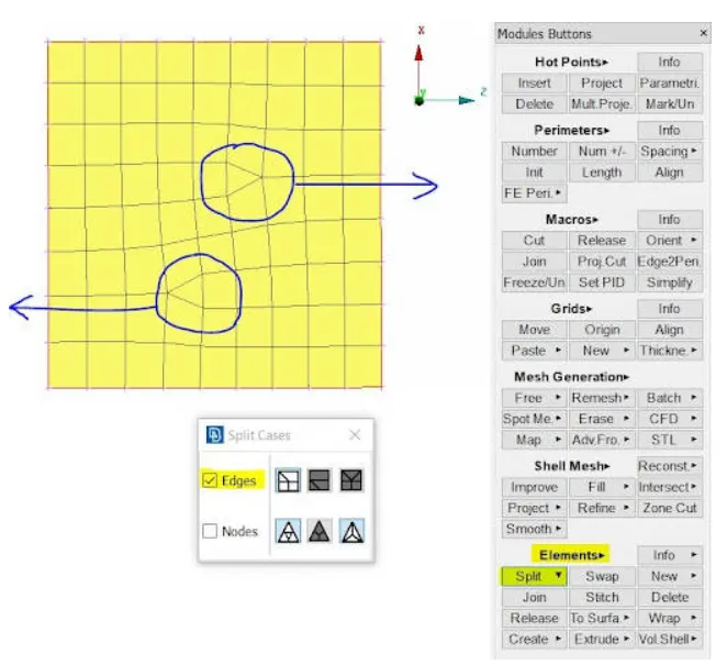
Here 2 opposite trias are present.
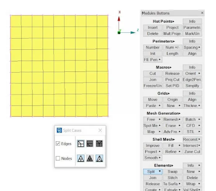
Two opposite trias are removed by the split option.
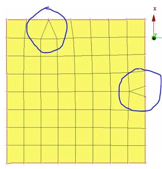
Avoid tria element at the outer edge.
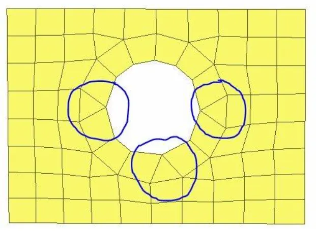
Avoid tria element connected to the hole-free edge.
Finally Active draw shell as solid from quality tab menu.
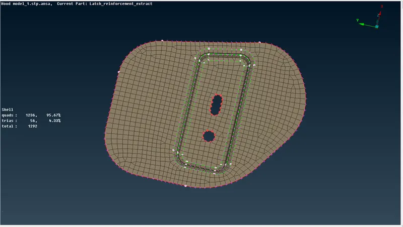
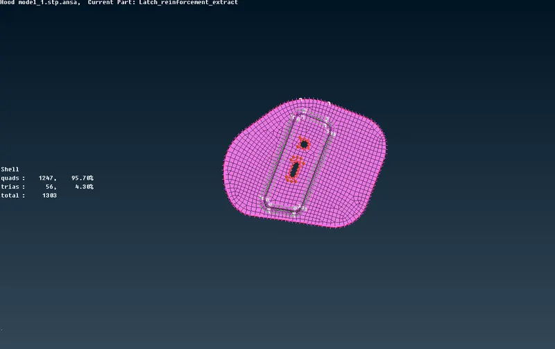
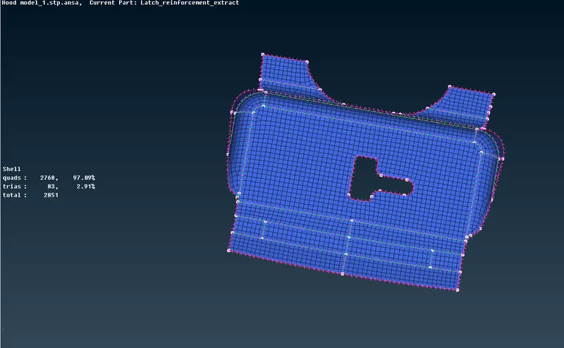
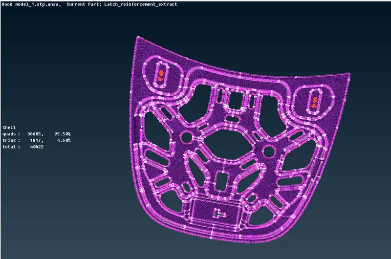
Below are the various mesh model shown:-
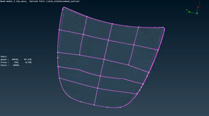
LEARNING OUTCOMES:-
1. After working on this model, i got to know user interface of ANSA.
2. Use of various Boolean command like AND, OR, NOT, INOT Etc.
3. Perform topo & geometry cleanup.
4. Midsurface extraction & Assigning PID.
5. Meshing Generation for any model.
6. Various option to improve mesh flow.
CONCLUSIONS:-
During working on this model, i got to understand the followings:-
1. After importing cad model from some other software to ANSA, some geometrical error occurs.
We have to fix these errors by checking the geometry .
2. Effect of triple cons in model.
3. Effect of Trias & rotating quads in mesh flow.(Avoid trias & rotating quads as much as possible as it disturb the flow of forces).
4. Effect of defining quality criteria & its impact on mesh.