Week - 3 Drop test Challenge
DROP TEST OF AN CELL PHONE AND THE PLATE
AIM:
- To perform a drop test simulation of a cell phone dropped on a plate under initial velocity using LS-Dyna.
OBJECTIVE :
- To create the simulation file (input file ) from the given K format type of file.
- To create the material card.
- To create a section card.
- To assign material and section card to the part.
- To create the boundary conditions for plate.
- To assign initial velocity to the phone.
- To assign control termination card.
- To create a contact interface between cell phone and plate.
- To define the output database as both binary D3 plot and ASCII.
- To checkup the model and run the simulation.
DATA BASE :
- K format type of drop test meshed file.
- *INITIAL_VELOCITY card is to be used to given velocity specifications for the cell phone.
- Consider appropriate magnitude of velocity between the plate and cell phone.
- Ignored the orientation of the cell phone and plate.
SOFTWARE USED :
Solver tool - LS-Prepost 4.7.17 and LS-Run 1.0.100838
PROCEDURAL STEPS :
STEP 1 : Import the file
- imported the f format type of drop test file using LS-Prepost software.
- File > Import > LS-Dyna keyword file > browsed to selected the K type of file > imported it.
Imported the k file of drop test
STEP 2 : Check the keywords
- In order to check the keywords contained in the file we have to follow the below step
- Side bar > model and part > keyword manager > checked the model.
- Both shell and solid elements are presented in the model .According to analysis solid elements only needed other shell elements remove from the model
Keep solid elements Only
STEP 3 : Create the material card
- To assign the material card for cell phone and floor by the following steps.
- Side bar > model and part > keyword manager > MAT > all > selected the required materials for the phone and plate parts.
- For cell phone part has assigned the material is 024 PIECEWISE_LINEAR_PLASTICITY and plate part has assigned the material is 020 RIGID.
Material card creation for cell phone
Material card creation for plate
Both material Properties values are followed by the Kg /mm/ms unit system
Where,
MID-material identification
RO - Mass density
E- youngs modulus
SIGY - Yield stress.
ETAN - Tangent modulus
PR - poissons ratio.
STEP 4 : Create the section card
- For analysing the solid elements will use section solid.
- In this section element formulation ,integration rule , nodal thickness and cross sectional properties are defined.
- Created the section solid for cell phone and section solid for plate.
- Side bar > model and part > keyword manager >all > solid > created the new SECIDs for both parts.
Section card for cell phone
Section card for plate
STEP 5 : Assign the material card and section card to the parts.
- Already assigned the material card and section card for cell phone and plate , now we have to assigned the both cards to their respective parts.
- Side bar > model and part > keyword manager >model > part > assigned the MID and SECID cards to their respective parts.
Assigned material card and sectionn card to the cellphone
Assigned material card and sectionn card to the plate
STEP 6: Create the boundary condition for plate
- Before creating the boundary condition we have to create the node set identity for plate.
- In order to create node set id by the following steps.
- Side bar > model and part > create entity > set data > set node > selected the nodes by area in plate > node set created for plate > tilte name as plate_node > done.
- Side bar > model and part > create entity > set data > set node > selected the nodes by area in cellphone > node set created for cellphone> title name as cellphone_node > done.
Created Node set for cellphone and plate
STEP 7: Assign the boundary condition to the plate.
- Assigned the boundary condition to plate is by using, side bar > model and part > create entity > boundary > Spc > create > set > all fix [111111] > specify the node set id value for plate is 1 > selected the nodes by area > apply > done.
Assigned boundary condition to the plate with respective nodeset of plate
ii. To check the assigned boundary condition to the plate is Side bar > model and part > keyword manager > boundary > spc > apply > done.
Checked boundary condition to the plate
iii. To check the created nodeset id for the plate and cellphone parts by using , Side bar > model and part > create entity > set node > able to see the created nodeset ids for their respective parts.
Checked nodeset id for the plate and cellphone
STEP 8 : Assign the initial velocity to the cellphone
- Define nodal point velocities using nodal set ID's
- Inorder to assign initial velocity, already created nodeset id for cell phone .
- Create initial velocity to selected set nodes for ceel phone.
- Side bar > model and part > keyword manager > initial > velocity > selected the nodeset id for cell phone > specify the initial velocity value is 6 mm/ms > accept and done.
Assigned initial velocity to the cellphone
v. In order to check vector direction of applied velocity by the following steps.
vi. Side bar > model and part >display entity > selected velocity > displayed vector direction of the applied velocity.
Vector representation of initial velocity to the cellphone
STEP 9: Assign the control termination card
- The main purpose of control termination card is to stop the job.
- In order to assign the control termination card by the following steps.
- Side bar > model and part > keyword manager > control > termination > specify termination time is 5ms > aceept and done.
Assigned the control termination card
STEP 10 : Create a contact interface between the cellphone and plate.
- The keyword *CONTACT provides the interaction between disjoint parts.
- Before creating contact card , we have to create set data segment for cellphone and plate.
- Define a set of segments with optional identical or unique attributes.For 3 dimensional geometries a segement can be triangular or quadrilateral.
- In order to create set of segments by the following steps.
- Side bar > model and part > create entity > set data > *SET_SEG > selected the elements by area > plate_segment created.
- Side bar > model and part > create entity > set data > *SET_SEG > selected the elements by area > cellphone_segment created.
Creation of cellphone_segment and plate_segment
vii. In order to create the contact card by the following steps.
viii. Side bar > model and part > keyword manager > CONTACT > selected AUTOMATIC SURFACE TO SURFACE > selected plate_segment as a master and cellphone_segment as a slave > accept & done
Creation of contact card between cellphone and plate
STEP 11 : Define the outputdatabase as both BINARY D3PLOT AND ASCII
- DATABASE_BINARY_D3PLOT ensures d3 plot files which its stores stress strain contour of the entire deformed model.
- In order to create the DATABASE_BINARY_D3PLOT by the fllowing steps.
- Side bar > model and part > keyword manager > database > select DATABASE_BINARY_D3PLOT > provide DT value is 0.1 is a time interval between output states > accept & done.
Define the DATABASE_BINARY_D3PLOT
iv. ASCII can generate different outputs such as force generated in a contact like total energy and material energy etc.
v. In order to create the ASCII by the fllowing steps.
vi.Side bar > model and part > keyword manager > database > select ASCII_option > check GLSTAT DT value is 0.1 and MATSUM DT value is 0.1 > accept & done.
Define the ASCII database
Where, GLSTAT is Global statistics and energies.
MATSUM is part energies.
STEP 12 : Model checkup
- The model is checked for any errors before solving using model checker.
- After all the errors are cleared, the drop test setup is saved and is ready to run in LS DYNA manager for solving the scenario.
- Warnings we can ignore . once model checkis run , it will look like as shown in picture below.
Model checkup on created keywords
STEP 13 : Run the simulation
- To run the drop_test_cellphone_plate file using LS-run by the following steps.
- Title bar > file > run LS-dyna > runned the drop_test_cellphone_plate file > achieved normal temination. it means the model is ready for post-processing.
- During simulation run window will popup as shown in picture below
Runned the simulation K file of drop test
STEP 14 : Post processing
- In order to see simulation results , we have to open output file in LS-Prepost by the following steps.
- In LS-prepost -Title bar > file > open > LS -Dyna binary plot > selected the d3 plot file > visibled to see animation file.
- For plot the stress contour , go to sidebar > post >fringe component > selected in which results need for analysing the problem.
- For energy plot results , go to side bar > post > ASCII > selected in which enegy results (Glstat and Matsum) need for analysing the problem.
(1) Contour plot of von misses stress of drop test of an cellphone and plate
From this vonmisses stress plot, developed Maximum stress = 0.01957 kg/mm^2
(ii) Energy plot of drop test of an cellphone and plate
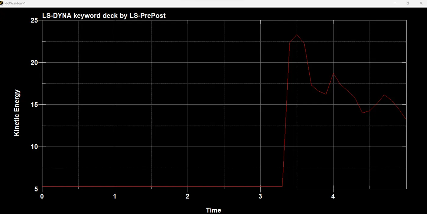
From this plot ,
- Initial velocity is maximum therefore kinetic energy is also maximum .
- But during the cellphone impacted on the plate , the kinetic energy obsorbed by the part and it decreases.
- Simulataneously before the cellphone impacted on the plate the internal energy in minimum, then after during the cellphone impacted on the plate the internal energy obsorbed by the part and it increases.
RESULT :
- Performed a drop test simulation of a cell phone dropped on a plate under initial velocity using LS-Dyna.
- Maximum effective stress is 0.01957 kg/mm^2.
- Energy plot has been successfully as per the required simulation outputs.
LEARNING OUTCOMES:
In this week 3 challenge i came to know,
- How to do create the material card.
- How to do create a section card.
- How to do assign material and section card to the part.
- How to do create the boundary conditions for parts.
- How to do assign initial velocity to the part.
- How to do assign control termination card.
- How to do create a contact interface between the parts.
- How to do define the output database as both binary D3 plot and ASCII.
- How to do checkup the model and run the simulation.
- How to do create the simulation file (input file ) from the given K format type of file