Week 12:Project 2-Meshing of Rear Wheel Holder challenge
OBJECTIVE:- Follow the below-mentioned quality criteria, mesh the component given below and assign thickness:-
Target Element Length = 5 Units
| S.N | Quality Criteria | Value |
| 1 | Aspect Ratio | 5 |
| 2 | Skewness | 45 |
| 3 | Warping | 15 |
| 4 | Taper | 0.5 |
| 5 | Min. Length | 2 Units |
| 6 | Max. Length | 8 Units |
| 7 | Min angle Quad | 45 |
| 8 | Max angle Quad | 135 |
| 9 | Min angle Tria | 20 |
| 10 | Max angle Tria | 120 |
| 10 | Tria % | 10 |
Procedure:
1. To begin with the meshing process on the model, the very first step is to geometrically clean the model after we import it. There might be presence of some errors during the importing process. An added step during the geometric clean up is the process of defeaturing all the fillets that will fail for the minimum length criteria when we mesh on it.
So we can either remove these kind of fillets in the parent surface or we can remove them seperately in the mid-surface.


By this process, we can make the extraction of mid surface much more easier and the improve the mesh flow overall. After the Defeature command is done, we then need to switch to the surface view to "By Topo" to view for any free edges and then thus resolve them if necessary.
2. After the Geometry clean up is performed, then we go on to extract the mid surface of the component. Since the component is more or less of an uniform thickness, we can use the Midsurface command available in the Geometry tab. In the midsurface command, we need to change the extraction option to "Skin offset" to get a much better mid-surface.



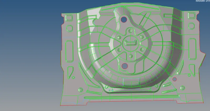
After the mid-surface is extracted, then we need to proceed to clean the midsurface for anywhere we might get a minimum length error. To do this, we firstly need to measure the distance between two points on the surface where we might get an element which might fail for minimum length.
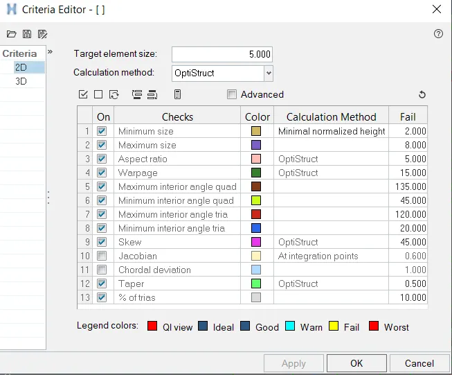
3. Before we can strat meshing, we need to set the Quality criteria for the meshing process. To do this, we need to use the Preferences tab and use the option of Criteria File Setting. In this option, we need to fill in all the necessary Quality criteria values such as the value of minimum and maximum length or and even the value for warpage etc.
4. After the Quality criteria is set, we then need to proceed to mesh the midusrface.

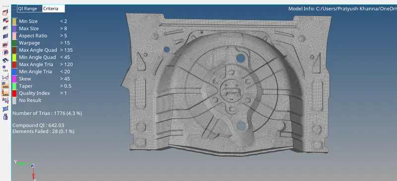
After meshing the entire mid surface, the mid-surface should look something like the following:
5. After the Meshing is done, the next step is to check for elements that have failed the Quality criteria set earlier. To check this, we need to see at two different places, the first one being in the 2D tab under the command of Quality check. Here we can see all the elements that are failing for any Quality criteria such as the minimum length or even the aspect ratio.
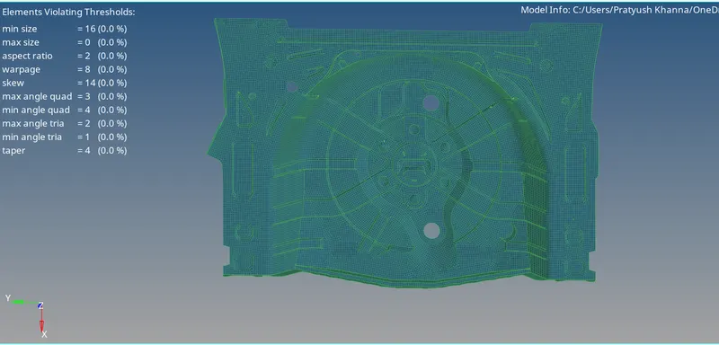
Final model after assigning the thickness-