Project - 2 - Meshing on the suspension Assembly
PROJECT 2:- MESHING ON THE SUSPENSION ASSEMBLY.
AIM:- To mesh the suspension assembly with the given quality criteria and appropriate connections where required.
PROCEDURE:-
1. Importing geometry files & check geometrical errors.
2. Midsurface generation for components having a thickness less than 5.0 mm.
3. Meshing the surface & defining volume for components having thickness more than 5.0 mm.
4. Giving connections for different locations.
5. Performing symmetry operation.
QUALITY CRITERIA:-
Quality Criteria for Surface Meshing of Tyre and Rim (Element type: Tria) :
|
S.No |
Quality Criteria |
Value |
|
1 |
Target/Average length |
6.5 |
|
2 |
Minimum Length |
5 |
|
3 |
Maximum Length |
10 |
|
4 |
Skewness |
45 |
Quality criteria for Surface Meshing of Non Uniform thickness components other than Tyre and Rim (Element type: Tria) :
|
S.No |
Quality Criteria |
Value |
|
1 |
Target/Average length |
4 |
|
2 |
Minimum Length |
2 |
|
3 |
Maximum Length |
6 |
|
4 |
Skewness |
45 |
Quality Criteria for Volume meshing of all Non Uniform thickness components (Element type: Tetra Elements):
|
S.No |
Quality Criteria |
Value |
|
1 |
Tet-collapse |
0.2 |
Quality criteria for Mid surfacing of Uniform thickness part which has thickness less than 5 mm (Element type: Mixed elements) :
|
S.No |
Quality Criteria |
Value |
|
1 |
Target/Average length |
4 |
|
2 |
Minimum Length |
2 |
|
3 |
Maximum Length |
6 |
|
4 |
Aspect |
3 |
|
5 |
Warpage |
15 |
|
6 |
Skewness |
45 |
|
7 |
Jacobian |
0.7 |
|
8 |
Minimum Quad Angle |
45 |
|
9 |
Maximum Quad Angle |
135 |
|
10 |
Minimum Tria Angle |
30 |
|
11 |
Maximum Tria Angle |
120 |
Geometry import & error check-
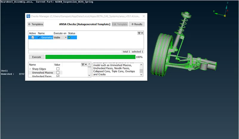
Once the cad modal is imported to ANSA, the modal is checked for geometrical errors like, triple cons, needle faces etc.
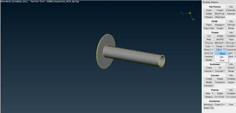
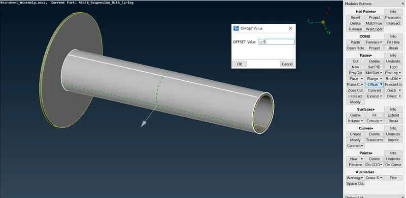
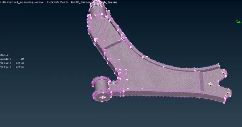
Extracting midsurface for components having thickness less than 5.0 mm-
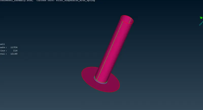
Once the midsurface is generated, the component is meshed with given quality criteria-
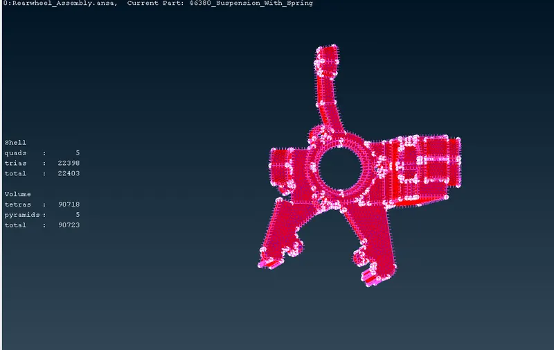
Meshing the component having thickness more than 5.0 mm-
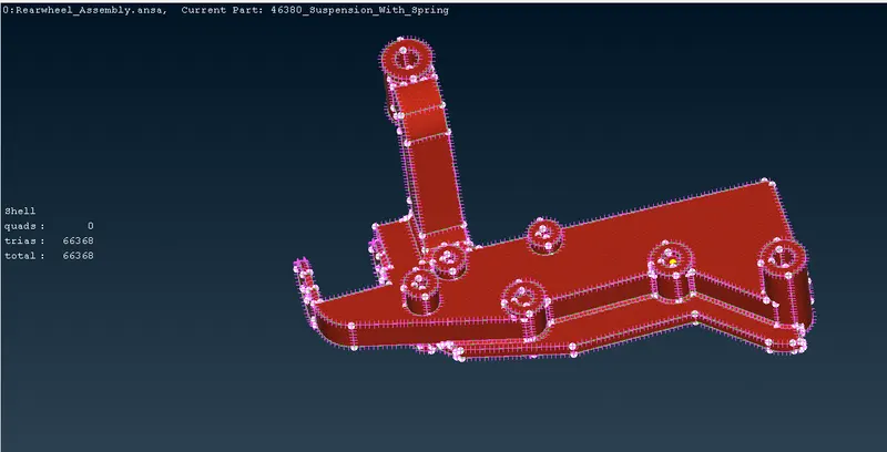
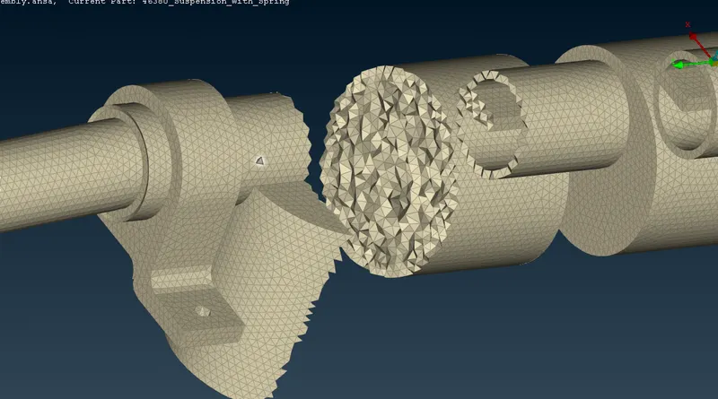
DEFINING VOLUME & GENERATING TETRA MESH
Once the component has meshed, volume is defined & solid mesh is generated using tetra rapid or tetra FEM.
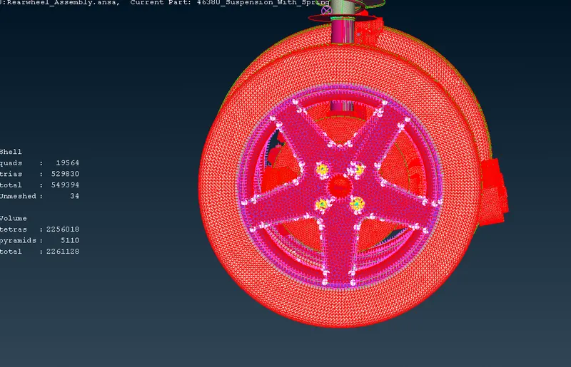
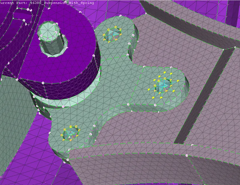
GIVING APPROPRIATE CONNECTIONS-
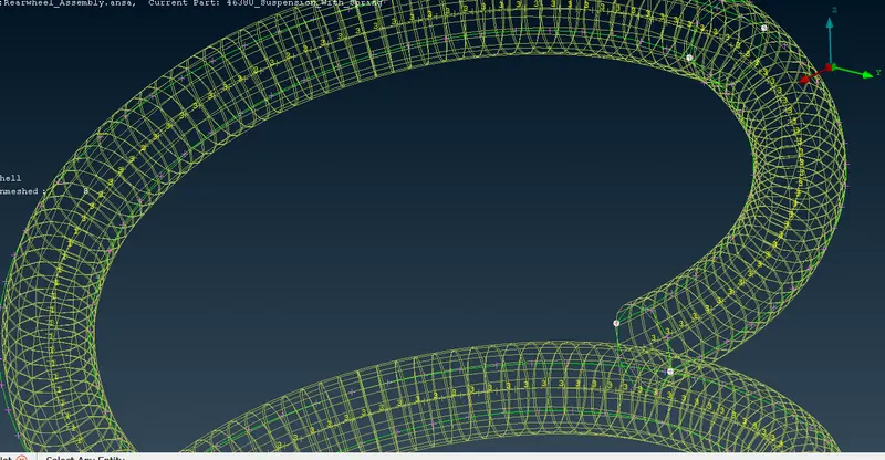
Nastran deck is used for defining the connections like RBE2 & seam weld & representing spring with 1D bar element.
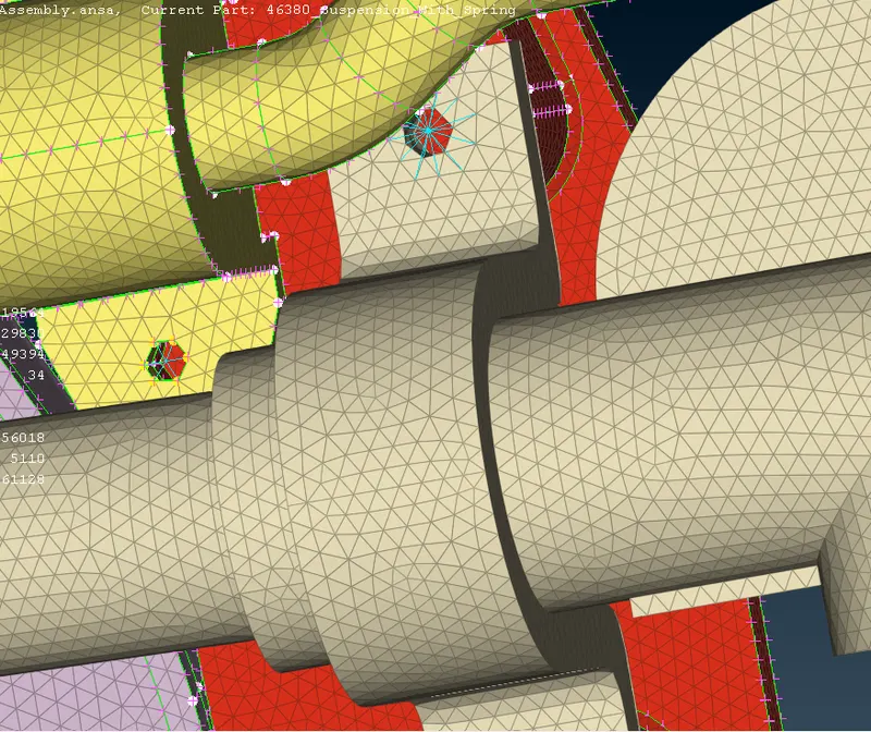
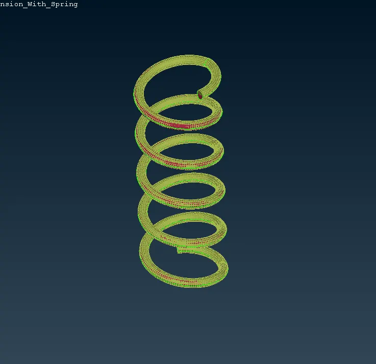
To represent a spring with 1d bar element , a curve is created in the center & COG is defined for the orientation.
In the Nastran deck, CBAR option is used , element length & PID is created.
By defining the radius, the area is calculated by ansa itself.Then clicking on OK, 1d element will be created.
SYMMETRY OPERATION-
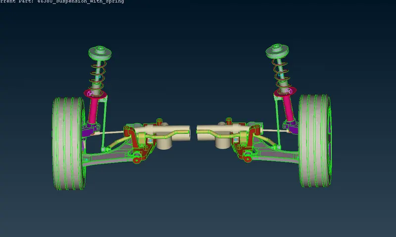
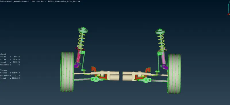
To create symmetry operation, transform option is used.
Select-Transform-Copy-Entities-Symmetry- mirror 3 points plane & select 3 points on entities & then click OK.
LEARNING OUTCOMES-
1. Gain experience in Mid surface extraction & meshing.
2. Able to do Batch meshing & generate solid mesh using Tetra rapid & tetra fem.
3. Concept of tet collapse.
4. Able to represent 1D element.
CONCLUSION-
Meshed suspension system by using 2d & tetra element alongwith generating solid mesh with quality criteria.