MESHING OF REAR WHEEL HOLDER IN HYPERMESH
I. OBJECTIVES
- To generate a Midsurface and perform geometry clean-up on the given component.
- To generate mesh on the given component with low tria concentration and proper mesh flow.
- To ensure that the mesh passes all the given Quality criteria.
- To assign various thickness components to the model.
II. GIVEN MODEL
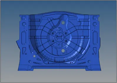 |
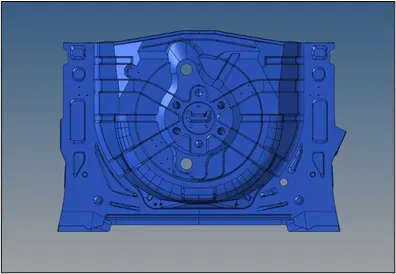 |
| Fig.1 Model Images |
III. FE PARAMETERS
- Target Element Length = 5 Units
-
S.N Quality Criteria Value 1 Aspect Ratio 5 2 Skewness 45 3 Warping 15 4 Taper 0.5 5 Min. Length 2 Units 6 Max. Length 8 Units 7 Min angle Quad 45 8 Max angle Quad 135 9 Min angle Tria 20 10 Max angle Tria 120 10 Tria % 10
IV. PROCEDURE
- Parent Surface Geometry Cleanup: -
- The given geometry is imported into the HyperMesh window. The view is set to By Topo which highlights all the edges on the geometry.
- We can instantly observe that there are some edges that are free and have to be corrected (except the large edges at the bottom) before extracting the midsurface. These are corrected by navigating to Geom → Quick edit and using the required commands like Toggle and Filler surface.
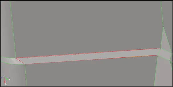
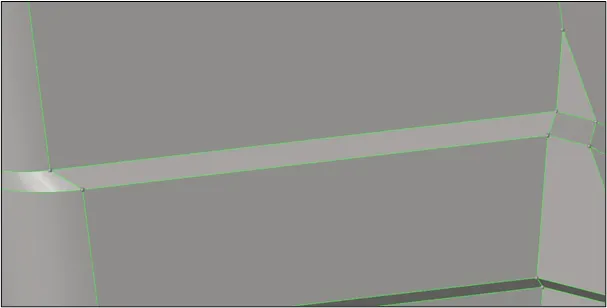
Fig. 2 Simple Parent Geometry Cleanup - Also, we shall correct any crooked lines or surfaces before extracting any midsurface which might affect the latter. We again use the Quick Edit panel for this function.
- An important step is to delete all the duplicates that might exist on the parent geometry. If not removed, these may cause further errors during midsurface extraction. For this, we will go to Geom → Defeature → Duplicate → Select all surfaces keeping default tolerance → Find → Delete. This removes all the unnecessary duplicates.
- There are surfaces on the geometry which are present in different components as seen in the model tree. We shall move them all in one single component. We use the Organise option in the Tools tab to move all surfaces. Once they are moved, the rest of the components are deleted.
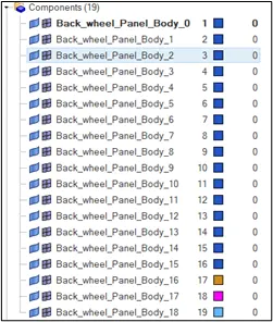
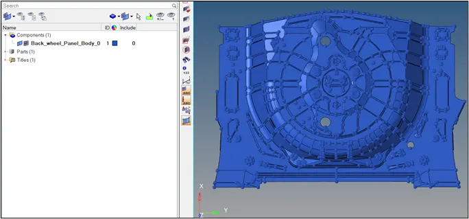
Fig. 3 Surfaces to one component
B. MidSurface Extraction and Geometry Cleanup: -
- After a basic parent geometry cleanup, we can now move on to extract the midsurface of the parent geometry. Since the parent geometry is consists of surfaces with the same thickness all over, we can directly offset the surfaces manually using the surface edit panel.
- Firstly, we check the distance between any arbitrary surfaces and note the thickness. We use the Distance option in the Geom tab to carry out this operation. The surfaces are 0.75 mm thick. Hence the offset value will be kept as 0.375 mm.
- Once that is done, we can navigate to Geom → Surface Edit → Offset → Select all surfaces → Duplicate them to a new component → Add offset value as 0.375 mm → Reverse normal → Offset. This will create our midsurface.
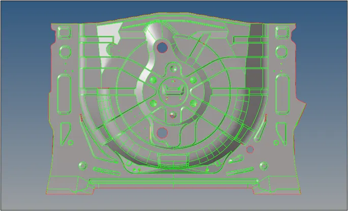
Fig.4 Midsurface Extraction - Once extracted, the midsurface shall be cleaned up. Geometry clean-up or Topology repair consists of correcting connectivity errors between adjacent surfaces. The errors include unconnected adjacent surfaces, duplicate surfaces, missing surfaces. The goal of topology clean-up is to restore the surface data to a perfectly clean representation of the part.
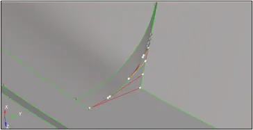
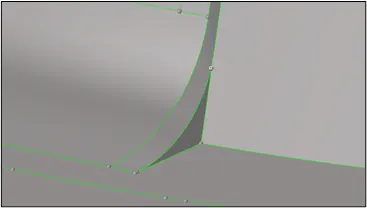
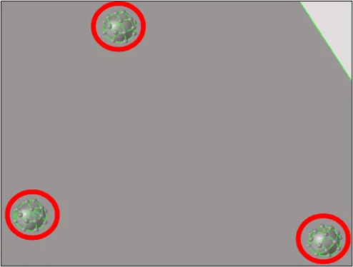
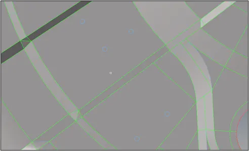
Fig.5 Topology Correction - For a few symmetrical surfaces, the cleanup is done on one side only. At the time of creating the mesh, it will be reflected on the other side.
- Finally, the whole surface domain has to be divided into simpler shapes of squares or rectangles, so that we get a good mesh flow with minimum amount of trias. For this we got to Geom → Quick edit and use the Node to Node or Node to Line to trim surfaces. This done on all surfaces except one side of the symmetry.
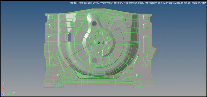
Fig.6 Final Geometry Cleanup
C. Mesh Generation and Quality Cleanup: -
- The first step is to set the required mesh criteria. So we navigate to Preferences → Criteria File Settings and then the following values are input.
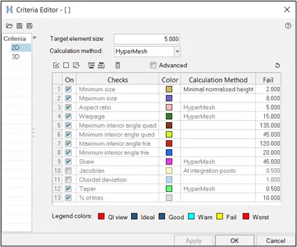
Fig.7 Mesh Quality Criteria - Now we can start meshing the surfaces, beginning from any arbitrary surface but the mesh should move inside in an outward direction. We will use the Automesh feature in the 2D panel. We have to ensure that the selector is set to surfaces. The element size is set to 5 mm and type to mixed.
- Now the most demanding task is to create meshes on a set of similar adjacent surfaces one by one. This is done so that we can make changes to the mesh densities according to our desired mesh flow. Once the mesh is created, the mesh density is toggled to get the desired flow without tria elements. This way a mesh with good flow is generated over the whole model. The elements are remeshed wherever necessary to get a low tria concentration.
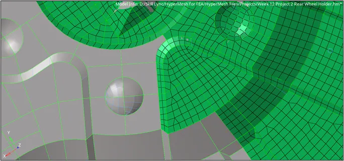
Fig.8 Mesh generation on adjacent surfaces - The meshes corresponding to symmetrical surfaces have to be reflected to the remaining surfaces. This is done by navigating to Tools → Reflect → Select the respective elements → Duplicate them to the current comp → Select the base point → Toggle to the correct axis → Reflect.
- Once reflected, the elements have to be joined together since they lack connectivity after mirroring. Hence, the Edges command is used to carry out this procedure. We go to Tools → Edges → Toggle to elements → Select all elements → Find edges. Once edges are highlighted by red line, the respective elements are selected and then Equivalence option is clicked. This will stitch the elements together.
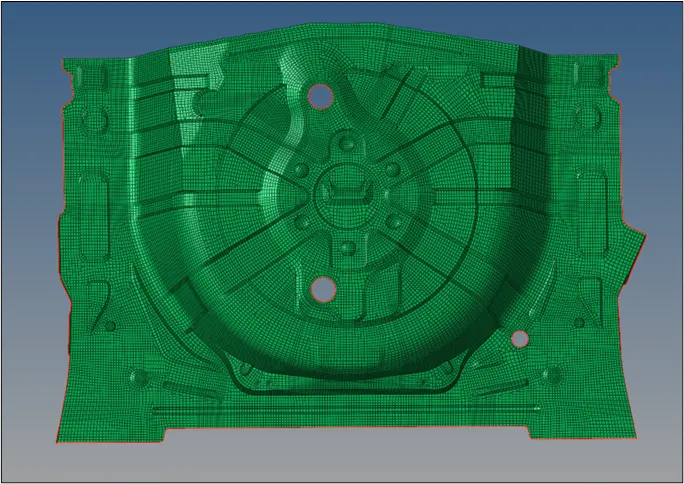
Fig.9 Element Edges removed - After creating the mesh, we have to rectify the failing elements. To view the element quality, we use the quality index menu in the 2D panel and check which elements are failing. Once tracked, we try to rectify all those elements that are failing using the element optimize, drag tria, place node, and split quad options in the same menu. It is thoroughly ensured that all the elements pass the criteria.
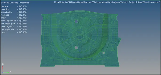
Fig.10 Resultant elements after cleanup
D. Creating Property and Assigning the Thickness: -
- To create a property, we will right-click on the model tree, select create and add a Property. We will rename the card according to the thickness values. Scrolling down the card edit window, we will find Thickness and add the concerned thickness value. Also, we can change the color card.
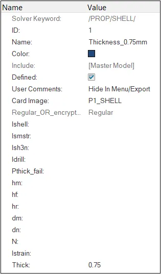
Fig.11 Adding Thickness Property - Now all the midsurface component is assigned with the aforementioned property. This can be done by right-clicking on the respective component and then clicking Assign. Now the property with corresponding thickness is selected and then apply is selected. With this step, we have come to an end of the procedure.
V. FINAL MODEL
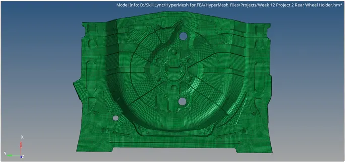
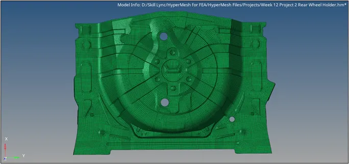
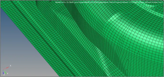
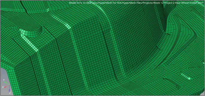
| Fig.12 Final Model Images |
VI. CONCLUSIONS
- The following conclusions were drawn from this challenge:-
- The manual midsurface extraction of the surfaces was successfully conducted.
- The geometry cleanup of the midsurfaces was done according to our desired mesh flow.
- The mesh model was able to fulfill all the mesh quality parameters with just 3.1% Tria concentration.
- The thickness property was assigned to the respective surfaces.