MESHING OF DOOR INNER PANEL IN HYPERMESH
I. OBJECTIVES
- To generate a Midsurface and perform geometry clean-up on the given component.
- To generate mesh on the given component with low tria concentration and proper mesh flow.
- To ensure that the mesh passes all the given Quality criteria.
- To assign various thickness components to the model.
II. GIVEN MODEL
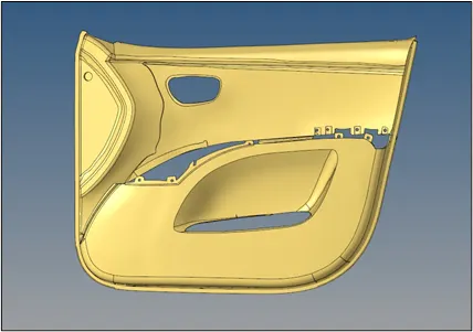 |
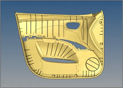 |
| Fig.1 Model Images |
III. FE PARAMETERS
- Target Element Length = 4 Units
-
S.N Quality Criteria Value 1 Aspect Ratio 5 2 Skewness 45 3 Warping 15 4 Taper 0.5 5 Min. Length 2 Units 6 Max. Length 6 Units 7 Min angle Quad 45 8 Max angle Quad 135 9 Min angle Tria 20 10 Max angle Tria 120 10 Tria % 10
IV. PROCEDURE
- Parent Surface Geometry Cleanup: -
- The given geometry is imported into the HyperMesh window. The view is set to By Topo which highlights all the edges on the geometry.
- We can instantly observe that there are some edges that are free and have to be corrected (except the large edges at the bottom) before extracting the midsurface. These are corrected by navigating to Geom → Quick edit and using the required commands like Toggle and Filler surface.
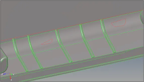
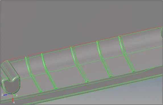
Fig. 2 Simple Parent Geometry Cleanup - Also, we shall correct any crooked lines or surfaces before extracting any midsurface which might affect the latter. We again use the Quick Edit panel for this function.
- An important step is to defeature all the small surface fillets which are below the required dimensions. A majority of these are on the Surface Ribs. To remove them, we use Geom → Defeature → Surf Fillets and select all the mandatory surfaces with the fillets. We set the minimum and maximum radius as 0.1 and 10 and click on Find. All the highlighted fillets are removed by clicking the Remove button. If at all some fillets are not removed, then those are reselected and removed again.
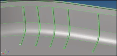
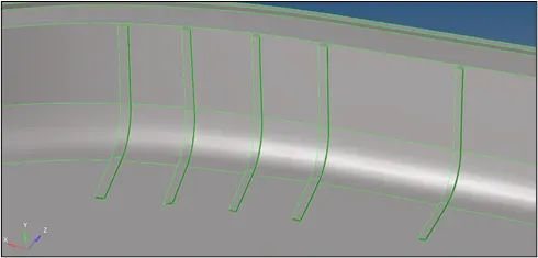
Fig.3 Defeaturing of Fillets
B. MidSurface Extraction and Geometry Cleanup: -
- After a basic parent geometry cleanup, we can now move on to extract the midsurface of the parent geometry. Since the parent geometry is highly complex and consists of surfaces with variable thicknesses. Hence, a stepwise procedure has to be followed to extract a complete midsurface off the parent geometry.
- Firstly, we check the distance between any arbitrary parallel surfaces and note them according to their positions. We use the Distance option in the Geom tab to carry out this operation. For example, the outermost trim surrounding the geometry is 2 mm thick whereas the vast majority of surfaces within are 2.8 mm thick.
- Once that is done, we can distinguish which surface has to be extracted at what mid-dimension. Since the main inner surfaces are large, we can go to Geom → Midsurface → Extraction Options → Select Skin Offset → Auto extraction, and select any surface. By default, the program will select all the attached surfaces. Once we click Extract, after some time a Middle surface of the inner geometry and a satisfactory surface is extracted. as seen in the figure.
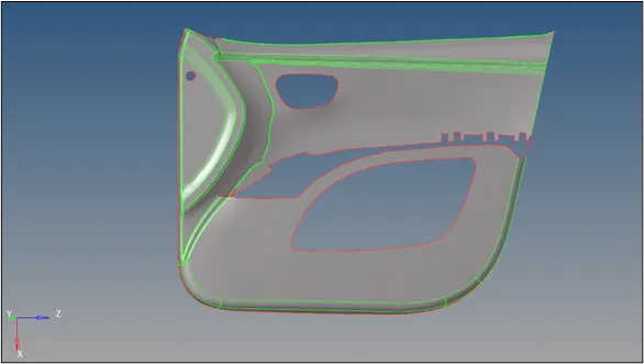
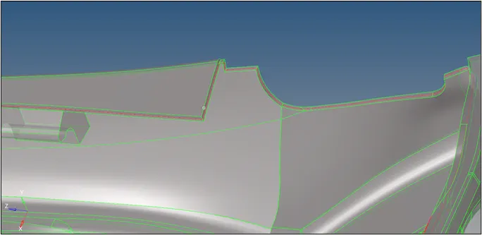
Fig.4 Midsurface of Inner Surfaces - As it is evident that the auto midsurface fails to extract those midsurfaces which lack connectivity after the extraction process. Thus, in this case, we have to extract the rest of the surfaces and the ribs manually. This can be done by navigating to Geom → Surface edit → Offset and then selecting the required surfaces, like the outer trim, and then duplicating those surfaces to the Middle surface component. We put an offset value of half the thickness and click on vector normal to see the direction of the offset. The normals are reversed if the offset direction is opposite to what we need. The Offset button is clicked and a middle surface is created. This is done with all the remaining surfaces as well.
- For the ribs, we can go to Geom → Midsurface → Final Edit tools → Surface pair → Select the two parallel sides of the ribs → Extract to the current component. This gives midsurfaces of the ribs on the middle surface component. This is done for all the ribs and parts.
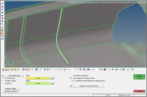
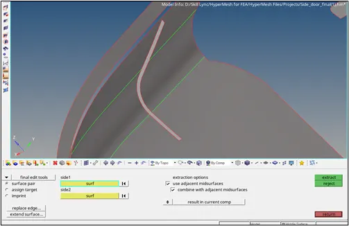
Fig.5 Rib Midsurface - Now the extracted midsurfaces will have no contact with the originally extracted inner midsurface. To provide contact, we will have to extend the ribs' midsurfaces to the inner mid surface. This can be done by navigating to Geom → Surface edit → Extend → Toggle to Extend over edges and change the cross extension to the Surfs: to target option. The underside lines of the ribs are selected and the target surfaces are selected. Once clicking on extend, the ribs extend to those surfaces marked by a yellow T-connection.
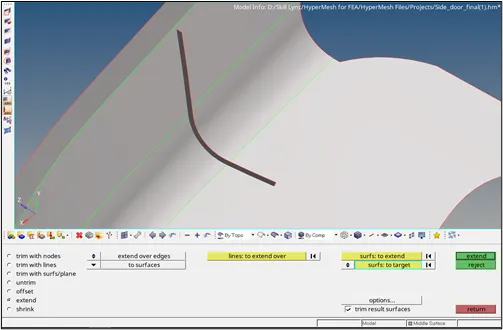
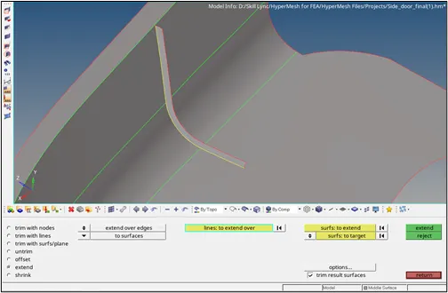
Fig.6 Rib Extension - There are some holder components that cannot be modeled in 2D. Hence we will convert those components as follows using Geom → Surfaces.
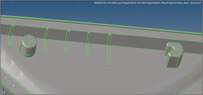
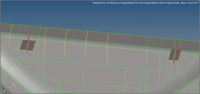
Fig.7 Holder Component Modeling - There are several ribs and parts that have thicknesses as seen in the parent geometry. We will measure the thicknesses of all of them and move the parts with respective thicknesses into other components. The thickness is measured using the Geom → Length or Distance. New components are created by right-clicking on the model tree and selected create → Component. The names of the new components are kept according to their thicknesses to avoid confusion. To move, we go to Tools → Organise → Select Surfs Option and then select the concerned midsurfaces. Then the move button is clicked.
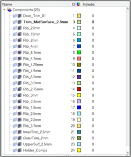
Fig.8 Parts assigned with separate Components
- Once all the extensions and 2D midsurfaces are separated via components, we move on to carry out the geometric cleanup of the final midsurface. For this, we use the Quick edit option in the Geom panel. Figure 9 shows the final midsurface after the cleanup.
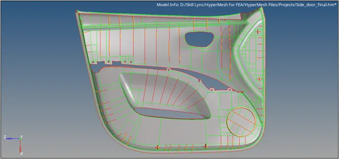
Fig.9 Geometry Cleanup of the Midsurface
C. Mesh Generation and Quality Cleanup: -
- The first step is to set the required mesh criteria. So we navigate to Preferences → Criteria File Settings and then the following values are input.
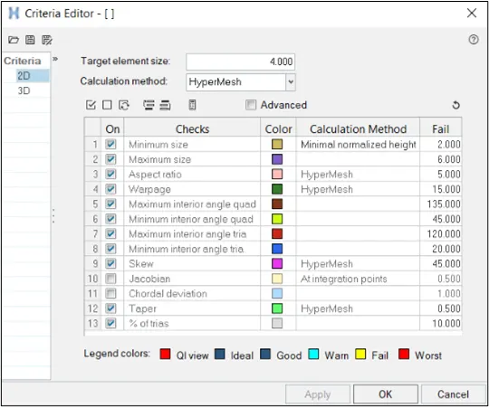
Fig.10 Mesh Quality Criteria
- Now we can start meshing the surfaces, beginning from any arbitrary surface but the mesh should move inside in an outward direction. We will use the Automesh feature in the 2D panel. We have to ensure that the selector is set to surfaces. The element size is set to 4 mm and type to mixed.
- Now the most demanding task is to create meshes on a set of similar adjacent surfaces one by one. This is done so that we can make changes to the mesh densities according to our desired mesh flow. Once the mesh is created, the mesh density is toggled to get the desired flow without tria elements. This way a mesh with good flow is generated over the whole model. The elements are remeshed wherever necessary to get a low tria concentration.
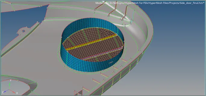
Fig.11 Mesh generation on adjacent surfaces
- After creating the mesh, we have to rectify the failing elements. To view the element quality, we use the quality index menu in the 2D panel and check which elements are failing. Once tracked, we try to rectify all those elements that are failing using the element optimize, drag tria, place node, and split quad options in the same menu. It is thoroughly ensured that all the elements pass the criteria.
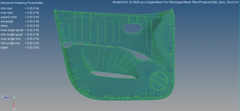
Fig.12 Resultant elements after cleanup
D. Creating Properties and Assigning Thicknesses: -
- To create a property, we will right-click on the model tree, select create and add a Property. We will rename the card according to the thickness values. Scrolling down the card edit window, we will find Thickness and add the concerned thickness value. Also, we can change the color card.
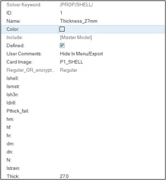
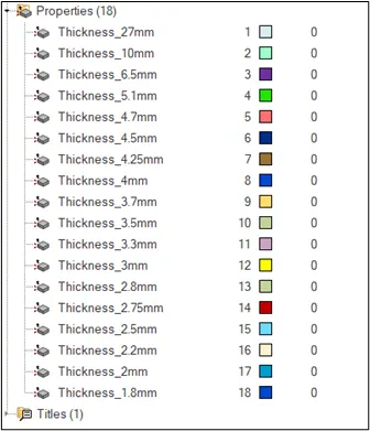
Fig.13 Adding Thickness Property - Now all the components are assigned with the aforementioned properties. This can be done by right-clicking on the respective component and then clicking Assign. Now the property with corresponding thickness is selected and then apply is selected. This is done for all the components. With this step, we have come to an end of the procedure.
V. FINAL MODEL
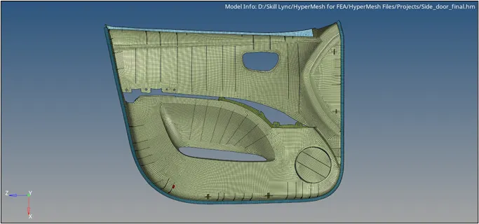
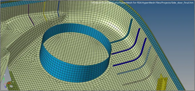
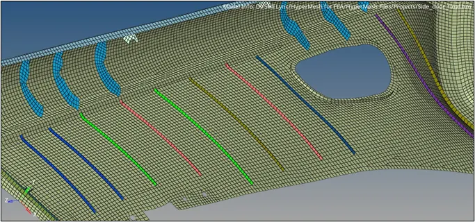
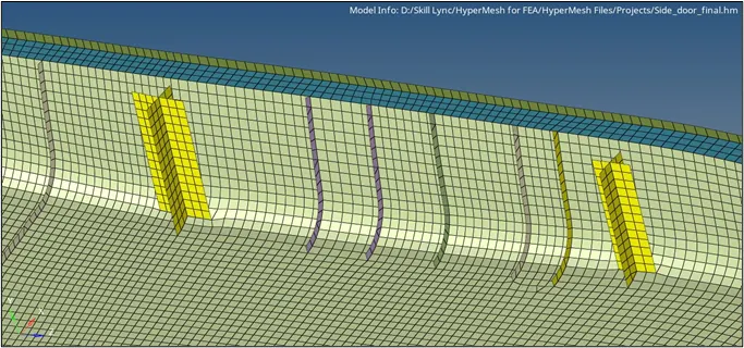
| Fig.14 Final Model Images |
VI. CONCLUSIONS
- The following conclusions were drawn from this challenge:-
- The manual midsurface extraction of the surfaces was successfully conducted.
- The geometry cleanup of the midsurfaces was done according to our desired mesh flow.
- The mesh model was able to fulfill all the mesh quality parameters.
- The thickness properties were assigned to the respective surfaces.