Project 1 - 2D meshing on the instrumental Panel
I. OBJECTIVES
- To perform Geometry Clean-up of the surfaces of the given component.
- To extract the Midsurface from the component of the given model.
- To generate mesh on the given component with low tria concentration and proper mesh flow.
- To ensure that the model passes all the given mesh quality parameters apart from the triple surface regions.
- To assign thickness to the midsurface coinciding with the parent geometry.
II. CAD MODEL - HOOD ASSEMBLY
 |
|
Fig.1. The CAD Image of inner Panel Substrate |
III. PARAMETERS
-
S.No
Quality Criteria
Value
1
Target/Average length
4
2
Minimum Length
2
3
Maximum Length
6
4
Aspect
3
5
Warpage
15
6
Skewness
45
7
Jacobian
0.7
8
Minimum Quad Angle
45
9
Maximum Quad Angle
135
10
Minimum Tria Angle
30
11
Maximum Tria Angle
120
12
Tria Percentage
15
IV. PROCEDURE
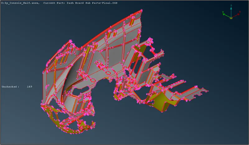
- The given CAD model is imported in the ANSA window as a .ansa file as seen in Fig 1.
- Also, all the edges on the model are evidently free and require stitching to get yellow double cons. The Topo option from the Faces menu is used to do so.
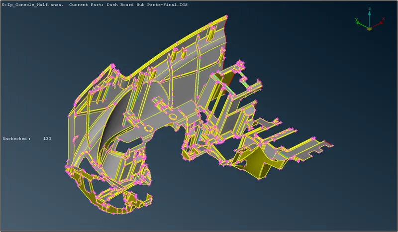
Fig.2. Checks Manager window
- Extraction of the Mid Surface, Ribs, and Geometry Cleanup:-
- Before extracting the midsurface from the parent geometry, we will have to remove all the discrepancies from the model like needle faces, overlapping faces, free edges, triple and single cons, etc. To do this we navigate to Tools → Checks → Geometry. The Execute button is clicked and all the issues are displayed in red. Since the auto-fix is possible, all the issues are selected, and by hitting right-click, we select fix. All the visible issues shall be fixed.
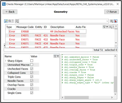
Fig.3. Checks Manager window - Moving to midsurface extraction, there are two ways to do so. One is automatic and the other is manual. For this model, we will use the manual midsurface option since it is complex geometry and the algorithm might not be able to create a good surface. For surfaces like the top part of the model, where the middle option cannot be used, the offset option is used to get the mid surface. The thickness of the surface is first measured. Then we navigate to Topo → Faces → Offset and select the face to offset. The offset value is input as half of the distance measured i.e. 0.6 mm. The offset surface will be created.
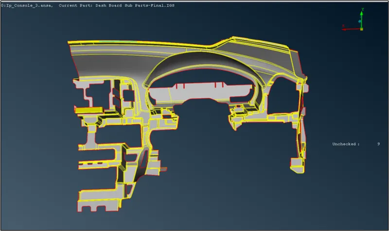
Fig.4. Extracted midsurfaces - For the ribs, we can go to Topo → Faces → Middle → Select the two parallel sides of the ribs and select a new PID for the rib. This gives midsurfaces of the ribs on the middle surface component. This is done for all the ribs and parts.
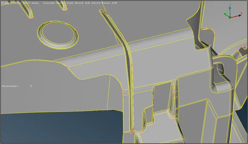
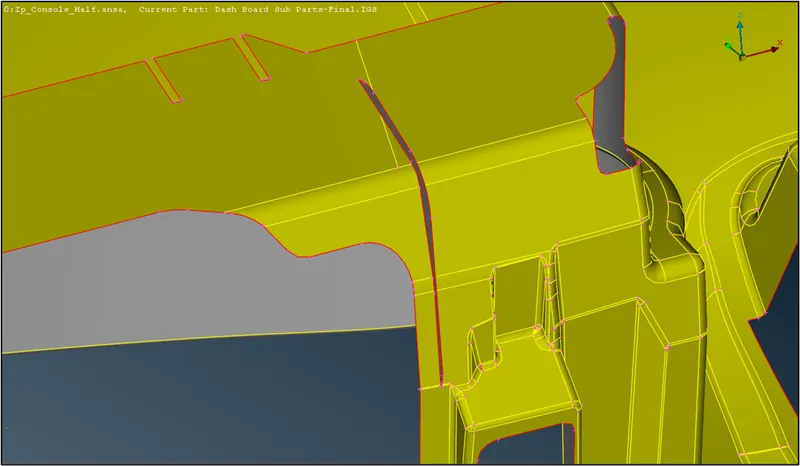
Fig.5. Rib Midsurface - Next, the extracted rib midsurfaces have to be extended to the parent midsurface. We can navigate to Topo → Faces → Extend → Select the edges to extend and middle-click to select the surface to extend. This will stretch the rib to create a triple con with the parent midsurface.
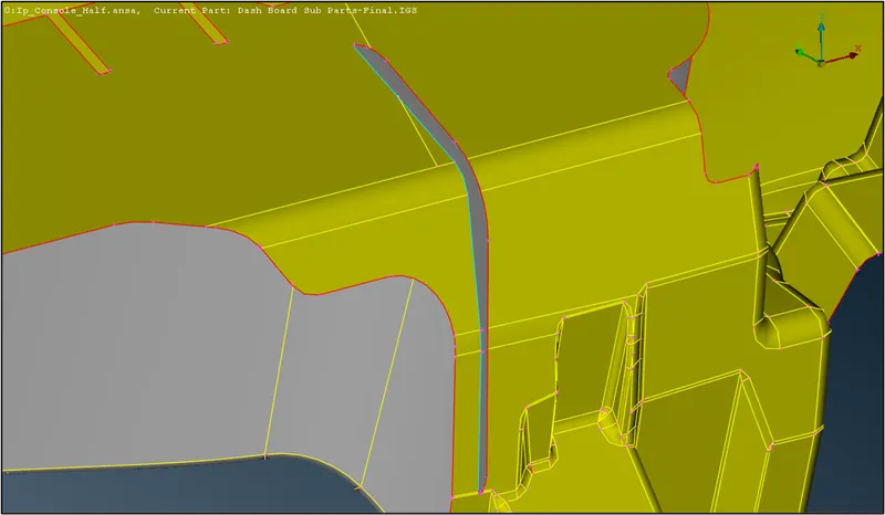
Fig.6. Extension of the Rib midsurface - All ribs with respective thicknesses are transferred to the different PIDs which have various thickness values added.
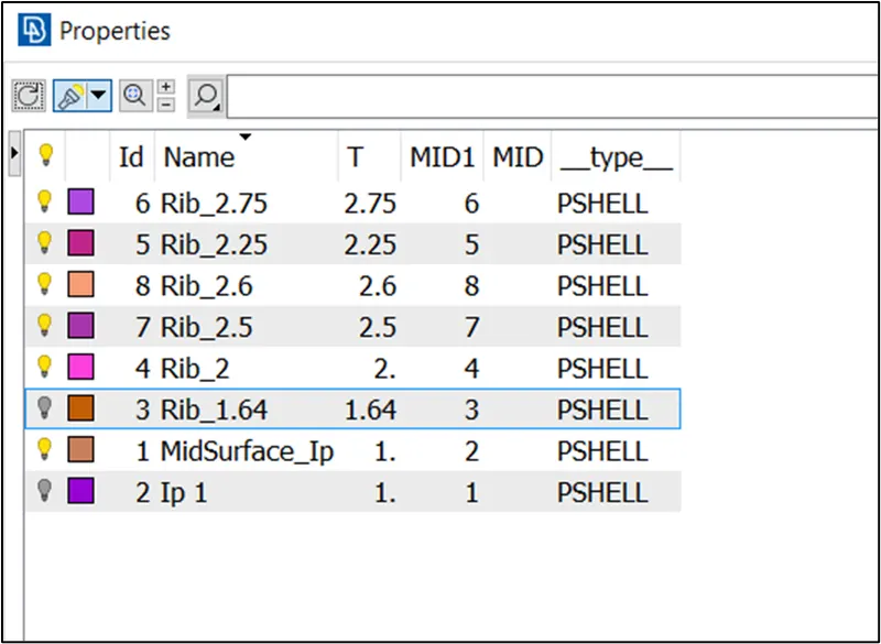
Fig.7. Properties Window - There are some doghouse components that cannot be modeled in 2D. Hence we will convert those components into a cross pattern as follows using the 3D curves option. 3D curves are used to map the outline of the doghouse from the parent geometry and create surfaces out of them as midsurfaces. Once the surfaces are created, they are extended to the parent midsurface similar to the previous step. Also, some of these ribs pass through each other without intersection. The intersect tool is used for this purpose soo as to get an intersecting edge.
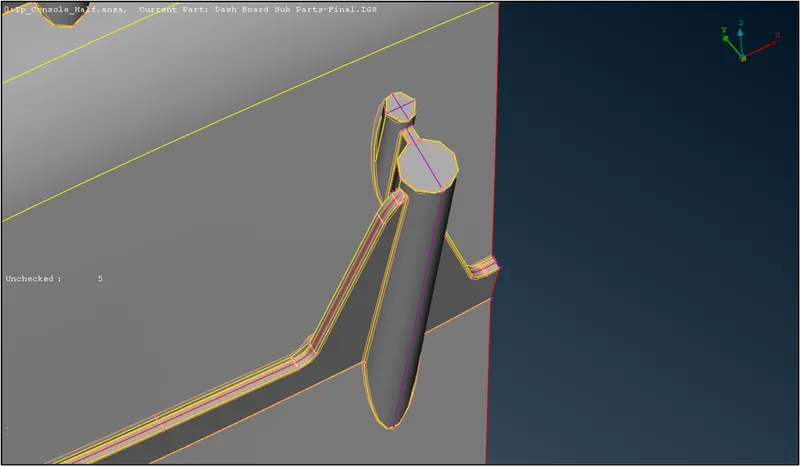
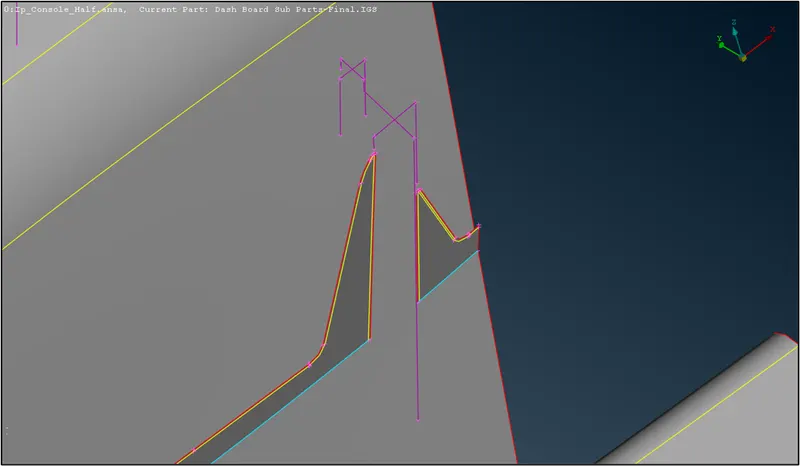

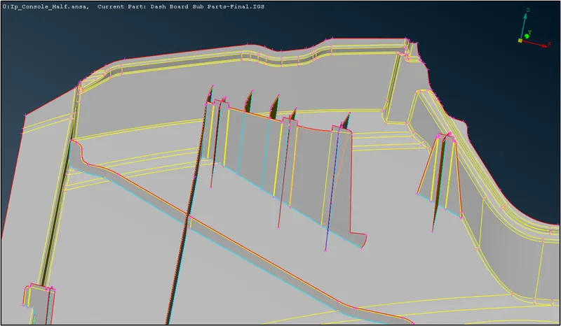

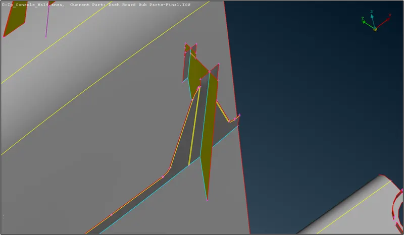
Fig.8. Cross pattern surfaces for Doghouses - Now, the midsurface geometry is scanned manually for any impending discrepancies like free edges. Any such discrepancy is rectified by deleting that area and creating a new one.
B. Mesh Generation and Quality Check:-
- Before generating the mesh on the midsurfaces, we have to feed the mesh criteria to the algorithm so that we get the desired quality. For this, we click the Quality Criteria and input the required criteria. The Mesh Parameter is also changed where we set the average element length as 4 and the min and max length is set to 2 and 6 respectively.
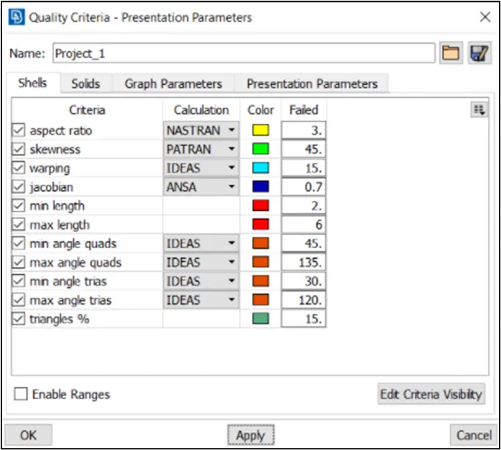
Fig.9. Mesh Quality Criteria - To get a proper mesh flow, we have to start the mesh generation from the inside and move outwards. Also, the macros should be divided into parts so that the algorithm can generate a mesh with a good flow. To do this we use the Cut option for Macros in the Mesh tab. Unwanted lines are removed and required zones are made.
- First, the perimeter number is set as desired and the Best mesh option is selected to create the mesh. If the mesh flow is not as required, the reconstruct option is used to try another algorithm to mesh that macro. To get the best mesh to flow possible, we can also use the Refine option, but minimal usage of this tool is done because this creates a mesh by ignoring the mesh parameters.
- While meshing the components, we will encounter the tria elements which will be inevitable. But some trias like back-to-back and opposite trias have to be avoided at all costs. We use the split option to remove such elements. A very good article has been made on this. The tria element is split till it reaches the nearest opposing tria. Once that is done, the trias can be joined to form Quads and then the mesh can be smoothened out.
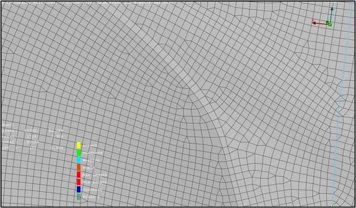
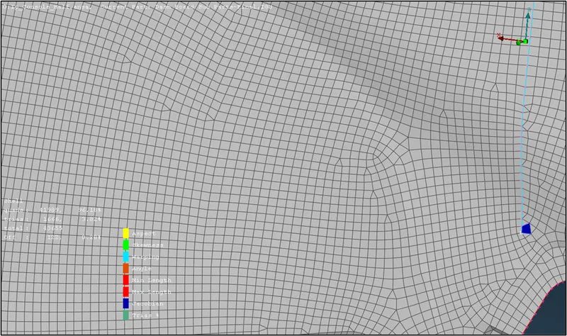
Fig.10. Reconstruction of mesh for better flow 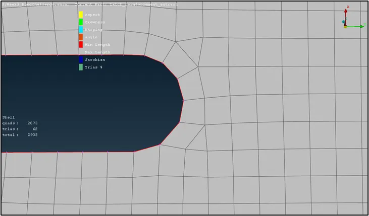
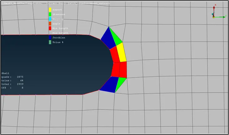
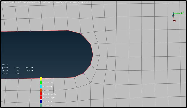

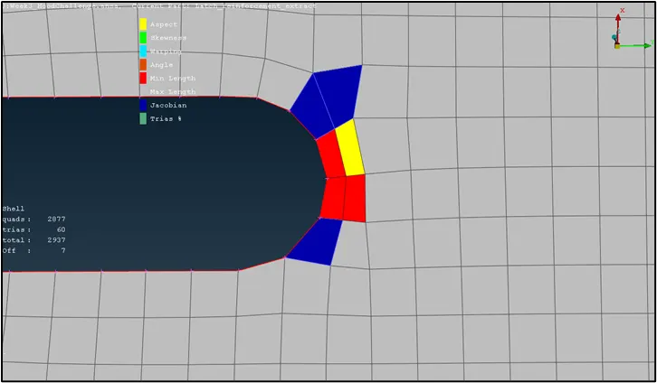
Fig.11. Tria Removal using Split option - Now it's a good practice to view the Quality of mesh while it is being created so that any discrepancy can be rectified easily before the whole part is meshed. Hence, the Hidden mode is switched on to see the failing elements. To rectify any failing elements, we have to play around with various options. In some cases, by using the Smooth option, the failing elements are rectified. But in other cases, we will have to make the mesh finer so that the major area is covered without abusing the criteria.
- Since the mesh is assigned with the respective properties of the midsurfaces, the thickness is also defined to the mesh. This can be viewed by switching the Draw shell as a solid option to On.
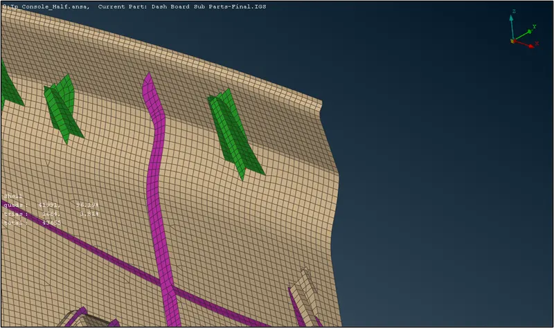
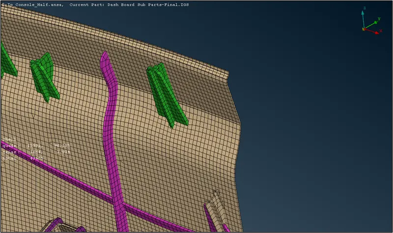
Fig.12. Mesh Thickness display
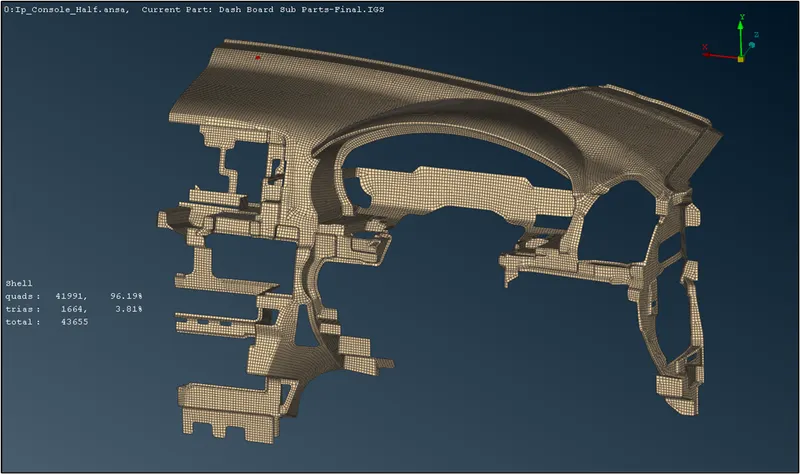
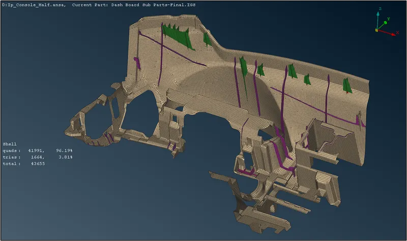
V. RESULTS - FINAL FE MODEL
 |
 |
VI. LEARNING OUTCOMES
- From the above assignment, the following points were learned in ANSA software:-
- Topological/Geometry clean-up
- Auto and manual midsurface extraction
- Mesh generation and mesh flow verification
- Mesh Quality and Parameters check
VII. CONCLUSIONS
- The FE modeling of the given Instrumental Panel substrate has been completed and the following points are drawn as conclusions: -
- The midsurfaces for the given model were successfully extracted.
- A manual Geometry Clean-up procedure was done on the extracted midsurfaces.
- The 2-D mesh was deployed on the components with a good mesh flow and low trias concentration.
- For feature capturing, the failing elements were ignored and are inevitable.
- The FE model was ensured to pass the mesh quality parameters according to the assignment.