Week 12:Project-1-Meshing of Door Inner Panel Challenge
OBJECTIVE : 1.To generate the mid -surface for the given Side-Door panel model
2.To Carry out the Geometric Clean up of the mid-surface
3.Generating mesh with low tria concentration & maintaining proper mesh flow
4.Maintaining the Quality criteria given below
Target Element Length = 4 Units
|
S.N |
Quality Criteria |
Value |
|
1 |
Aspect Ratio |
5 |
|
2 |
Skewness |
45 |
|
3 |
Warping |
15 |
|
4 |
Taper |
0.5 |
|
5 |
Min. Length |
2 Units |
|
6 |
Max. Length |
6 Units |
|
7 |
Min angle Quad |
45 |
|
8 |
Max angle Quad |
135 |
|
9 |
Min angle Tria |
20 |
|
10 |
Max angle Tria |
120 |
|
10 |
Tria % |
10 |
- Assigning Thickness to the component
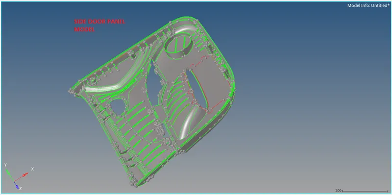
Fig 1 Cad model image of the Side Door Panel
PROCEDURE:
1.Importing the geometry :
The given step geometry is Imported through the import model option in the standard selection panel.
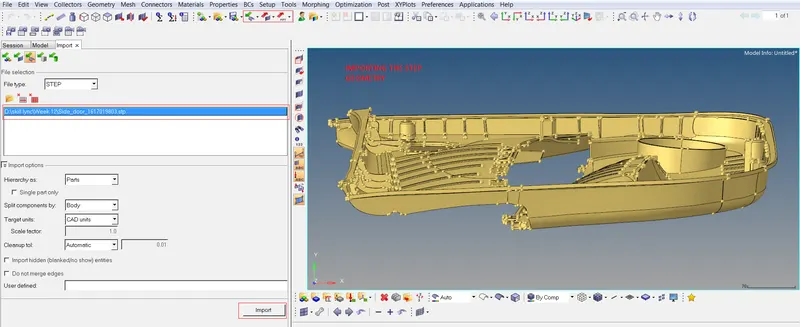
Fig 2 Importing the Step Geometry
2.Splitting the Side door panel into 4 Components :
The Model is split into 4 components through the trim with Surface/ plane in the Surface edit option(Shift + F9).
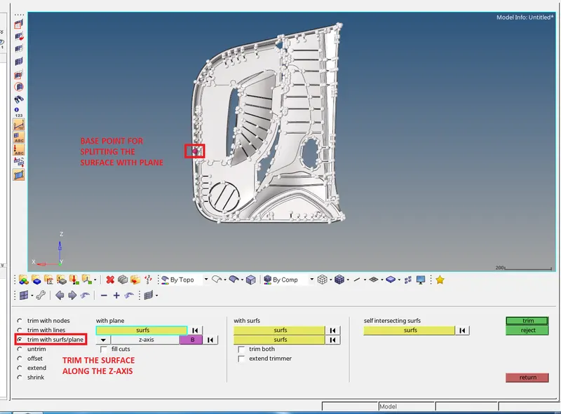
Fig 3 _Splitting the Model by trim with Surf-plane in the Surface edit panel
3.Moving the Split Surface to new components :
The Split Body is moved to the newly created components through the Organize tool.
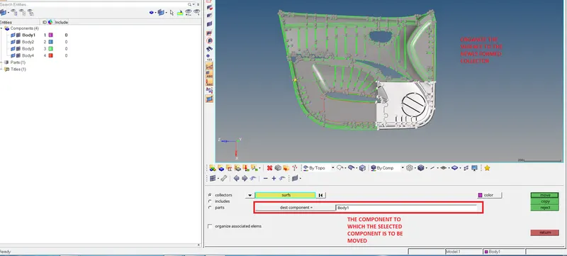
Fig 4 Moving the Split component to the new component through the organize tool
4.Creating the Mid Surface :
i) De-featuring the Fillets :
In the geometry module, the fillets are de featured through the de-feature option by selecting the surface fillets option , setting the minimum fillet radius and maximum fillet radius and selecting the fillets.
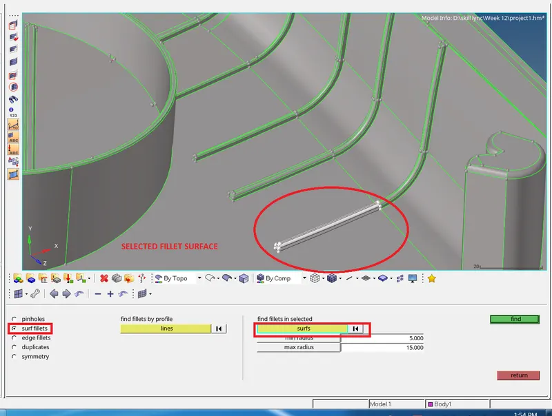
Fig 5 De-featuring the Fillet
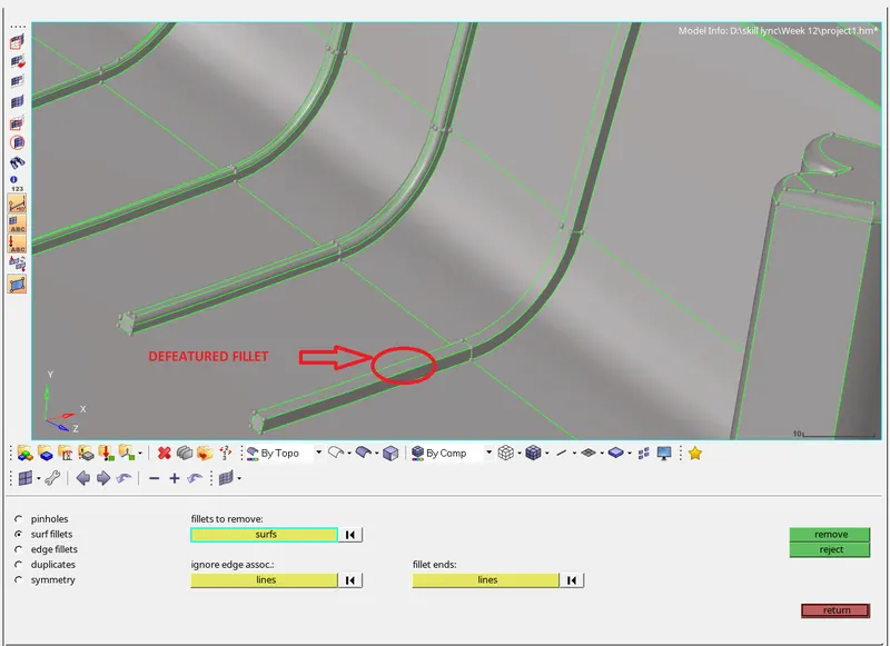
Fig 6 De-featured fillet
ii)Measuring the thickness of the Surface :
The Surface thickness should be measured using the measure command ( F4) .
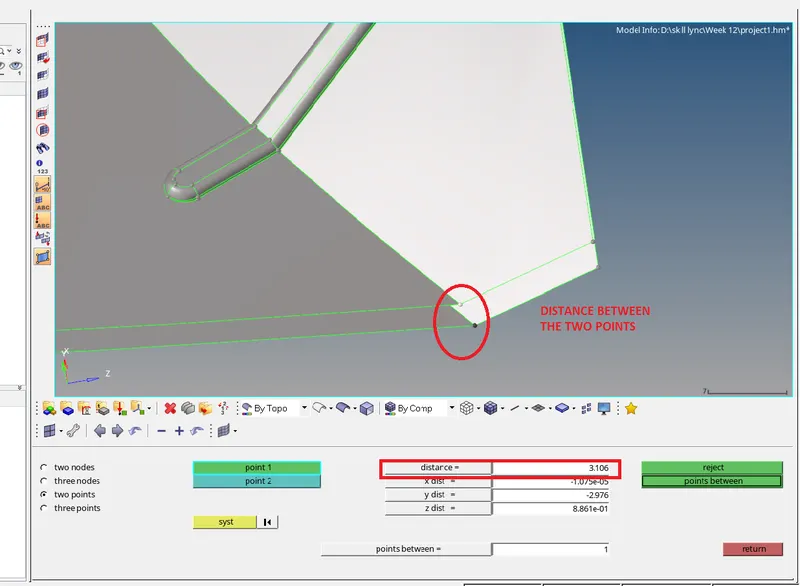
Fig 7 Measurement between two points
iii)Creating the Surface Offset :
Based on the surface thickness measured previously through the measure command the , the surface is offset by nearly half the measured thickness surface after having duplicated one side of the surface using the Offset option in the Surface edit option.
- The Surfaces which are to be offset are duplicated and then the normal to the surface is checked in order to check the direction in which the surface would be offset.
- If the direction in which the offset of the surface created is opposite to the desired direction then reverse normal button is hit & the duplicate surface is selected again & the offset is created .
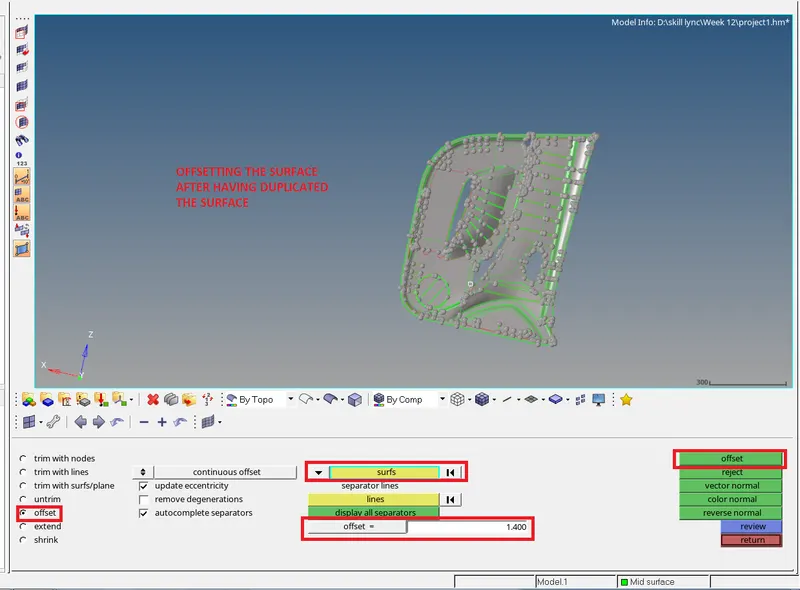
Fig 8 Off-setting the surface
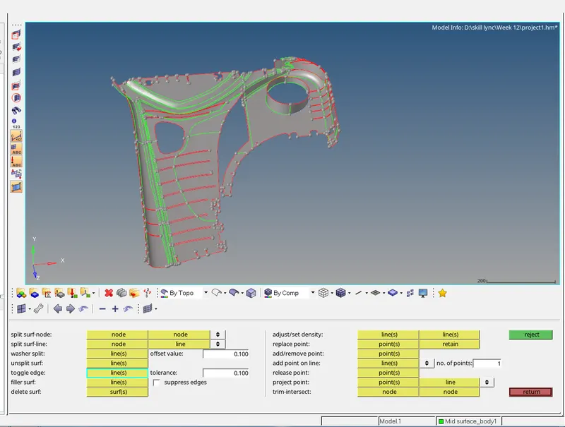
Fig 9 Manually extracted mid -surface
v) Geometric-Clean Up :
The Geometric Clean- up of the model needs to be carried out before Meshing using the various available tools.
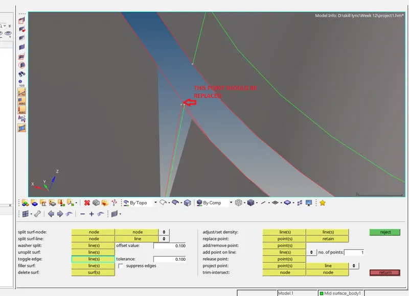
Fig 10 Before the Geometric clean-up of the manually extracted mid -surface
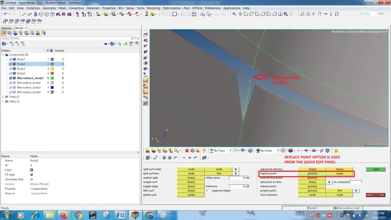
Fig 11 After the Geometric clean-up of the manually extracted mid -surface
5) Meshing :
The extracted mid-surface is meshed using the mesh option (F12) from the keyboard keeping the target element as 4mm.
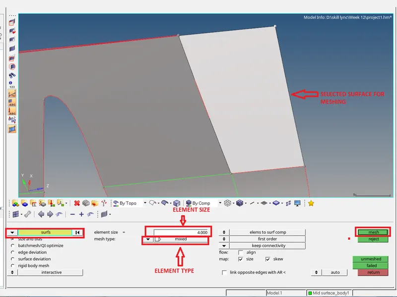
Fig 12 Meshing the mid-surface with element size of 4mm
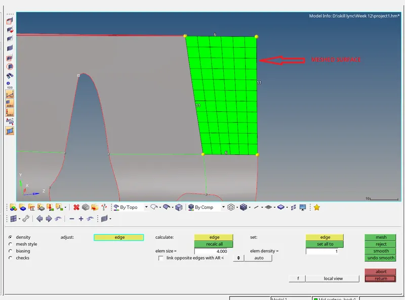
Fig 13 Meshed Surface
6) Ensuring Element Connectivity between the elements of adjacent Surfaces:
The Elements between two adjacent surfaces should have connectivity.
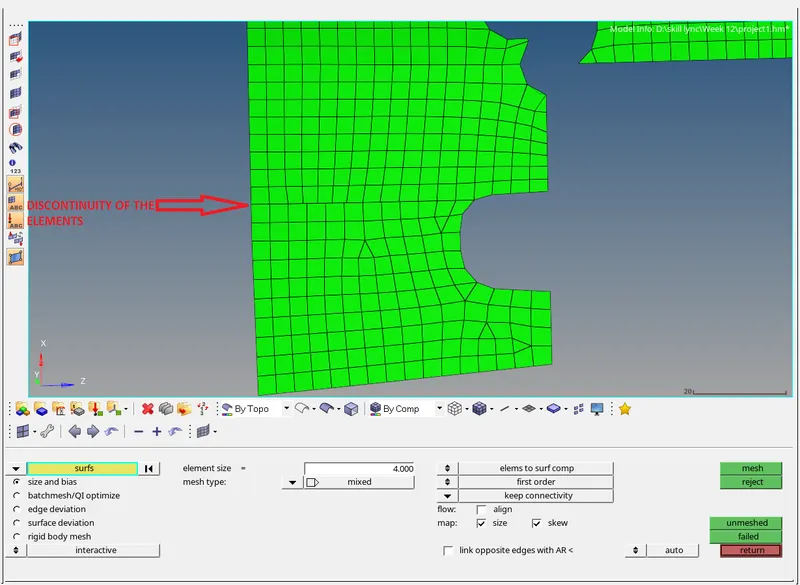
Fig 14 Discontinuity of the Elements
The disjointed elements are identified by Using edge tool from the tools panel. The Preview equivalence option in the Edge tool are used and Equivalence button is hit to create equivalence between the Discontinuous elements .
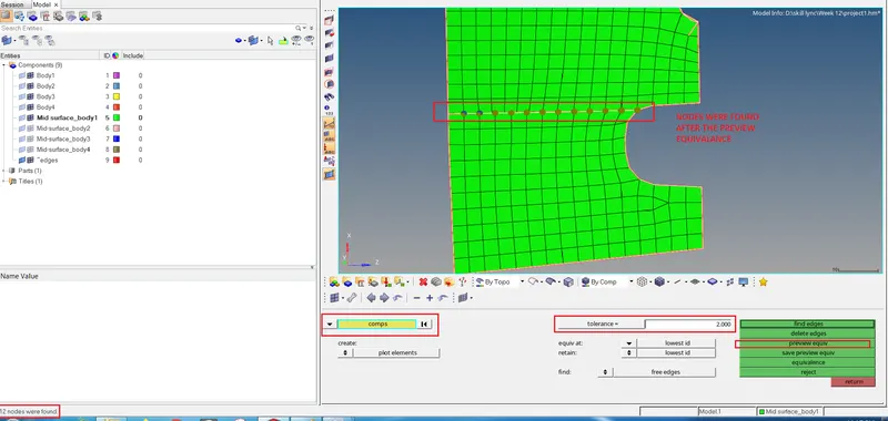
Fig 15 Carrying the pre view equivalence for discontinuous elements
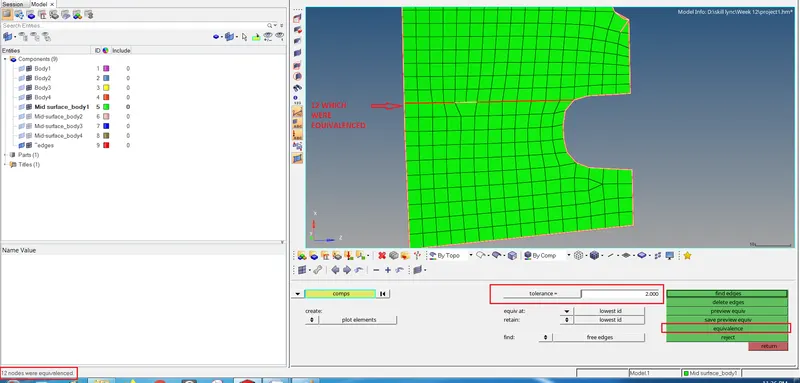
Fig 16 Equivalence of nodes
7)Elemental Quality Check :
The meshed element should be checked with the given quality criteria. The given quality criteria should be saved as the Criteria file in the preferences.
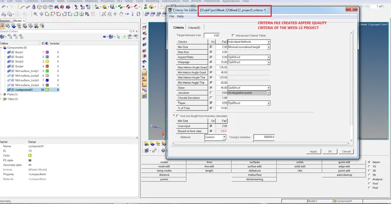
Fig 17 Criteria file creation as per the Quality criteria of the Week-12
The created Criteria file is applied and the elements failing for the criteria are identified using the Quality Index in 2d tools panel .
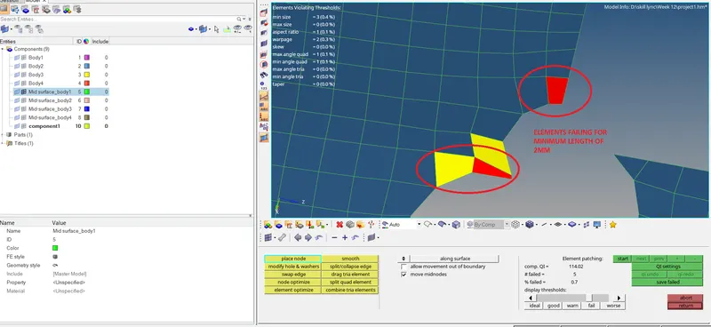
Fig 18 Identifying the elements failing for the Quality criteria using quality Index
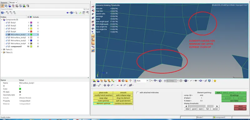
Fig 19 Elements failing for Minimum length after Elemental Clean-up
8)Adding thickness to the component :
i) Creating the Property:
In the Model Space, the property is created & the Thickness is entered in the property.
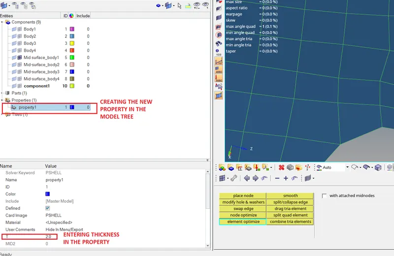
Fig 20 Creating new property in the model space
ii) Assigning the Property to the Component:
The Property created is assigned to the component by right-clicking on the component on which the property is to be assigned in order to assign the thickness. A thickness of 2.4 is given
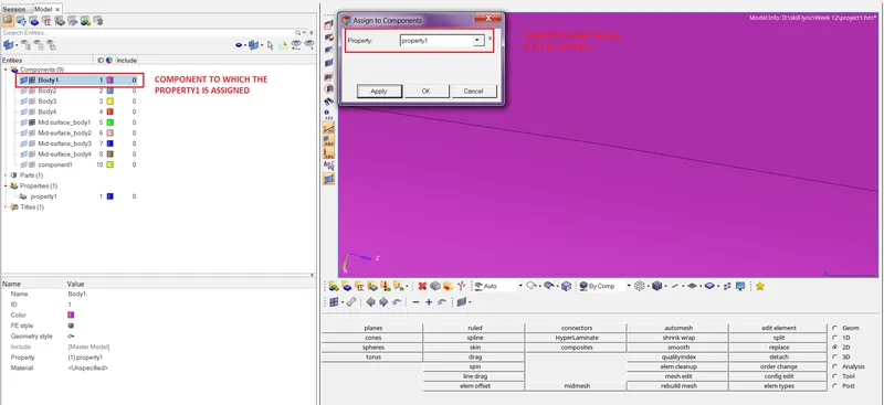
Fig 21 Assigning Property to the Component
RESULT:
1. The Mid-Surface for the given door-panel was succesfully generated
2. The Geometric Clean-up of the generated mid-surface was carried out succesfully.
3. The mesh with low-tria Concentration & proper mesh flow was generated successfully
4. All the elements of the mesh were made to conform to the given Quality criteria.
5. The Thickness to the component was assigned successfully.