Week 1:- Introduction to BiW and Fixtures Challenge
1. What is BIW and define its parts?
Body in White (BIW) refers to the welded sheet metal components which forms the vehicle structure to which the other components will be married i.e., engine, chassis, exterior and interior trim.
BIW refers to the stage in automotive design or automobile manufacturing in which the car body sheet metal (including doors, hood and deck lids) has been assembled or designed but before the components (chassis, motor) & trim (windshields, seats, upholstery, electronics etc.) have been added.
BIW parts are categorised into
1. Body sides : Body sides form the side structure of BIW assembly in a car. The body side parts mainly consists of
- A pillar - front most support to the roof.
- B pillar - second support to the roof.
- C pillar - is the rear most support to the roof incase of the two row seating system.
- Ring panel - a structure panel connecting rear and front portion.
- Quarter panel - rear most structure of a body side structure.
- Drip rails/gutters - an exposed channel appplied to the roof over the side windows to direct water away from the windows.
2. Under body : Under body of a BIW forms the base floor structure of the car. It is further subdivided into
- Front end under frame - It is the under body structure supporting the engine compartment of a car.
- Main floor - It is the under body structure supporting the seating compartment of a car.
- Rear end under frame - It is the rear end structure supporting the rear compartment of a car.
3. Closures : Closures are the hinged doors and mainly consists of
- Front door - is the door providing access to the front seats of a car.
- Rear door - is the door providing access to the rear seats of a car.
- Hood - is the door panel providing access to the engine compartment of a car.
- Deck lids - is the tail gate door providing access to the luggage compartment.
4. Roof : Roof is the part of BIW that sits above passenger compartment protecting the vehicle occupant from sun, wind, rain and other external elements.
- Roof inner : is the inner side of the roof surface.
- Roof outer : is the outer side of the roof surface.
5. Fender : Fender is the part of an automobile which frames the wheel well.
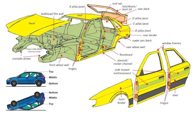
Image: BIW and its parts
2. What do you understand by BIW nomenclature?
BIW nomenclature refer to the naming or identification given to the BIW components of a car body.
Below images show the UK & US description of the BIW parts.
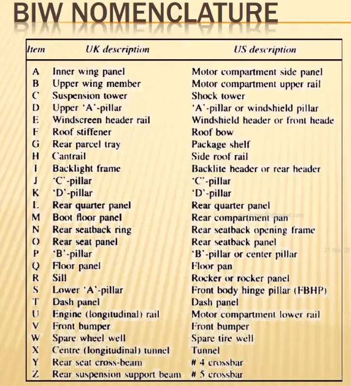
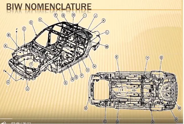
Image : BIW nomenclature
3. What is fixture and its type?
A fixture is a device which holds the workpiece to be processed (welded) by using 3-2-1 principles.
In general, a welding fixture (tool) consist of no. of units together to hold the car panel and is mounted on a base unit. Welding fixtures are normally designed to hold and support the various components (workpieces) to be welded. It is necessary to support them in a proper location which is capable of preventing distortions in a workpiece during welding. For this the locating elements need to be carefully placed, clamping has to be light but firm, placement of clamping elements has to be clear of the welding area and the fixture has to be quite stable and rigid to be quite stable and rigid to withstand the welding stresses.
Types of fixtures
- Production fixtures - These fixtures are used during the time of mass production. Before mass production all the difficulties in manufacturing and errors in the results are noted for the initial batch production and based upon it the fixture is modified to obtain defect free parts during the time of mass production.
- Pre production fixtures - These fixtures are used for initial batch production to study the feasibilty.
- Checking fixtures - These fixtures are used for the car panel geometric inspection purpose.
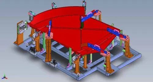
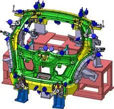
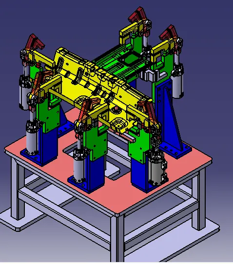
Images : BIW fixtures
4. What is the basic principle of fixture design?
The design intent of the fixture is considered on locating the work piece in a proper orientation and fixing it on the fixture to perform the desired operation on the work piece.
A free body possess 12 Degrees of freedom.
Six transational which are +X, -X, +Y, -Y, +Z,-Z
Six rotational which are Clockwise (CW) X, Anticlockwise (ACW) X, CW Y, ACW Y, CW Z, ACW Z.
So the 12 DOF should be restricted for the workpiece in a fixture.
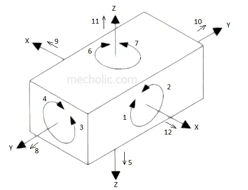
Image : 12 Degrees of Freedom
5. Elaborate types of BIW stations ?
The BIW assembly line is divided into sevral zones where different types of panels are joined together in each zone. Each zone has several stations which are :
1.Tool station : A tool is a fixture which consists of no. of units together to hold a car part in general.
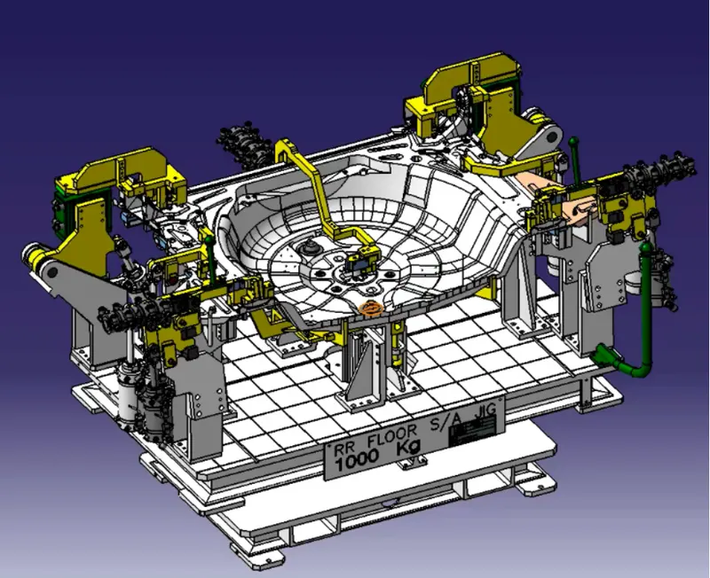
Image : Tool station (fixture)
These are further categorised as below:
1. Geo tool fixture : A geo tool is a fixture in which the geometry of the panels which are welded together is defined accurately. Teh pin tolerance for a geo pin will be of closer tolerance i.e. 0.15 in general.
For ex; Consider panel hole size 20mm, the pin diameter should be 19.85mm.
2. Respot tool fixture : A respot tool is a fixture in which the remaining weld spots which are not achieved in geo tool are welded for the pre welded panel from the geo tool. The pin tolerance for a respot pin will be of tolerance with -0.28 in general.
For ex; Consider panel hole size 20mm, the pin diameter should be of 19.72 mm.
3. Marriage tool : A marriage or hemming tool is a fixture in which the inner panel assembly and outer panel assembly are joined together fixture. These are done by welding or hemming in case of closure panels. In a marriage tool fixture the side bodies, under body, front body and rear body are joined together.
4. Framer tool fixture : A framer tool fixture is a fixture in which a roof is joined with output achieved from the marriage tool fixture.
5. Checking station Tool: A checking station tool is a fixture which is used to check the automotive parts or assemblies, ensuring all the coordinates, relative dimensions and positions as per the tolerances. A checking station can be a gauge type, fixed type and automated checking type.
2.Gripper stations : A gripper is a device or a fixture which holds the car panel and is fixed to the manipulating end of a robot or an end effector. Also known as EOAT - End of arm tooling.
Image : Grippers
Types of grippers:
1. Material handling grippers: Material handling grippers are designed for handling the car panel from one tool (station) to other tool (station)
2. Process grippers : Process gripper are designed for handling the car panel from one tool (station) to other tool (station) and in addition to that it undergoes processes like pedestal welding, pedestal riveting, gluing sealing etc.
3. Combo gripper : Combo gripper are designed for handling the car panel from one tool (station) to other tool (station) , Also with a combination of weld gun at another side of the gripper for welding.
4. Dual gripper : Dual gripper are designed for handling the car panel from one tool (station) to other tool (station), with two sided gripper.
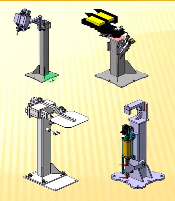
3.Stands stations :
Images : Stands stations
1. Gluing and sealer stand : Gluing gun or sealer gun is fixed to a welded or standard stand which is grouted to the floor.
2. Docking stand : When robots are selected for multitasking like material handling and welding, which cannot carry both due to some limitations (pay load capacity of the robot or space constraint) the robot will drop and pick the gripper or gun after completing the respective operation with the help of docking stand.
3. Date stamping stand : The panel will get the date embossed on it,with the help of date stamping device mounted on the date stamp stand
4. Pedestal stand : Weld gun is mounted to a fixed stand which is grouted to the floor permanently, where the process gripper carries the car panel to weld the spot with this fixed weld gun.
4. Miscellaneous stations :
1. Curing : Curing stations holds the workpiece for curing after gluing or welding is done on the workpieces so that the glue or weld undergoes curing.
2. Buffer stand : Buffer stand is used to store the workpieces so that the flow of the assembly line is maintained during the process with no short of workpiece.
3. Conveyers : Conveyers are the rotating belts which carry the workpiece from one tool (station) to other tool (station).
4. Take out trolleys : Take out trolley is used to take the car panel out from the robotic working cell between the cycle for inspection purpose.
6. What are the basic terminologies used in BIW fixtures?
The basic terminologies used in BIW fixtures are:
1. NC/Mylars/fingers : Mylars are the parts which holds the workpiece in a fixture. There are 2 types of mylars : clamping mylar and resting mylars.
2. PLP (Principle locating pins) : These are the pins which are used to locate the workpiece in a accurate position, so that we obtain the repeatabilty of results in a process.
3. Risers : Risers are L-type or square frame type. These are the structures which gives heights to the assembly.
4. Blades : These are the plates mounted on the risers, upon which the cylinders, pins etc. can be mounted
4. Shims : Shims are used between the clamping elements so that the clamping force is sufficient enough to hold the workpiece properly to avoid distortion and also do not cause any dents or damage on the workpiece by high force. Hence shims are used to rectify the stack up tolerancse of the clamping elements to avoid distortion and dents on the workpiece
5. Rough locators : Rough locators are the guides which help the operator to locate the workpiece in a proper orientation.
6. Hardwares : Hardwares are elements like bolts, fasteners, nuts etc.
7. CMM : Coordinate measuring machine is used to measure the coordinates of the features in a fixture as per the drawing.
8. Units : A fixture is an assembly of various units which can be a base unit, pin unit, clamp unit etc.
9. Number plate : A number plate is aluminium plate on which a number is embossed. These plates are placed on the fixture units for their recognition.
10. Name plate : A name plate provides the details of the fixture embossed on it.
11. Clamp arm : In a clamping unit the arm which moves and is responible for clamping is called clamping arm.
12. Pivot : A pivot is an elements about which axis the clamp arm swivels.
13. Class A surfaces : Class A surfaces are the outer most sufaces which is visible to the end customers and is responible for the aesthetics of a car. Hence the fixture units must be of soft material upon those surfaces to avoid any dents on it.
14. Reed switches and sensors : In automatic driven fixture, reed switches and sensors are used for clamping the part, where the sensor senses the workpiece upon which the reed switches activate to clamp the workpiece.
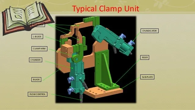
Image : BIW nomenclature