Suspension system Comparison
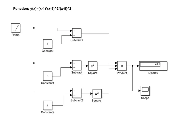
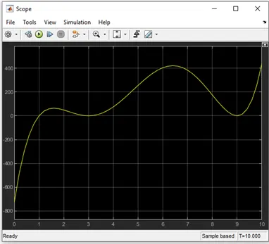
AIM: Plot a function using y(x)=(x-1)*(x-3)^28(x-9)^2 using simple Simulink blocks
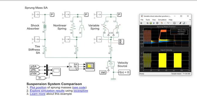
Run “Suspension system Comparison” Simulink model and explain the details.
Description:
The function y(x)=(x-1)*(x-3)^2*(x-9)^2 has three terms x-1, (x-3)^2 and (x-3)^2 . The input variable is ‘x ‘for which taken a ramp block. The Ramp block generates a signal that starts at a specified time and value and changes by a specified rate. Here the slope value, dx/dt=1 is taken which determines the rate of change of generated signal. Start time, t=10sec specifies the time at which the block begins to generate the signal. Initial output, x= 2 specifies the initial value of output signal. Constant block is used to provide constant signal inputs. Math operations were done as per function specified using substract and product block by taking variable input and constant input signals. The display block connects signal in the model and displays it value during simulation. Scope block displays signals during simulation.
Suspension System Model:
In modelling Suspension system, the main objective is to reduce the vibrations caused by different road surfaces so that comfort drive is provided. To reduce the vibrations we need to reduce suspension stiffness and at the same time should keep the suspension deflection within the acceptable limits. For this we may need to increase stiffness.
To achieve desired objective, we need to design a system level model and run simulations to optimize the design. We need to define the physical components of a system and their connections to observe the workflow. This approach facilitates rapid design iteration and exploration, leading to optimize design and improved understanding of how design parameters affect the system behaviour. Here our design parameters are stiffness and damping coefficient.
What is a simulation?
Simulation is the process of designing a model of a real system and conducting experiments with this model for the purpose of either understanding the behaviour of the system and evaluating various strategies for the operation of the system.
What are the similarities and differences in the three systems understudy?
A: Three systems are used to reduce the transverse vibrations which are created by sudden impact of loads(forced vibrations) applied to the object.
Similarities:
- In all the three sets, shock absorbers were used to generate resistance forces and are used with the elements spring and damper.
- All are given same velocity source and all three sets were provided with translational spring connectied in series with shock absorbers. This translational spring will absorb partial energy and generates frictional force such that the frequency of vibraions are reduced.
- All are provided with one sprung mass and unsprung mass and a Motion sensor block which will calculates the velocity and displacement values after passing through shock absorbers.
4.Shock absorbers were connected between sprung and unsprung masses in all sets.
Differences:
The first set uses the shock absorber block and include linear stiffness and damping. The initial spring force is zero if the initial deformation is set to zero. The damping force is the sum of viscous and Coulomb friction forces.
The second set uses shock absorbers with non-linear translational spring and Non-linear Translational Damper specified by symmetric polynomial.
Force, F=k1*x +sign(x)*k2x^2...+k5*x^5 where k1 through k5 are the first through fifth-order coefficients, x is the current deformation
Damp Force, F=b1*v+sign(v)*b2*v^2….+b5*v^5 , where b1 through b5 are the first through fifth-order coefficients and v is the velocity of port R minus the velocity of port C
Here we can give variable input as deformation only and can adjust the value by giving priority levels whereas in variable translational spring we can change variable input like force, velocity.
The third set uses a linear variable translational spring and Linear Variable Translational Damper system, with the oscillations of the mass caused by the initial deformation of the spring.
F=K*x, where k is the physical signal input and x is the current deformation. Minimum spring rate taken is 1 which prevents nonphysical negative
F=B*v, where B is the physical signal input and v is the relative velocity between connections R and C. Minimum damping coefficient (value= 0)prevents non-physical negative B values
The affect of simulation can be checked by changing variable initialization and also by setting its priority level(high, low, none). We can also specify different variable targets system initialization for force , velocity and check the simulation results and observe how it affects the system.
The spring constant is varied during simulation using open loop and damping coefficient is adjusts to ensure critical damping is achieved.
What are your observation from the results?
A:
When the first velocity input signal passes through all the three sets experiences, variable translational system shows minimum deflection or displacement compared to linear and nonlinear systems for first 20 sec. After this a time delay of 20 sec were given for the next input signal so that we can observe the behavior of all the systems. During this 20 sec, the variable system comes to zero displacement quickly whereas the linear and nonlinear systems takes time to come to rest due to inertia of masses. The second input signal is sent through where most of the energy is absorbed as well as dissipated in the form of heat in dampers and gives smaller range of deflection which slowly brings the masses to rest and experiencing less vibrations. When comparing the three systems, the variable suspension system produces smaller deflections. This is because in variable translational suspension system the stiffness and damping coefficient is being adjusted according the nature of load applied to the object and isolates the vibrations and performs better compared to other suspension system. When sending third velocity input, the variable system shows zero deviation while the other systems have lesser deviation.
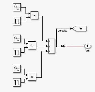
How the oscillating velocity source is created?
A: The three pulse inputs are generated with time lapse of 20 seconds and are added and given as a single input signal. These velocity input signals are the oscillating velocity source. each input velocity signal is sent to the system with a time delay of 20 seconds.
Suspension system Comparison Model and Graphs:
Referrence:
1. https://journals.sagepub.com/doi/full/10.1177/1687814016648638
2. Mathworks links
Conclusion: since the design will be optimized with less time through simulation method, the workflows follows the iterative steps used in traditional methods. so very few prototypes are required ,saves time and reduces cost also. In variable translational system ,by using closed loop the output is measured and is continously compared with the required value.