Doorbell using Solenoid and Thermistor to sense the themperature of heater.
AIM:
- To make a doorbell model with Simulink and observe the movements of plunger when the switch is closed for every 2 seconds and release.
- To make a Simulink model which uses thermistor to sense the temperature of heater and turn on or off the fan.
Working Principal of Door bell:
The doorbell uses a electromagnet called a solenoid. A solenoid is an electomagnet where the coiled wire surrounds a metal piston. The piston contains magnetically conductive metal, so it can be moved backward or forward by the electromagnetic field.
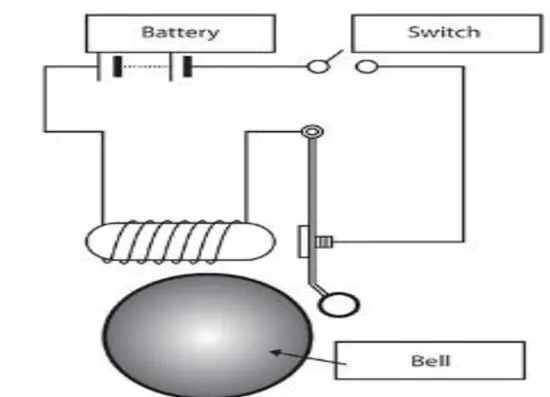
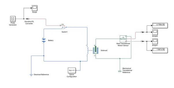
In our model , a square pulse is generated with a time delay of 2 seconds and is passed to the switch control. Now the switch block is controlled by the pulse generator. When the threshold value is less than the Physical signal value the switch closes and forms a closed circuit. The electric current is passed from the battery to the solenoid as soon as the circuit is closed . The solenoid contains a piston consists of iron core mounted on nonmetallic metal bar. When there is no power to the electromagnet, a spring pushes back the piston , and the iron core remains outside of the wire coil. When we turn ON the electromagnet by passing current, the iron core is drawn into the magnetic field. The iron core slides into the coil and strikes the end of the piston to the one hand tone bar which vibrates and produces the “ding” sound. As long we hold the doorbell button, the current will flow through the electro magnet and the piston remains in this position. Here the generated pulse is supplied to switch for a period of 2 seconds. So after two seconds get over the connection breaks and circuit becomes open. That means current will stop flowing through the electro magnet and the magnetic field collapse. The spring snaps the piston back to the initial position, where it hits the other tone bar on the other side. The second tone bar produces the “dong” sound. The process repeats until the last pulse of signal is generated.
The total time for signal is set for 10 seconds and pulse generated for every 2 seconds. During this period how the bell rings on and off is shown in the graph scope 1 and 2.
The ideal transformer motion sensor is used to monitor the position and velocity of plunger which is nothing but the piston for each pulse. The displacement and velocity values are shown in the display block.
Electrical and mechanical reference were given to each mechanical and electrical systems . A solver is provided to compute the states of the model during simulation or code generation.
Simulink Model:
scope1: Position of the plunger at each time it triggers
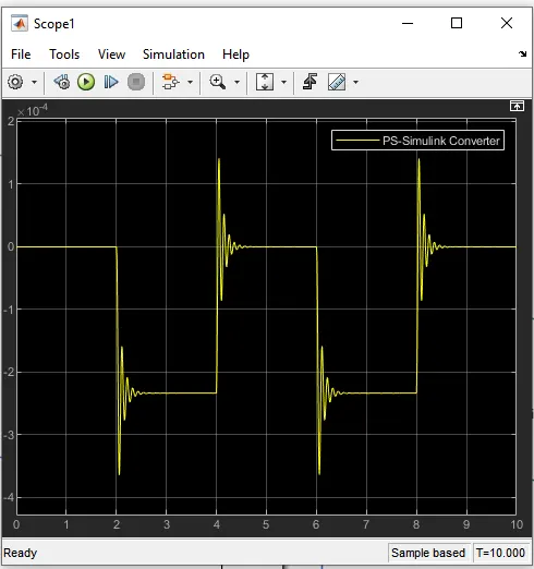
The above graph determines the position of plunger at the start of 2 seconds and end by 4th second. When the piston moves back it again hits the other end, vibrates and produces another bell sound and remains in its position until the next pulse passed. This repeats till the 10 seconds. At the start of 2 seconds the piston moved from initial position where initial position is set as zero to -234.672micro meters. At the end of 4 seconds the circuit breaks the piston moves back to initial position i.e.,zero position where it again hits the other end metal bar with force and produces another vibration wave.
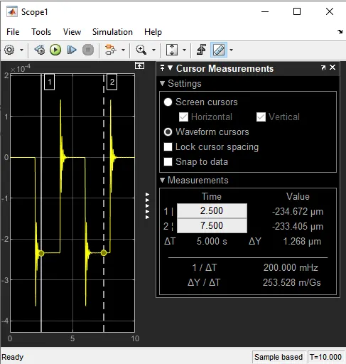
Showing the measurements of th positions of the piston at each time interval.
scope2: velocity of the plunger at each time it triggers.
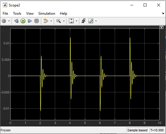
The above graph shows the vibrations produced by the tone bar at every 2 seconds.
Description: working principle of Thermistor:
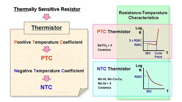
Thermistor is a temperature sensing element made up of semiconductor material which exhibits a large change in resistance proportional to the small change in temperature. Thermistors are of two types.
- Positive temperature coefficient thermistor,PTC whose resistance increases with increase in temperature.
- Negative temperature coefficient thermistor,NTC whose resistance decreases with increase in temperature.
Thermistor acts as a resistor with a high and negative temperature coefficient of resistance. Due to this property of high sensitivity that is huge resistance change for a small change in temperature, the thermistor is mainly applicable in precision temperature measurements in a low temperature ranges. It works on a principle that when a constant current flowing through the resistor and its changing resistance due to change in temperature is measured as a voltage drop across it.
Thermistor resistance-temperature relationship can be
dR=K* dT, where K is temperature coefficient, dR is change in resistance and dT is change in Temperature.
The negative temperature coefficient allows the thermistor circuit to detect minute changes in temperature which could not be observed by the other thermocouple circuits. Maximum limit of temperatures can be measured upto 100 degrees or 200 degrees.
Resistor: Resistor is an electronic component that limits or regulates the flow of electric current in an electronic circuit. These resistors are used to provide a specific voltage for an active device such as a thermistor which is also a resistor. The resistance towards the flow of current will result in voltage drop
R=V/I where R is Resistance, V is Voltage, I is current.
Electric current can be calculated by measuring the voltage drop over a precision resistor with a known resistance which is connected in series with the circuit.
Resistors regulates current in the circuit to the required parameter.
The temperature-resistance characteristic of a thermistor is non-linear and cannot be characterized by a single coefficient. We are using NTC thermistor which exhibit the characteristic of decrease in resistance with increase in temperature. A typical thermistor circuit is shown below
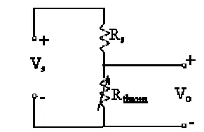
From the circuit diagram, it can be explained that this is a simple voltage divider. Rs is fixed resistor. Rs and the supply voltage ,Vs can be adjusted to obtain the desired range of voltage Vo for a given range of temperature.
Temperature Coefficient:
The resistivity of a material is dependent on the temperature and is normally given for room temperature. The change in resistivity as a result of temperature change is described by the temperature coefficient.
Thermistors uses this property to measure temperature. The temperature coefficient of resistance or TCR, is one of the main used parameters to characterize a resistor. The TCR defines the change in resistance as a function of the ambient temperature. The temperature coefficient of resistance for a resistor is determined by measuring the resistances values over an appropriate temperature range. The TCR is calculated as a the average slope of the resistance values over this interval
TCR= R2-R1/(R1(T2-T1)) * 10^-6 ,
where TCR is in ppm/oc, R1 is in ohms at room temperature, R2 is resistance at operating temperature in ohms, T1 is the room temperature and T2 is operating temperature.
Because the highest measured value is defined as TCR, this method often results in over specifying a resistor.
Description: Working principle of Electro mechanical converter:
Electro mechanical converter converts electrical energy to mechanical energy or mechanical energy to electrical energy via the medium of magnetic field or electrical field. When the conversion takes place from electrical to mechanical, the device is called motor. When the conversion takes place from mechanical to electrical then the device is called generator.
In our model we need to convert electrical energy source to mechanical energy source to run the fan which happens in the medium of electromagnetic field.
Let us see how it works.
- When the conductor is allowed to move in a magnetic field, the voltage is induced in the conductor
- When a current carrying conductor is placed in a magnetic field, then a mechanical force is experienced by the conductor.
When such conductors are placed on the rotor which is free to move, the electromagnetic torque produces on the rotor and that torque is transferred to the shaft of the rotor which can be utilized to drive the mechanical load. Since the conductor rotates in the magnetic field, a voltage is induced in each conductor. The rotor is driven by prime mover, the voltage is induced in the rotor conductor. When there is a voltage difference the current flows continuously through the conductor and produces magnetic field.
If the electric current or load via switch is allowed to pass through the winding of the motor, electric power is delivered to the load which is a fan in our model. The current flowing through the conductor will interact with the magnetic field to produce a reaction torque, which will tend to oppose the torque. The motor starts rotating and an ideal translational motion sensor is connected to the load so that the velocity of motor is measured and displayed in the scope block.
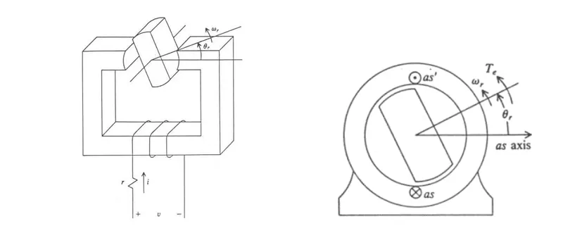
Conversion of Electrical energy to Mechanical Energy in magnetic field of coil
Objective of the Model:
Thermistor which is using as temperature sensor will measure the temperature of the heater and instruct the fan which is the mechanical energy source or DC motor taken, should be ON or OFF depending on condition given.
Given Data: Three temperatures were given as input temperature range for thermistor. `20^0` for 10 to 20 seconds,`27^0` for 10 to 30 seconds and `23^0` for 30 to 50 Seconds.
Condition: Fan should be ON if the temperature is above `25^0` and OFF if it is less than `25^0`.
Thermistor Simulink Model:Working Principle:
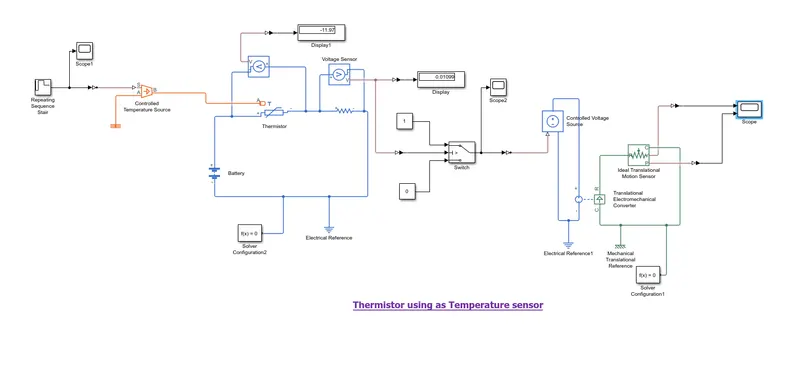
Using Repeating sequence star block a pulse is generated, which is range of temperature given in an array with a sample time of 10 seconds and total time of signal generated to observe is for 50 seconds. This signal is given to the thermistor through controlled temperature source block. Two inputs were given to the thermistor, one is the thermal input from controlled temperature source and other one is electric current from the battery.
When the temperature of the thermistor resistor increases i.e, when the temperature of the semiconductor increases and current passes through it, the number of active charge carriers increases which promotes them into the conduction mode. Due to the property of NTC thermistor, when temperature increases the resistance decreases. So more charge carriers nothing but electrons that are available tends to conduct more current. In our model the display 1 shows the value of voltage drop in negative values means more current flows through the conductor which is not desired. So to regulate the current we connect a resistor in series with the thermistor such the required voltage parameter is maintained. The display shows the desired value of voltage and is sent as input to the switch control. If the value is more than zero, the switch will changes to ON mode that means the circuit closes and current is passed to the DC motor. If the voltage value is less than zero, the circuit opens and the switch will be in OFF mode. No current is supplied to the DC motor.
Dc motor is a device which converts electrical energy to mechanical energy. here we have taken translational electromagenetic converter block which is nothing but a DC motor. Dc motor here palys a role of fan which is used to bring down the temperature of heater which we considered here with a controlled temperature sorce block for this model.
Now when the current passes to the DC motor, electromagnetic field generates over the winding coil. Due to this the voltage is induced in the conductor and current flows through controlled voltage source until the switch is ON. When the rotor is placed in the magnetic field, it receives electromagnetic force and starts rotating. Here the mechanical source is fan which starts rotating until the temperature of heater decreases.
Ideal translational motion sensor block is connected to motor by which we can taken the values of velocity and position of rotor and values can be viewed in display block also the graphs in scope block. We have given solver configuration to both the systems and electrical references are given to each circuit and mechanical reference given to the mechanical system.
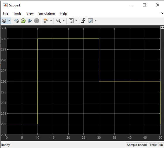
Input Data signal given To Thermistor to calculate Operating Temperature:
The three temperatures are given as controlled source input to thermistor using Repeated Sequence star block. The temperature array is given as data input [292 300 300 296 296]. Since the sample time is taken as 10 seconds. The second and third temperatures are repeated and values are given in kelvin.
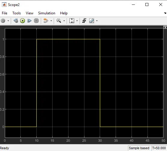
Input data of voltage given to the switch Block to check the condition :
Takes the voltage value which is obtained at operating temperature sensed by thermistor and pass to switch block. The switch check the value, if it is more than zero the current will pass to the fan and it will changes to ON mode. If the value is less than zero, no current will pass and the fan will in OFF mode.
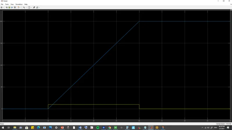
Output result : The graph shows the velocity and displacement of DC motor .
Conclusion:
Simulink models enables the users to experiment different working conditions of electrical and mechanical systems. Thermistors can be used in firm alarm device to avoid accidents, in laptops to maintain temperatures, in engine oil cooling systems to regulate the temperatures.
- Jiji MI have created a model for doorbell with solenoid similar to this, but I'm confused about the input value that is to be given. For the pulse generator, I have provided the period as 10 seconds and pulse width as 20%. While running the model, the output shows that there is position change in 0 to 2 secs as well. Do I have to provide a phase delay of 2 secs as well? Also, for the pulse generator, the pulses are created in every 10 seconds, is that because I provided the period as 10 secs, if yes, how can I change the pulses generated in every 2 secs, please help me with these?
- Udaya Jyothi KHi, yes we need to provide a phase delay of 2 seconds or any number of seconds but in regular intervals otherwise instead of ding -o- dong, the sound would be continuous. Next 2 to 4 seconds which we call phase delay for 2seconds , there will be no power supply, and the power circuit breaks. During this period the plate gets released from the electromagnetic field, it will hit the other hand of the tong due to momentum and the second sound is created. so we need to provide some phase delay in order to get the ding dong sound. we need to enter the delay value while providing pulse, step signal. when we press the bell button the pulse is generated for 10 seconds with a phase delay of 2 seconds. Yes while providing a pulse generator using a pulse generator block, u need to enter the parameters phase delay value as 2 seconds and period as 10seconds. If we don't enter the delay value only a single pulse with no step is generated.
- Jiji MThank you, Udaya.
- Jiji MHi, I tried this, but I'm not getting the pulse in every 2 seconds, after 4 seconds, there is no signal produces till 10 seconds. I have provided the phase delay for pulse generator as 2 sec, period as 10 sec, and pulse width as 20%. can you help me out?