STRUCTURAL ANALYSIS OF A BOLTED THRUSTER NOZZLE FLANGE
AIM:
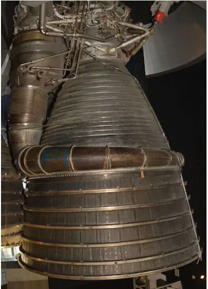
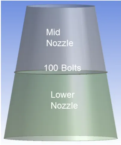
Analyzing the structure of Saturn V rocket first stage F1 engine bolted flange joint that connects the mid and lower nozzle by building a non-linear finite element model.
OBJECTIVES:
- Main objective is to assess the margin of safety of the flange bolts.
- Determine the gaps that develop between the jointed parts when the assembly is loaded.
- Study the sensitivity of the bolted nozzle flange results to key input parameters, we will explore the sensitivity of the bolted flange model to the following inputs:
- Load due to regeneration channels
- Bolt preload
- Coefficient of friction between flanges
SATURN V ROCKET FIRST STAGE NOZZLE:
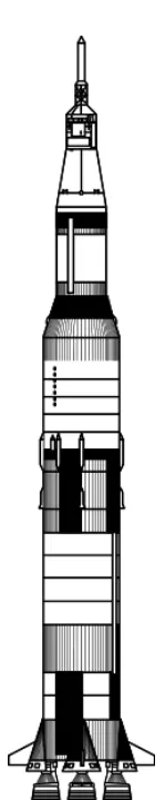
The Saturn V rocket that carried people to the moon is the most powerful machine ever built. The Saturn V's first stage was powered by five F1 engines.
MODEL:
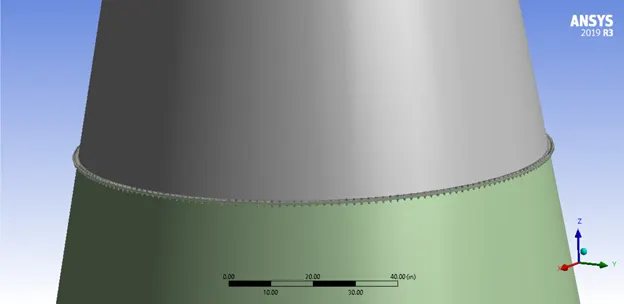
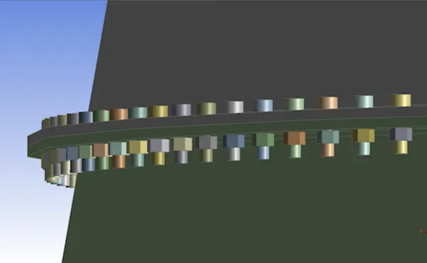
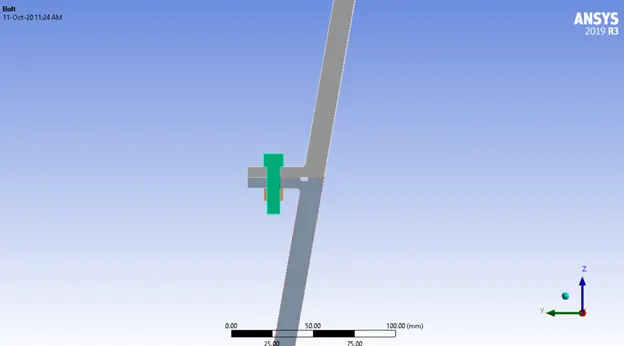
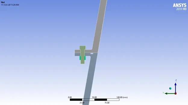
Using periodicity (& plane at 0.9 degree) the geometry is simplified to half a bolt from 200 bolts. The reduced model also contains part of mid and lower nozzle.
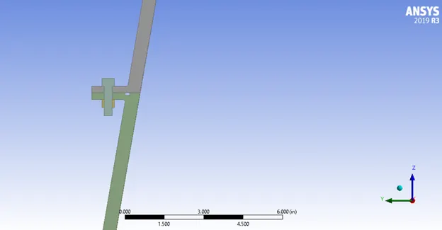
COMPONENTS:
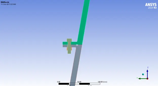
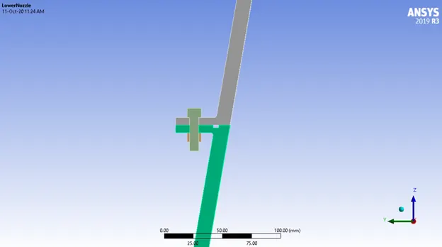
MESH:
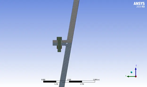
Mesh Method `->` Hex Dominant
Body Sizing 1 `->` Upper and Lower Nozzle `->` Element Size `->` 0.1 inch
Body Sizing 2 `->` Bolt & Nut `->` Element Size `->` 0.05 inch

MATERIAL PROPERTIES:
Update these properties and materials into engineering data and assign these materials to their respective models in ANSYS Mechanical.

LOAD SETUP:
Environment Temperature `->` 70o F
ESSENTIAL BOUNDARY CONDITIONS:
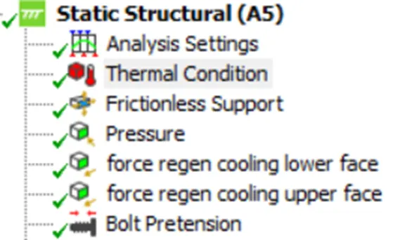
Analysis Settings `->` Number of load steps `->` 3s
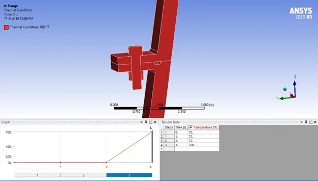
Thermal Condition `->` All bodies `->` Tabular
The gas temperature is 700 F which causes thermal strain.
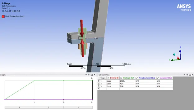
Bolt Pretension `->` Body `->` Select the Bolt Thread Face
We assume that bolt is pre-loaded to 50% of its breaking strength.
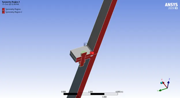
2 symmetry regions are defined so that in the analysis there would be no deformation axially.
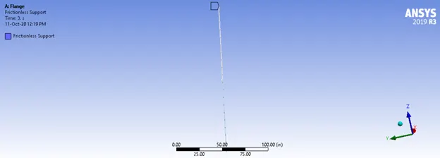
Frictionless Support `->` Mid Nozzle Top Face
NATURAL / TRACTION BOUNDARY CONDITIONS:
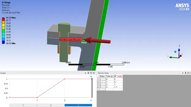
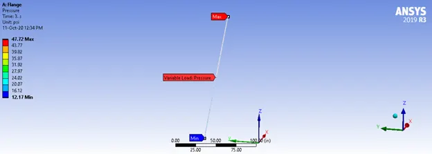
Pressure due to hot gas escaping through the nozzle
The pressure due to the exhaust gas in the nozzle is calculated using 1D gas dynamics. It is assumed to vary linearly along the nozzle axis. The pressure at the exit (z=0) is 12.17 psi and the pressure at the entrance to the mid-nozzle is 47.72 psi.

Load due to regeneration channel
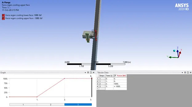
The regeneration channels are omitted in the model. In exchange, a free body diagram is used to deduce the equivalent forces on the mid nozzle and lower nozzle (the upper nozzle is not modeled here). This force pair is modeled as two separate forces, each of 1000 lbf.
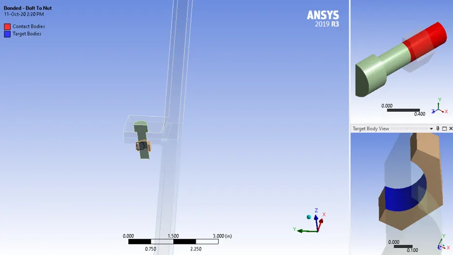
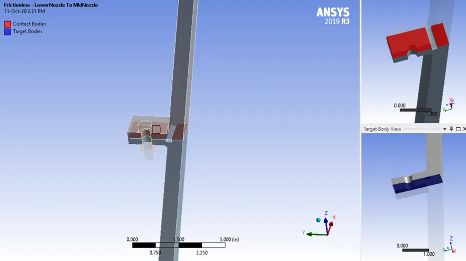
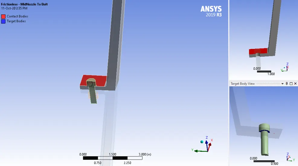
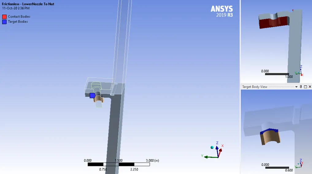
CONTACT SURFACES:
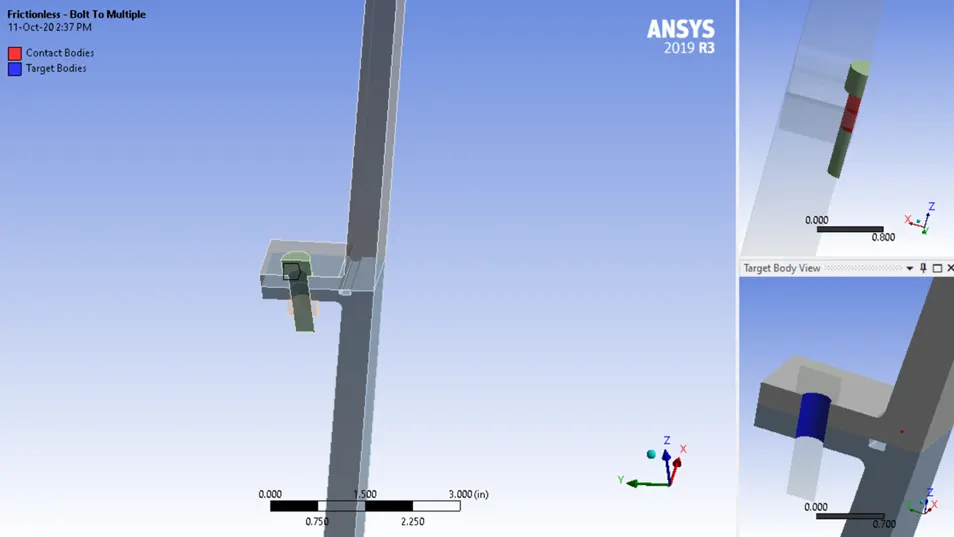
SIMULATION:
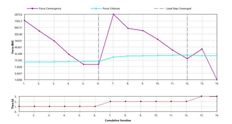
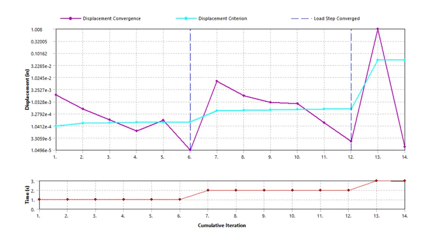
FORCE IN THE AXIAL DIRECTRION OF THE NOZZLE:

So, the Force Along The Axial Direction = -683.64 lbf (-ve for the -ve z direction)
By numerical equation,
Average Gas Pressure = `(12.17 + 47.72)/2` = 30 psi
Top Radius = 47.75 inch
Bottom Radius = 69.50 inch
Projected Area in Z direction =Px(69.52 – 47.752) = 9699 in2
Net Reaction Force on the – z direction = `(30*9699)/400` = 720 lbf (approx.)
So, the simultion result and the hand calculated values are aprroximately equal with a 5% error.
HOOP STRESS:
Using the normal stress option to evaluate the stress along the x direction to obtain the hoop stress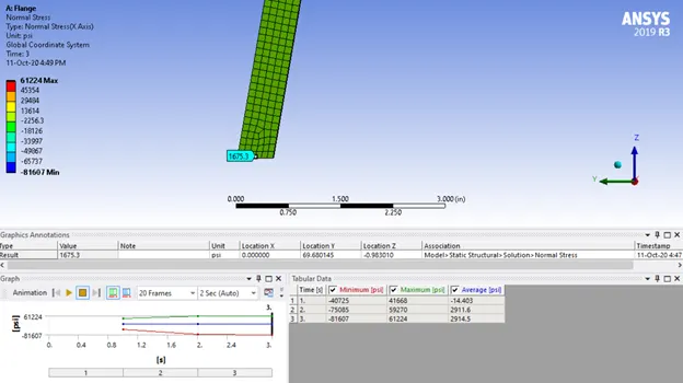
Hoop Stress (Normal stress in x direction) = 1675 psi
By numerical equation of a pressure vessel,
s = `(P*r)/t`
At exit:
P = 12.17 psi
r = 69.5 inch
t = 0.5 inch
s = `(12.17*69.5)/0.5` = 1692 psi
So, the simultion result and the hand calculated values are aprroximately equal with a 1% error.
TOTAL DEFORMATION DUE TO THERMAL STRESS:
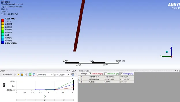
At time step = 3s
The Total Deformation = 1.0993 inch
By numerical equation,
ΔL= `α*ΔT*L`
Α = 1∗10−5oF-1 , ΔT = 630oF and L = 160 inches
ΔL = 1.008 inch
So, the simultion result and the hand calculated values are aprroximately equal.
Hence, the simulation is verified.
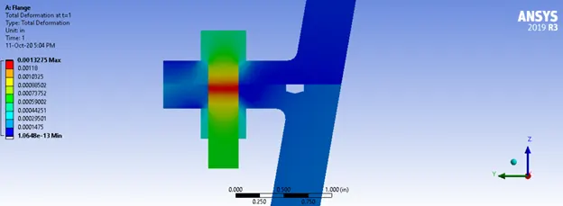
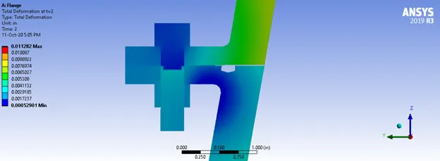
TOTAL DEFORMATION:
Time step = 1s
Time step = 2s, only bolt pretension is applied currently
Time step = 3s, Thermal stress is applied
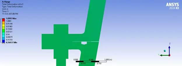
There would be deformation in axial and radial direction
EQUIVALENT STRESS:
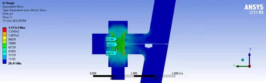
Stress due to bolt pretension =`2320/0.034` = 68235 psi
The both stresses obtained from the simulation above and hand calculation are similar.
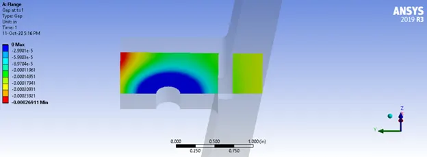
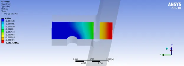
CONTACT GAPS:
At time step = 1s
At time step = 2s
At time step = 3s
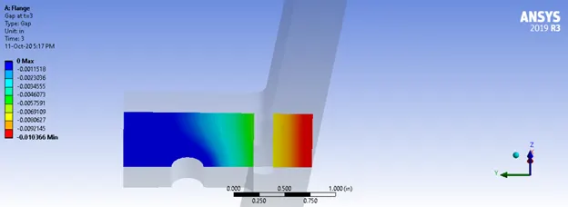
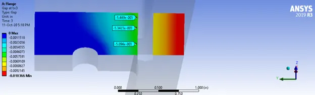
We can observe that there is minimal contact gap after the bolt. So, the sealing is actually within limits.
At time step of 3 sec, the gap after the O-ring is also minimal which would prevent the hot gas products from escaping the nozzle radially.
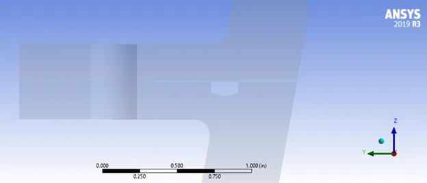
Actual true scale gap formed at the end of time step 3 sec
MODEL INPUT PARAMETER SENSITIVITY STUDY:
Changing 3 inputs to see its effects on the gap:
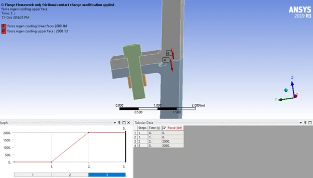
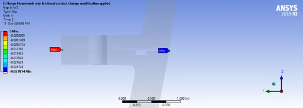
Change in force due to regenerative cooling `->` 1000 lbf changed to 2000 lbf on both sides (rest variables same)
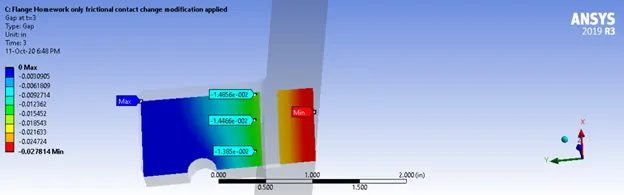
Change in bolt preload `->` 2320 to 1160 lbf (rest variables same)
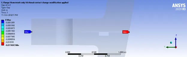
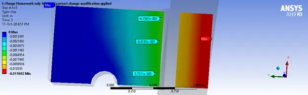
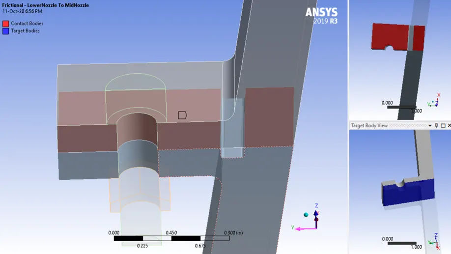
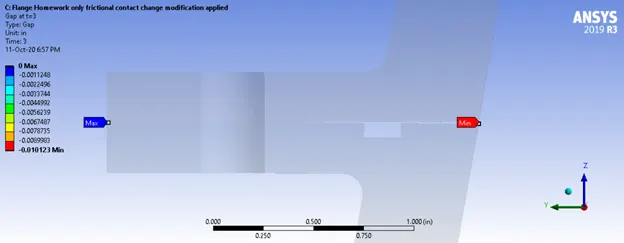
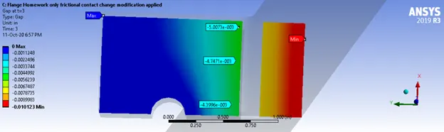
Changing frictionless contact to frictional contact in between lower and mid nozzle (coefficient of friction = 0.5)
CONCLUSION:
- A simulation study was carried on the bolted nozzle flange of the SATURN V F1 Stage.
- The deformations, stresses and the gap formed due the operational/mission loads was determined.
- Sensitivity to key parameters was studied:
- When the load due to regenerative cooling was changed from 1000 lbf to 2000 lbf (factor of 2) the gap was increased by a factor of 3.
- When the bolt pretension was changed from 2320 lbf to 1160 lbf (factor of 0.5) the gap was increased by a factor of 1.25.
- When the contact between the lower and mid nozzle was changed from frictionless to frictional contact surface with coefficient of friction of 0.5 the gap did not change.