COMBUSTION MODELLING OF TURBULENT FLAME IN A COMBUSTOR
AIM:
Performing a combustion simulation (Fuel | Oxidant - CH4 | Air) on the combustor and plotting the variation of the mass fraction of the different species.
OBJECTIVE:
NOX and soot are getting formed at the outlet of the combustor. Such formation has harmful effects on the environment and humans. The stringent government norms also demand the least formation of NOX and soot and to satisfy those requirements, so adding water content in the fuel from 5% to 30% by mole and observing the effect of it.
COMBUSTION MODELING
A large percent of worldwide energy conversion processes is based on combustion. Software from ANSYS offers a wide range of user-friendly models to simulate the interactions between flow, turbulent mixing, heat release and chemical reactions.
Non-Premixed Combustion
With the non-premixed (or diffusion flame) model, the turbulence–chemistry interaction is described using an assumed shape of probability density function (PDF). The thermodynamic state of the fluid, related to the mixture fraction and the chemistry is calculated either from equilibrium or by using a tabulated steady flamelet approach. The non-premixed model offers a robust and fast solution for any turbulent reacting ow that is at or near chemical equilibrium. This model is often used for gas turbine, process furnace and IC engine applications.
Premixed and Partial Premixed Combustion
For a premixed flame, an additional transport equation is solved for the reaction progress variable, flame surface density or distance to the flame front. The solution of this variable predicts the position of the flame front. For closure of the source term, ANSYS offers different proven correlations related to the turbulent burning velocity. These correlations provide the best practical method to predict turbulent premixed flames. In combination with the equilibrium or flamelet model, this approach is applicable to partially premixed and fully premixed combustion.
Turbulent Combustion
Because chemical kinetics are highly nonlinear, turbulence–chemistry interactions should be taken into account to accurately predict turbulent reacting flows. Fluid dynamics software from ANSYS offers a wide range of turbulence–chemistry interaction models of various complexities suitable for almost every turbulent reacting ow application.
Fast Chemistry (Used in this simulation)
The eddy dissipation model (EDM), in combination with the finite rate chemistry model, allows accurate simulation of the heat release and the distribution of the main chemical species for many industrial applications, such as gas turbines, internal combustion engines, furnaces and thrusters. The EDM can be used for all types of combustion as well as in combination with advanced scale-resolving turbulence and multiphase models.
SOOT MODELLING:
Soot models can be classified on the basis of their complexity and computational effort involved. According to Kennedy, a distinction can be made in three categories: empirical, semi-empirical and detailed models. One of the most known empirical models was proposed by Khan to predict soot emissions in diesel engines and neglecting particle growth and oxidation rates, estimates soot formation as a function of pressure, temperature and equivalence ratio of unburnt gases. A more accurate description of the physics can be obtained with semi-empirical models that include the chemical processes involved in soot formation, for example, expressing particle inception and surface growth on the basis of PAH concentration. Lindstedt exploited simplified reactions to describe the formation and growth of soot particles in laminar non-premixed ethylene and propane flames, using benzene and acetylene as precursors. Other example are given by Fairweather and Brookes and Moss, which differ for the choice of the precursor to soot nucleation, the model constants or the oxidation mechanism. High-fidelity predictions in a wider range of fuels and operating conditions require to account for the dependency of soot inception and surface growth on the PAH concentration. Detailed chemistry mechanisms are required to estimate PAH formation, whereas additional pathways should be considered for surface reactions, as well as the agglomeration of soot particles in complex agglomerate structures. This is accomplished with Monte Carlo models, sectional methods or methods of moments.
Systems of water supply into the combustion chamber
There are basically three methods of supplying water into the cylinder of an engine:
- Supplying appropriately prepared water with the scavenging air through the so-called low-pressure system;
- Injecting prepared water directly into the combustion chamber through an independent injector or a specially constructed fuel injector with a nozzle equipped with two needles;
- Injecting the FWE prepared in the fuel system by means of a standard injector but with increased capacity
Continuous water injection (CWI)
The continuous water injection is a relatively simple method of the NOX reduction by 30% and soot reduction by 25% without any engine modification. Water mist is injected directly into the hot compressed air at the outlet of the turbocharger. It is not recommended to exceed 25% of water content for the CWI due to significant increase of specific fuel consumption and adverse influence on the combustion process.
Humid air motor (HAM)
The humid air motor is a technology using water-saturated scavenging air for the main propulsion marine engines. The HAM is based on the rule of adding water to the charging air which reduces the NOX emission into the air by 60–80%.
The system of direct water injection (DWI) (Used in this simulation)
The direct water injection (DWI) is another method in the wet technologies group. It has the following advantages: during the maneuvers and low engine load, there is a possibility of supplying large amounts of water without disturbing the combustion process in the cylinders and of controlling the timing and the amount of the injected water dose to obtain the optimal NOX emission reduction.
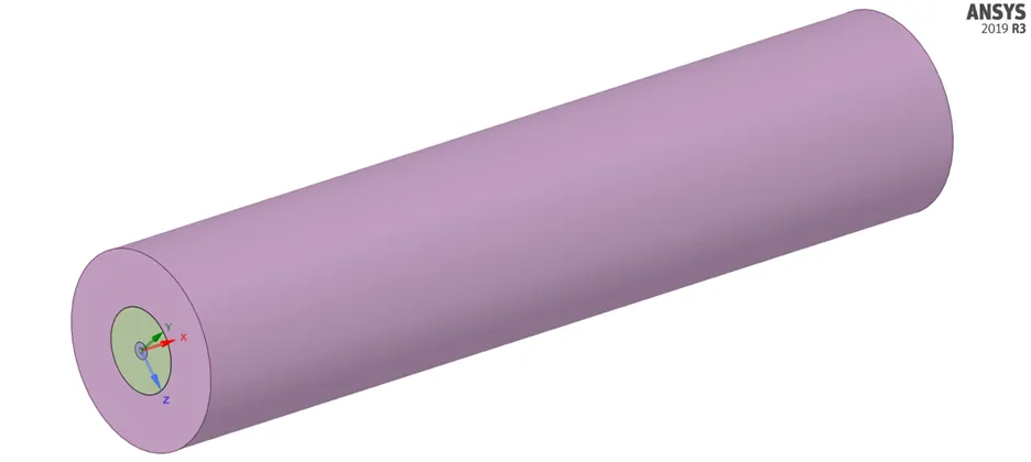
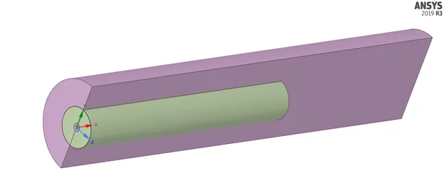
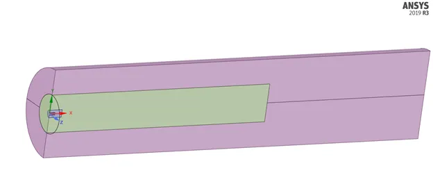
COMBUSTION CHAMBER (CYLINDER) MODEL:
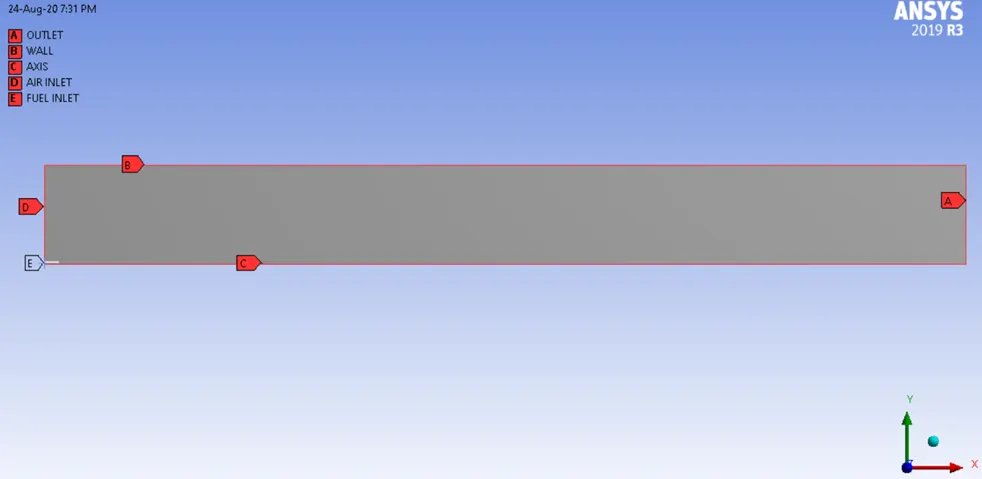
Model comprises of the fuel inlet, air inlet and the combustion region.
2D MODEL:
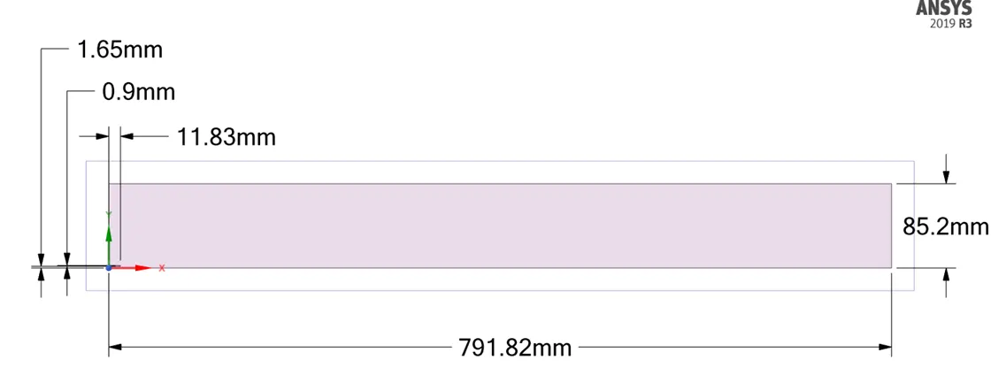
Extracted from the 3D model using split body command and combined the surfaces. This is done, so as to perform an axisymmetric analysis using fluent.
BOUNDARIES:
MESH:
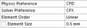
Method `->` All Triangles
Capture Proximity `->` Yes
Number of Cells Across Gap `->` 3

STEADY-STATE SMULATION SETUP:
2D Space `->` Axisymmetric
Pressure based solver
Energy Equation `->` Turned on
Viscous Model `->` K-epsilon Standard Turbulence Model `->` Standard Wall Functions
SPECIES MODEL:
Model `->` Species Transport
Reactions `->` Volumetric (Since Reactions takes place in gas)
Inlet Diffusion `->` Turned On
Diffusion Energy Source `->` Turned On
Turbulence-Chemistry Interaction `->` Eddy Dissipation (Self Ignition Model)
Mixture Material `->` Methane-Air-2Step
Number of Volumetric Species `->` 6
NOX Model `->` On `->` Pathways = Thermal NOX & Prompt NOX `->` Fuel Species `->` CH4
Soot Model `->` On `->` One-Step `->` Species Definition `->` Fuel = CH4, Oxidant = O2
Solution Methods `->` Pressure-Velocity Coupling `->` Scheme = SIMPLE
BOUNDARY CONDITIONS:
AIR INLET `->` Velocity = 0.5 m/s
Temperature = 300 K
FUEL INLET `->` Velocity = 80 m/s
COMBUSTION OF CH4 IN AIR:
Empirical Equation:
CH4 + ar (O2 + 3.76 N2) `->` aCO2 + bH2O + cN2
1 = a, 4 = 2b, 2ar = 2a + b, c = ar*3.76
a = 1, b = 2, ar = 2, c = 7.52
CH4 + 2 (O2 + 3.76 N2) `->` CO2 + 2H2O + 7.52 N2
FUEL `->` 1 Mole (Mole Fraction and Mass Fraction) CH4
AIR `->` 2 Mole O2 + 7.52 Mole N2
Mole Fraction O2 = `2/9.52` = 0.21
Mass Fraction O2 = 0.23
Mole Fraction N2 = `7.52/9.52` = 0.79
Mass Fraction N2 = 0.77
LINE PROBES:
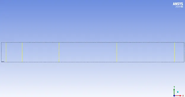
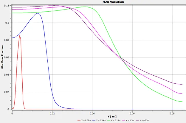
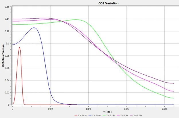
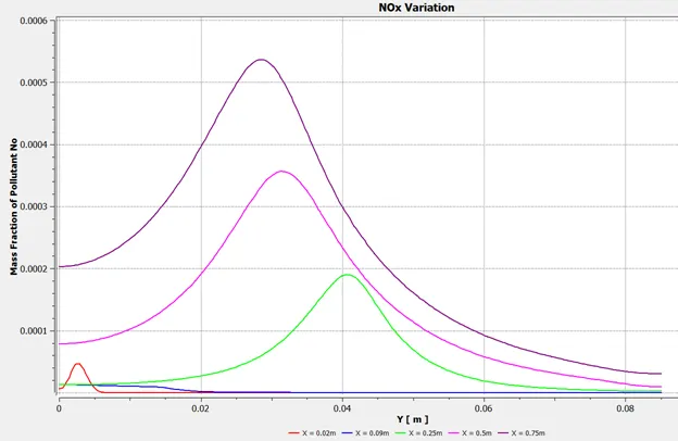
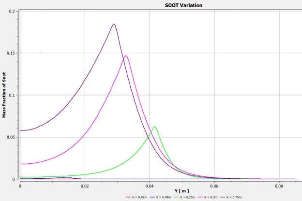
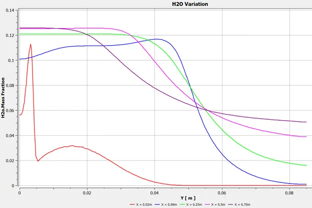
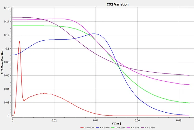
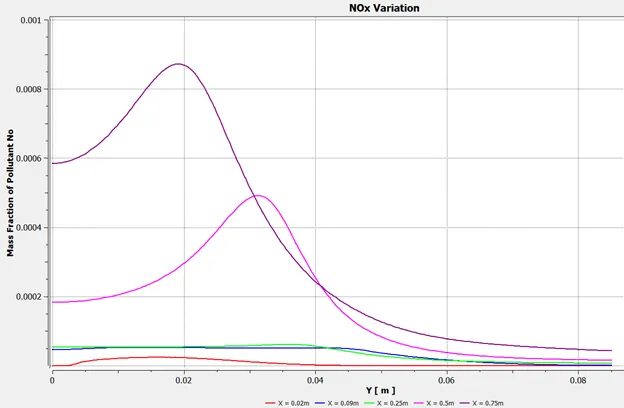
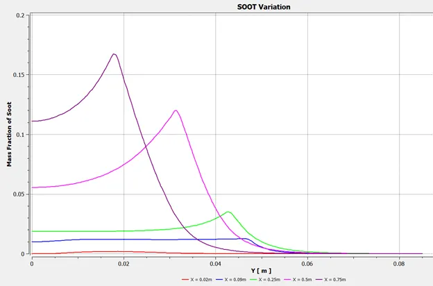
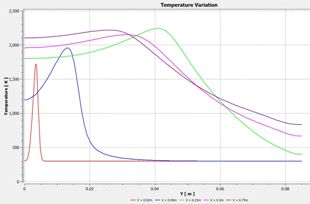
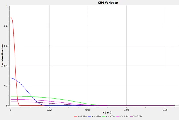
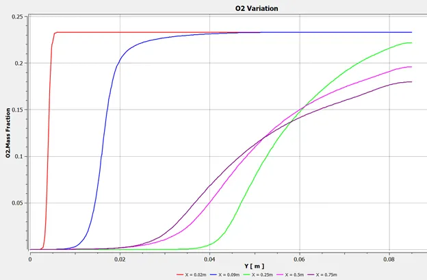
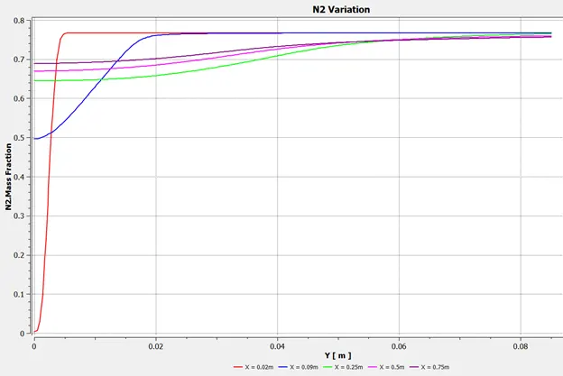
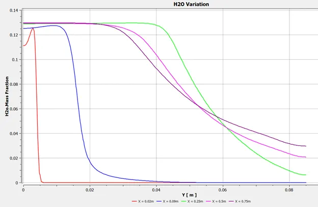
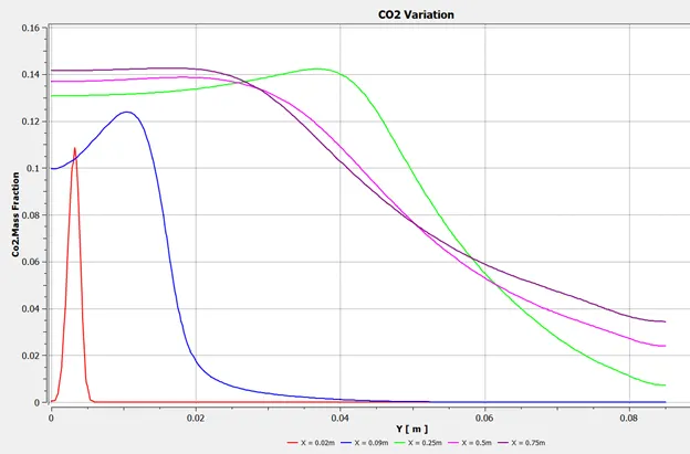
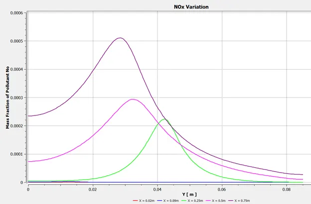
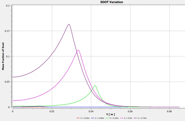
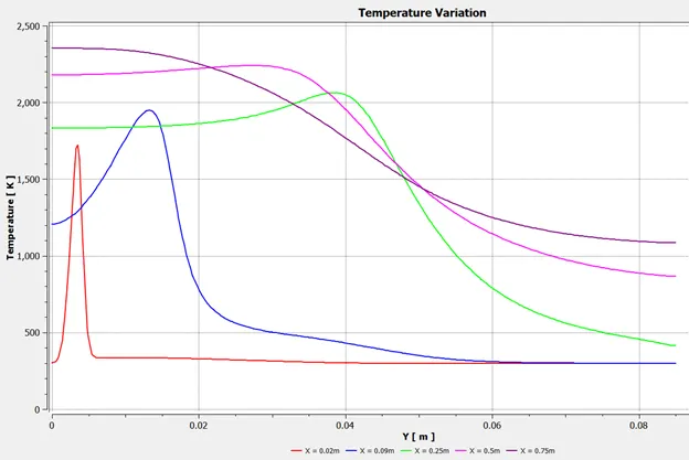
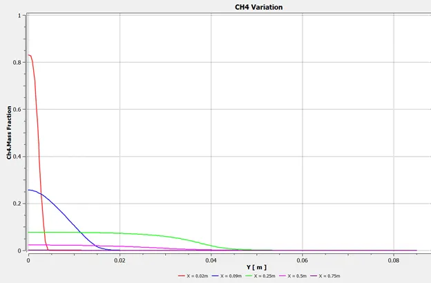
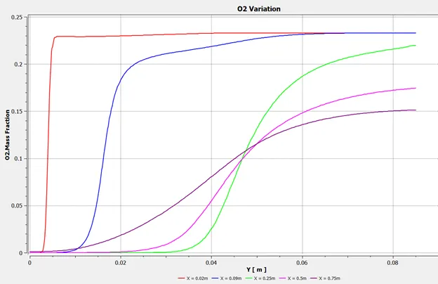
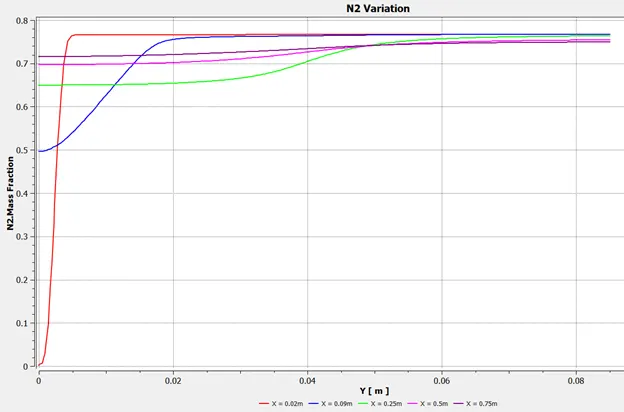
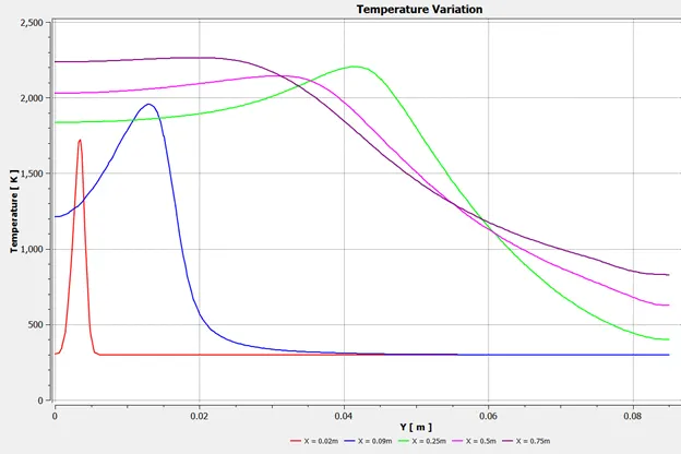
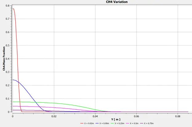
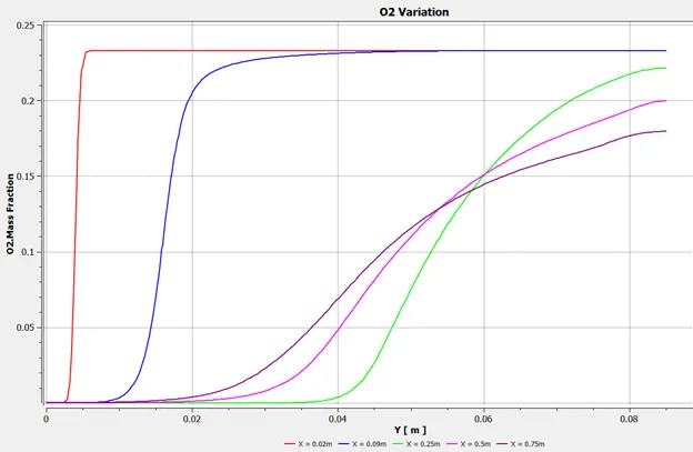
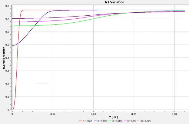
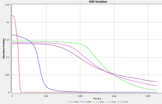
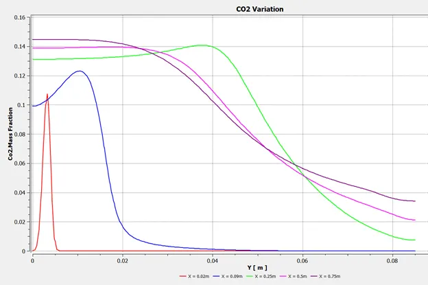
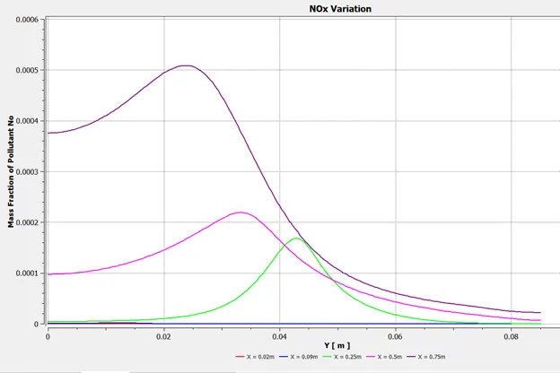
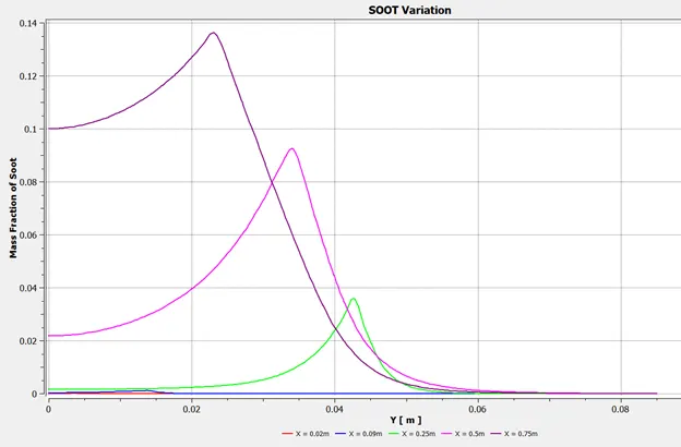
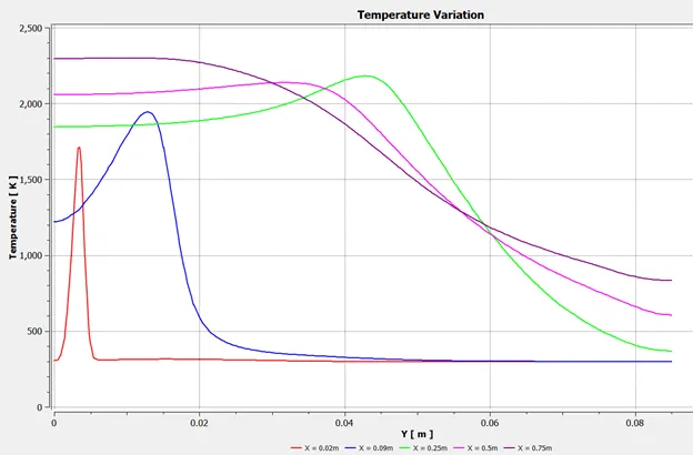
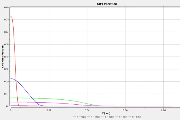
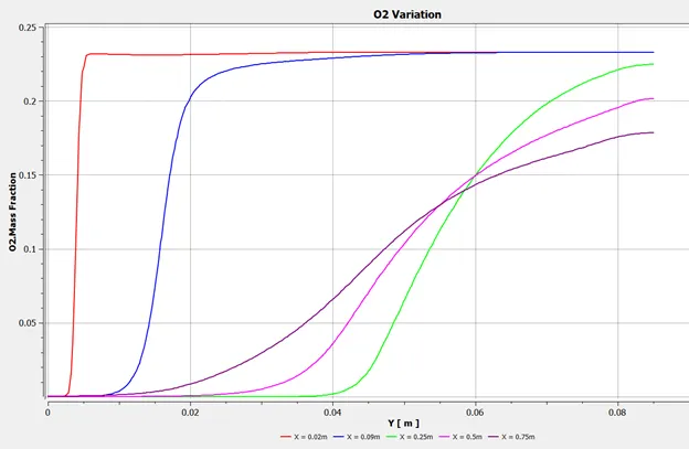
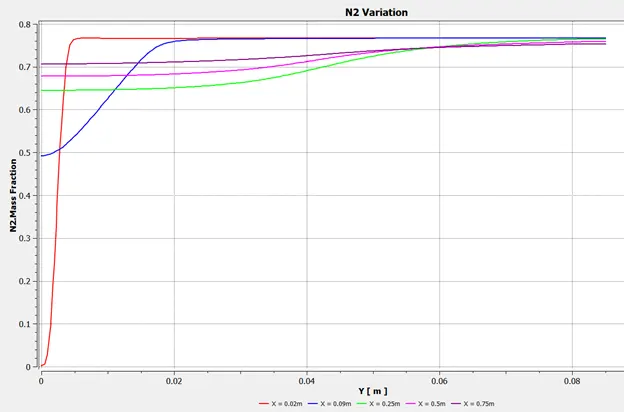
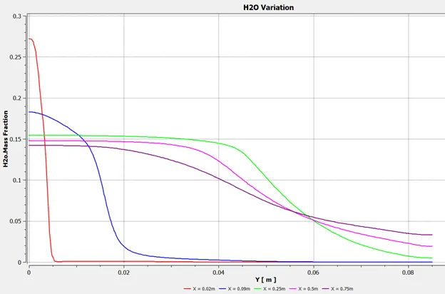
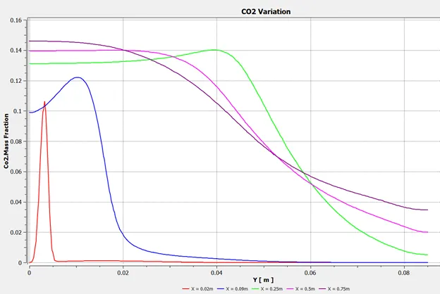
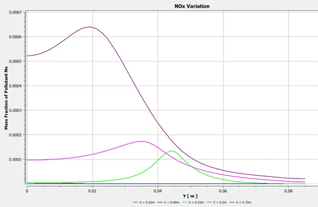
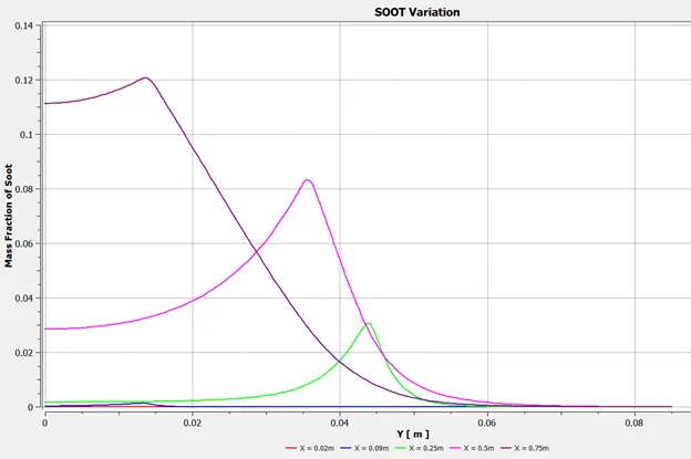
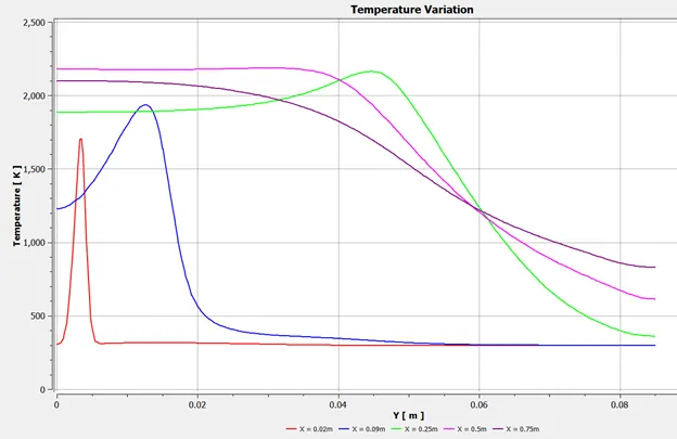
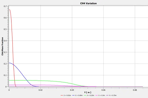
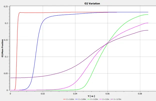
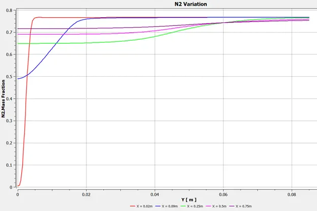
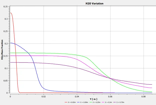
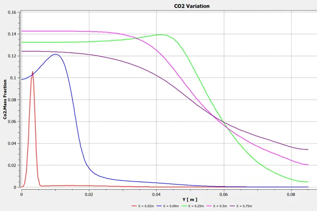
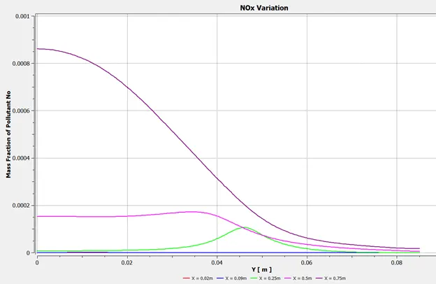
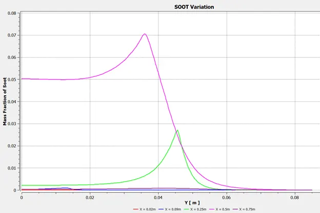
Line probes located at X = 0.02 m, X = 0.09 m, X = 0.25 m, X = 0.5 m, X = 0.75 m
CASE 1:
AIR INLET `->` Species `->` Species Mole Fraction `->` O2 = 0.21, CH4 = 0, CO = 0, CO2 = 0, H2O = 0
FUEL INLET `->` Species `->` Species Mole Fraction `->` O2 = 0, CH4 = 1, CO2 = 0, CO = 0, H2O = 0
Hybrid Initialization
Number of Iterations Given to Run = 1500
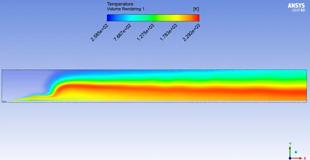
Temperature Volume Render:
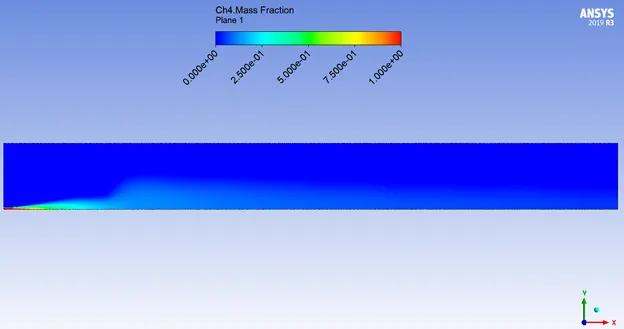
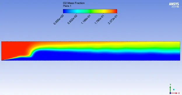
Fuel & Oxidant Contour:
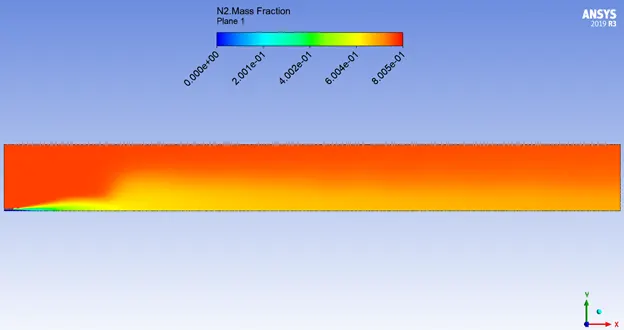
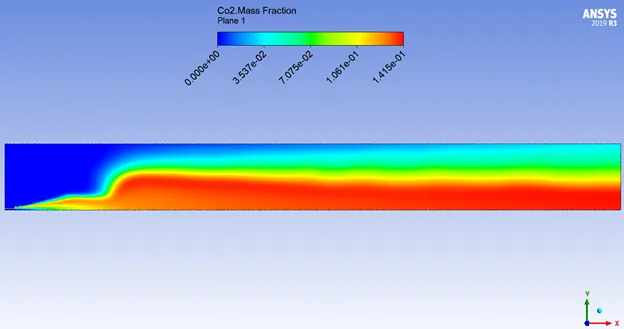
Inert & Non-Pollutant Combustion Products Contour:
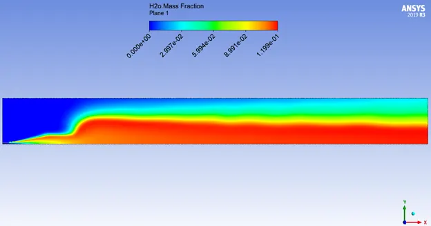
Pollutant Combustion Products Contour:
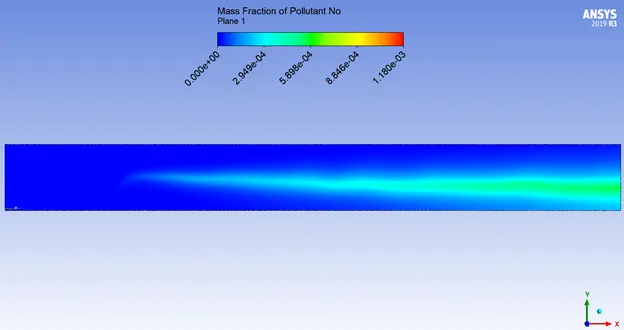
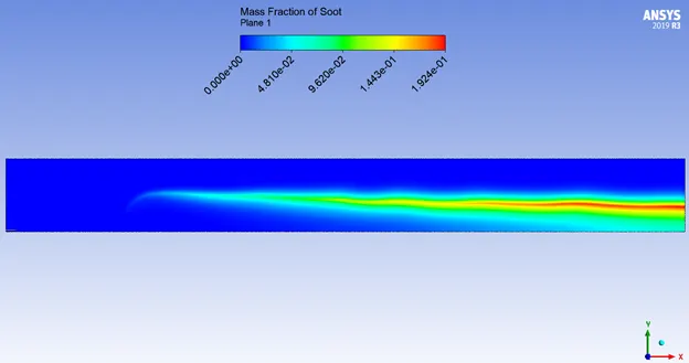
Variation Plots:
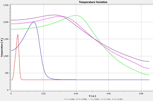
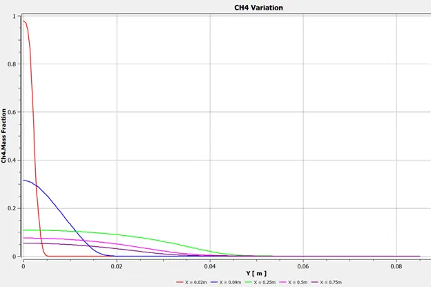
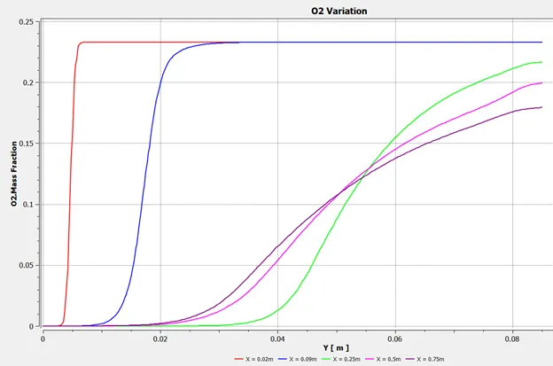
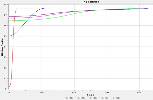
CASE 2 (ADDING WATER CONTENT IN FUEL BY MOLE 5%):
AIR INLET `->` Species `->` Species Mole Fraction `->` O2 = 0.21, CH4 = 0, CO = 0, CO2 = 0, H2O = 0
FUEL INLET `->` Species `->` Species Mole Fraction `->` O2 = 0, CH4 = 0.95, CO2 = 0, CO = 0, H2O = 0.05
Hybrid Initialization
Number of Iterations Given to Run = 1500
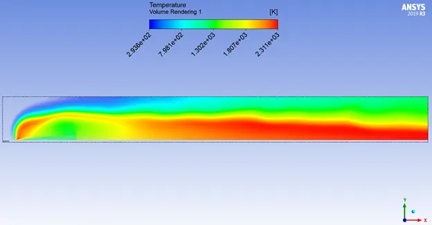
Temperature Volume Render:
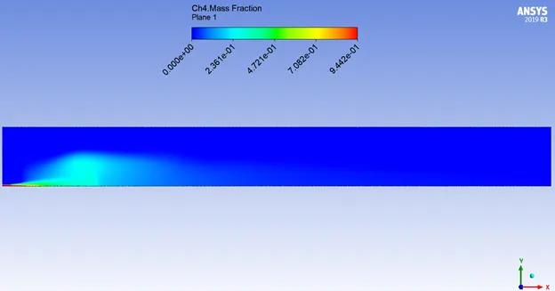
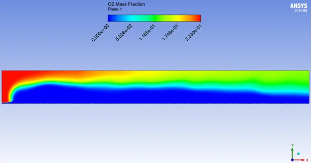
Fuel & Oxidant Contour:
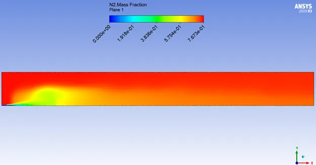
Inert & Non-Pollutant Combustion Products Contour:
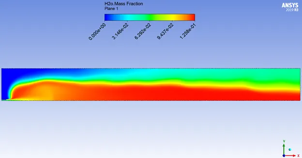
Pollutant Combustion Products Contour:
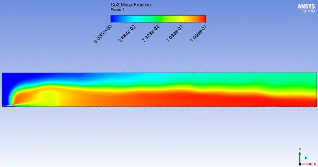
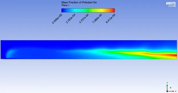
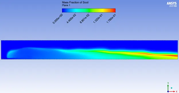
Variation Plots:
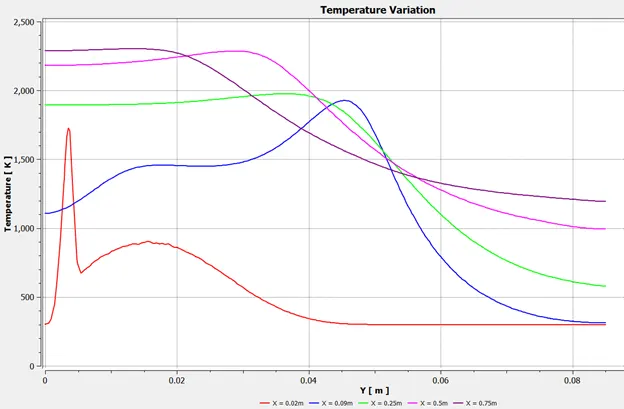
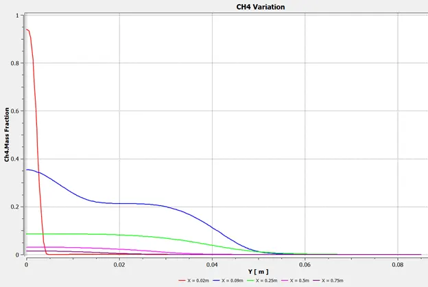
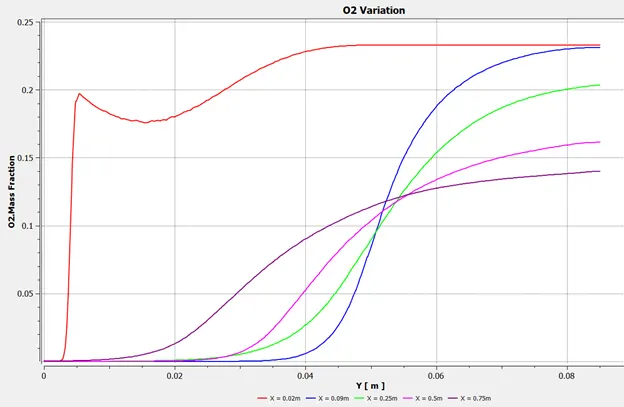
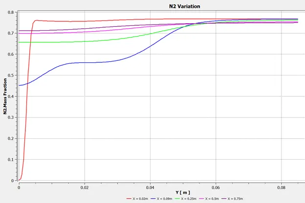
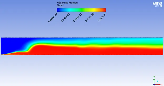
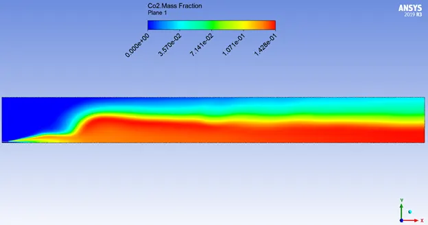
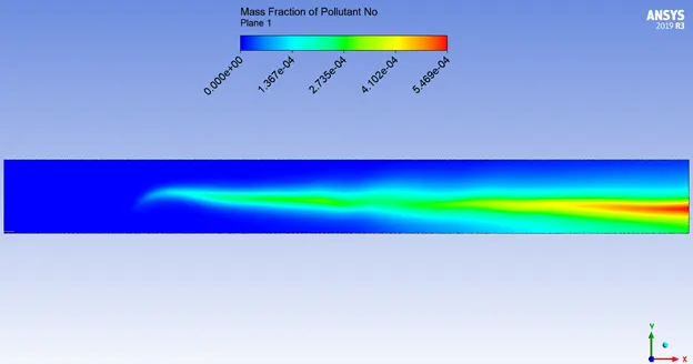
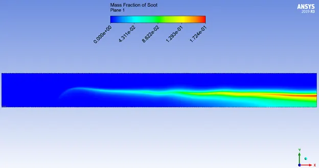
CASE 3 (ADDING WATER CONTENT IN FUEL BY MOLE 10%):
AIR INLET `->` Species `->` Species Mole Fraction `->` O2 = 0.21, CH4 = 0, CO = 0, CO2 = 0, H2O = 0
FUEL INLET `->` Species `->` Species Mole Fraction `->` O2 = 0, CH4 = 0.9, CO2 = 0, CO = 0, H2O = 0.1
Hybrid Initialization
Number of Iterations Given to Run = 1500
Temperature Volume Render:
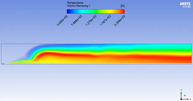
Fuel & Oxidant Contour:
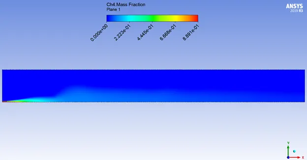
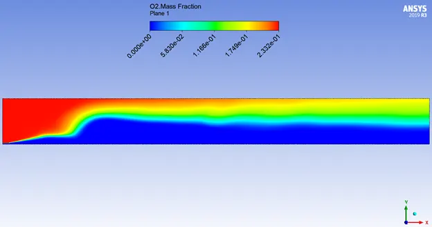
Inert & Non-Pollutant Combustion Products Contour:
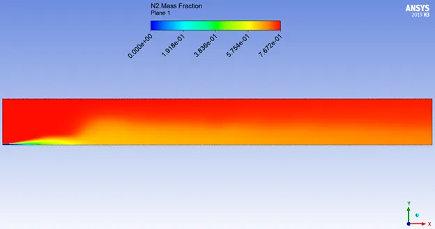
Pollutant Combustion Products Contour:
Variation Plots:
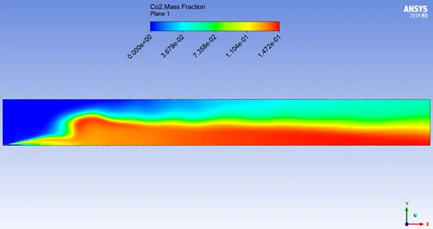
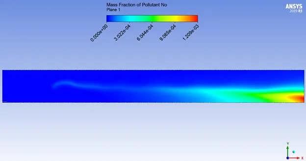
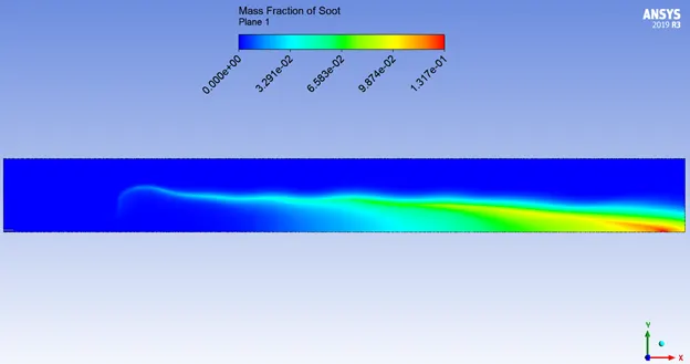
CASE 4 (ADDING WATER CONTENT IN FUEL BY MOLE 15%):
AIR INLET `->` Species `->` Species Mole Fraction `->` O2 = 0.21, CH4 = 0, CO = 0, CO2 = 0, H2O = 0
FUEL INLET `->` Species `->` Species Mole Fraction `->` O2 = 0, CH4 = 0.85, CO2 = 0, CO = 0, H2O = 0.15
Hybrid Initialization
Number of Iterations Given to Run = 1500
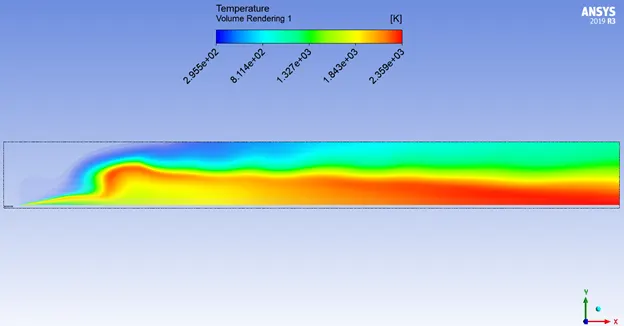
Temperature Volume Render:
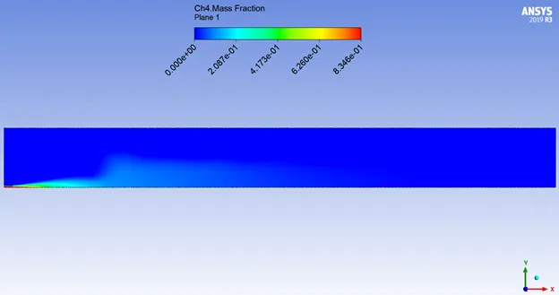
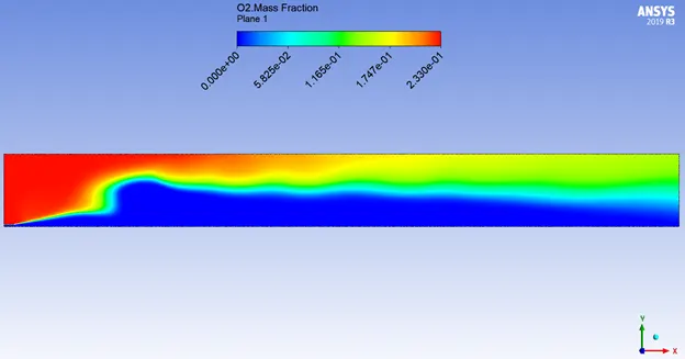
Fuel & Oxidant Contour:
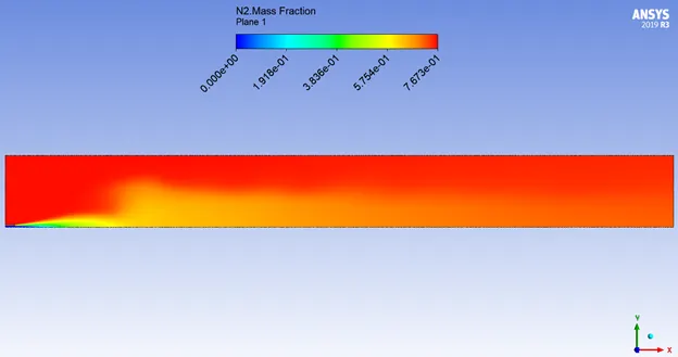
Inert & Non-Pollutant Combustion Products Contour:
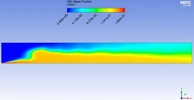
Pollutant Combustion Products Contour:
Variation Plots:
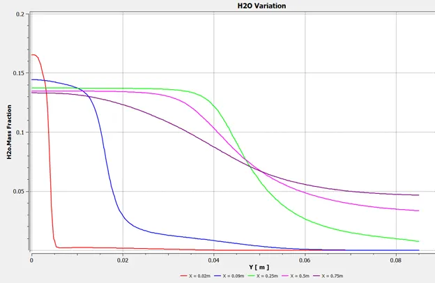
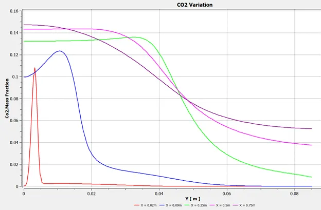
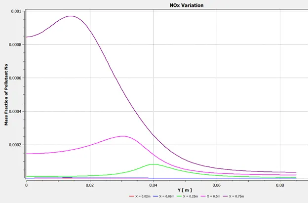
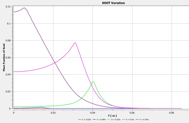
CASE 5 (ADDING WATER CONTENT IN FUEL BY MOLE 20%):
AIR INLET `->` Species `->` Species Mole Fraction `->` O2 = 0.21, CH4 = 0, CO = 0, CO2 = 0, H2O = 0
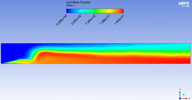
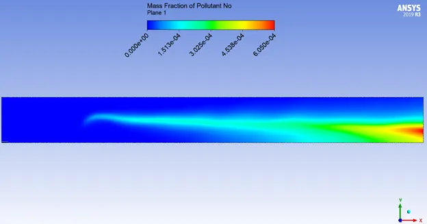
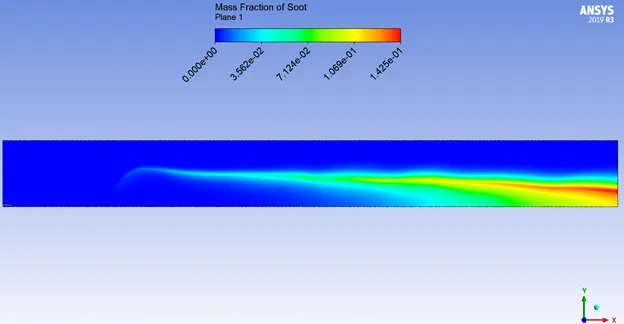
FUEL INLET `->` Species `->` Species Mole Fraction `->` O2 = 0, CH4 = 0.8, CO2 = 0, CO = 0, H2O = 0.2
Hybrid Initialization
Number of Iterations Given to Run = 1500
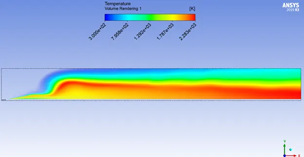
Temperature Volume Render:
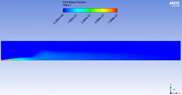
Fuel & Oxidant Contour:
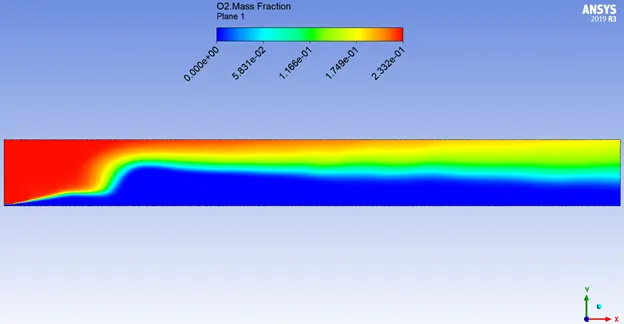
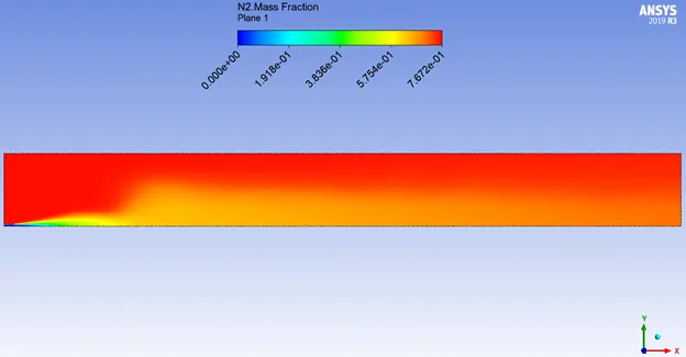
Inert & Non-Pollutant Combustion Products Contour:
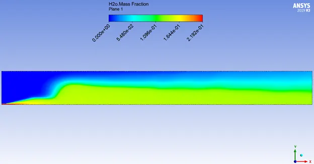
Pollutant Combustion Products Contour:
Variation Plots:
CASE 6 (ADDING WATER CONTENT IN FUEL BY MOLE 25%):
AIR INLET `->` Species `->` Species Mole Fraction `->` O2 = 0.21, CH4 = 0, CO = 0, CO2 = 0, H2O = 0
FUEL INLET `->` Species `->` Species Mole Fraction `->` O2 = 0, CH4 = 0.75, CO2 = 0, CO = 0, H2O = 0.25
Hybrid Initialization
Number of Iterations Given to Run = 1500
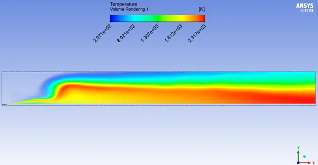
Temperature Volume Render:
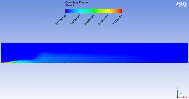
Fuel & Oxidant Contour:
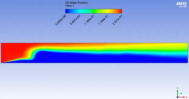
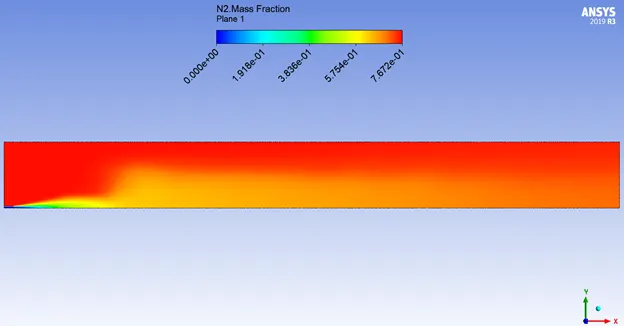
Inert & Non-Pollutant Combustion Products Contour:
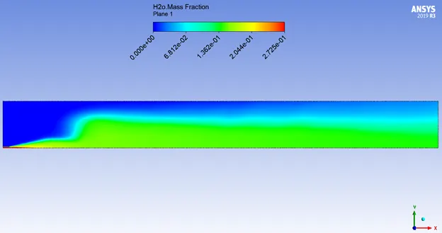
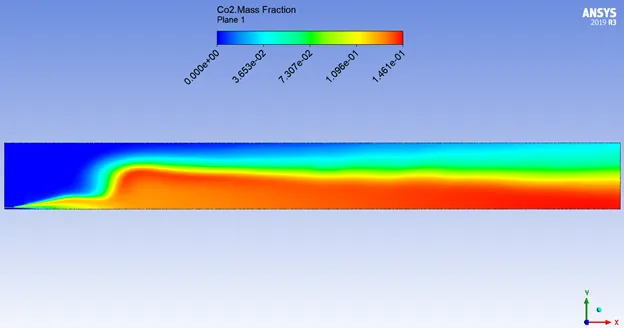
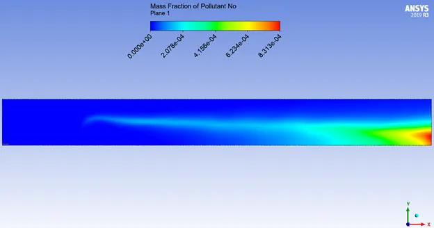
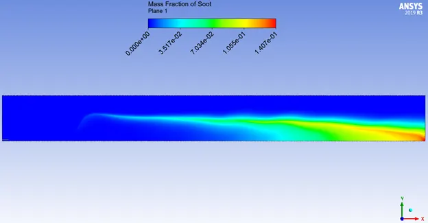
Pollutant Combustion Products Contour:
Variation Plots:
CASE 7 (ADDING WATER CONTENT IN FUEL BY MOLE 30%):
AIR INLET `->` Species `->` Species Mole Fraction `->` O2 = 0.21, CH4 = 0, CO = 0, CO2 = 0, H2O = 0
FUEL INLET `->` Species `->` Species Mole Fraction `->` O2 = 0, CH4 = 0.7, CO2 = 0, CO = 0, H2O = 0.3
Hybrid Initialization
Number of Iterations Given to Run = 1500
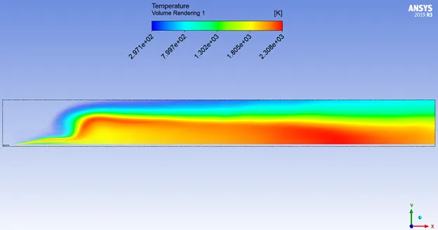
Temperature Volume Render:
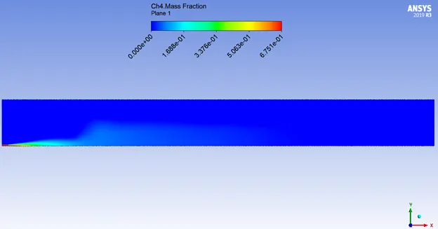
Fuel & Oxidant Contour:
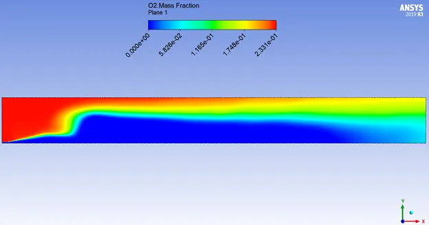
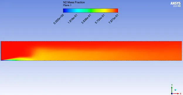
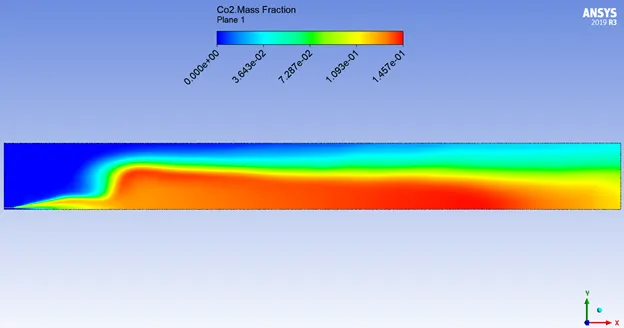
Inert & Non-Pollutant Combustion Products Contour:
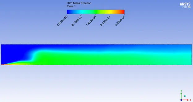
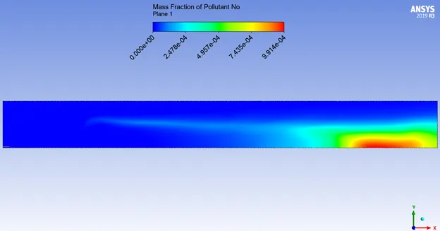
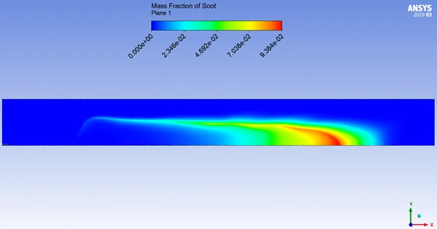
Pollutant Combustion Products Contour:
Variation Plots:
INFERENCE:
The purpose of supplying water:
Minimizing temperature peaks during the combustion process in cylinders, hence NOX concentration in exhaust gas, can be done by means of supplying water into the cylinders (so-called wet technologies). The emulsion supplied into the cylinder causes the increase of self-ignition delay which affects the flammable mixture becoming more homogeneous in the whole volume of the combustion chamber. The increased self-ignition delay extends the time necessary to spread the injected fuel which results in fewer zones with not enough oxygen. That decreases the intensity of soot and CO formation.
Water supplied into the combustion chamber, apart from lowering the combustion temperature also decreases the concentration of atomic oxygen by reaction:
H2O `->` OH + H
H2O + O `->` OH + OH
H2 + O `->` H + OH
H + O2 `->` OH + O
which influences the reaction speed:
O + N2 `->` NO + N
O + N2 + OH `->` N2O + OH
OH formed this way is more difficult to interact with atomic N, which, as a consequence, significantly lowers the amount of NO.
CONCLUSION:
- The levels of oxides of nitrogen (NOX) and soot keeps decreasing as we add more water content in the fuel.
- The effective temperature inside the combustion chamber also decreases as we add more water content to the fuel.
- The most amount of NOX and Soot are formed near the outlet, for simulations with lesser water content in fuel. When the water content was increased to 30% mole percentage in fuel, we can see that the soot and NOX becomes less prominent at the outlet. (The reason explained above)
- Here, Combustion simulation assessed the chemical kinetics of the reactions through the species transport model, which provided in-depth assessment of the entire combustion process through eddy-dissipation.