DESIGN OF A CHECK VALVE
AIM:
Design of a Pneumatic in-line Check Valve with Inlet Día of ∅7 mm and Outlet Día of ∅8 mm using Autodesk Inventor.
CHECK VALVE:
A check valve, clack valve, non-return valve, reflux valve, retention valve or one-way valve is a valve that normally allows fluid (liquid or gas) to flow through it in only one direction. Check valves are two-port valves, meaning they have two openings in the body, one for fluid to enter and the other for fluid to leave. There are various types of check valves used in a wide variety of applications.
This type of check valve is used for aerospace applications.
An important concept in check valves is the cracking pressure which is the minimum differential upstream pressure between inlet and outlet at which the valve will operate. Typically, the check valve is designed for and can therefore be specified for a specific cracking pressure.
Cracking pressure – Refers to the minimum pressure differential needed between the inlet and outlet of the valve at which the first indication of flow occurs (steady stream of bubbles). Cracking pressure is also known as unseating head (pressure) or opening pressure.
Reseal pressure – Refers to the pressure differential between the inlet and outlet of the valve during the closing process of the check valve, at which there is no visible leak rate. Reseal pressure is also known as sealing pressure, seating head (pressure) or closing pressure.
Back pressure – a pressure higher at the outlet of a fitting than that at the inlet or a point upstream.
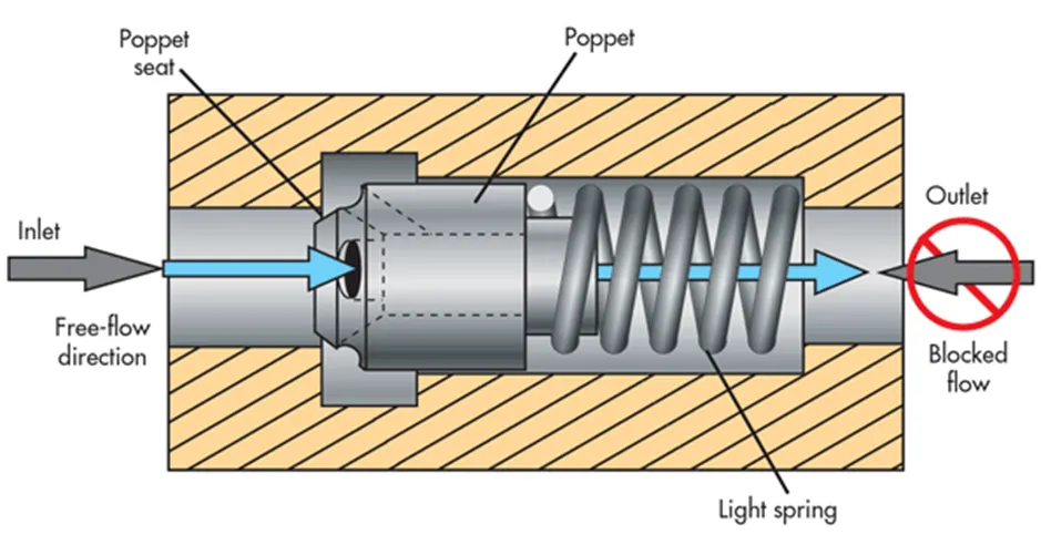
An In-Line Check Valve is a check valve similar to the lift check valve. However, this valve generally has a spring that will 'lift' when there is pressure on the upstream side of the valve. The pressure needed on the upstream side of the valve to overcome the spring tension is called the 'cracking pressure'. When the pressure going through the valve goes below the cracking pressure, the spring will close the valve to prevent back-flow in the process.
IN-LINE CHECK VALVE SCHEMATIC:
COMPONENTS OF IN-LINE CHECK VALVE:
|
PART NO. |
TITLE |
NUMBER |
MATERIAL |
|
1 |
Outlet Adaptor |
1 |
AISI 304L |
|
2 |
Body |
1 |
AISI 304L |
|
3 |
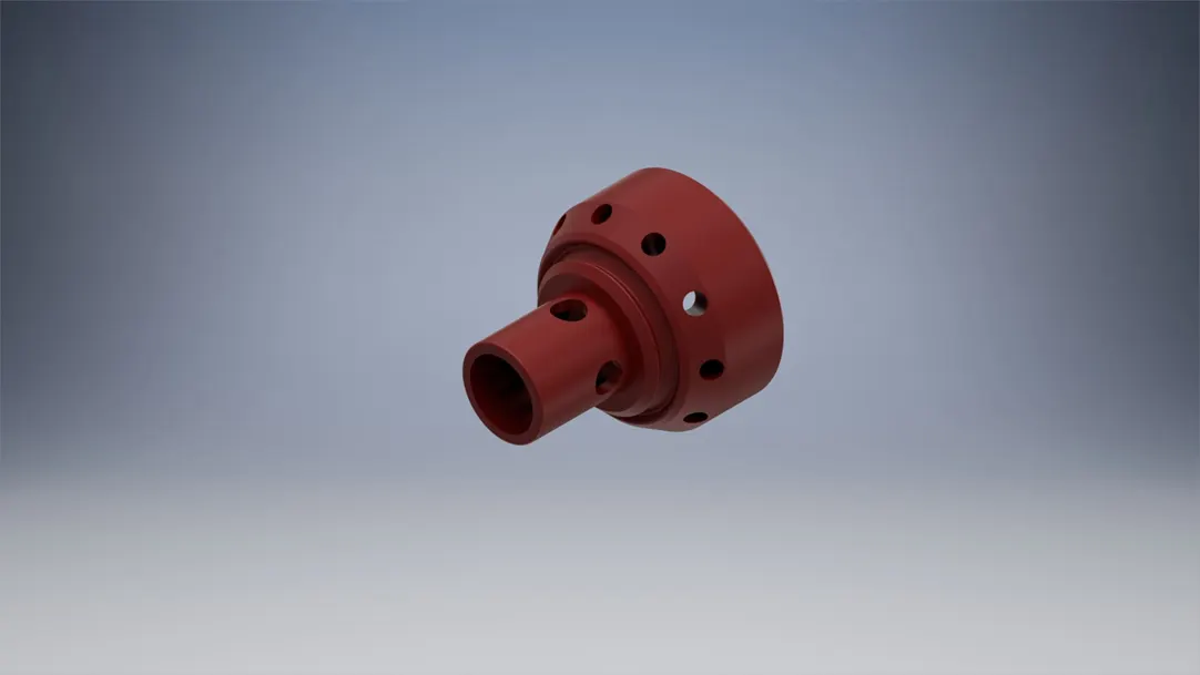
Poppet |
1 |
AISI 304L |
|
4 |
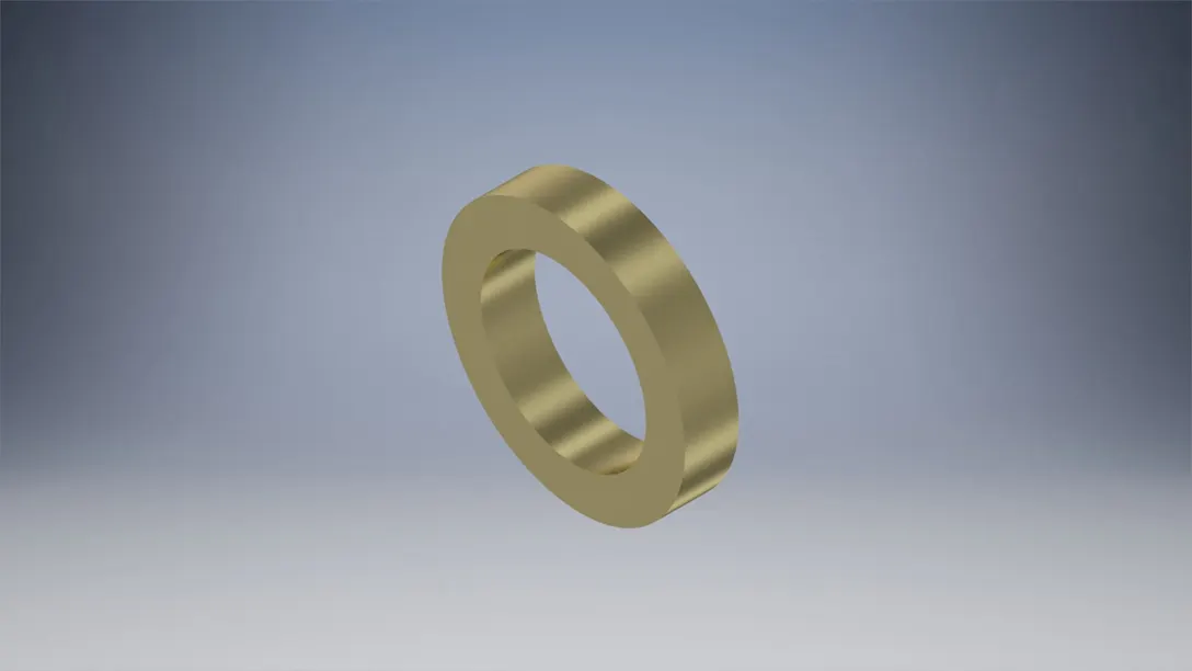
Spring Spacer |
1 |
AISI 304L |
|
5 |
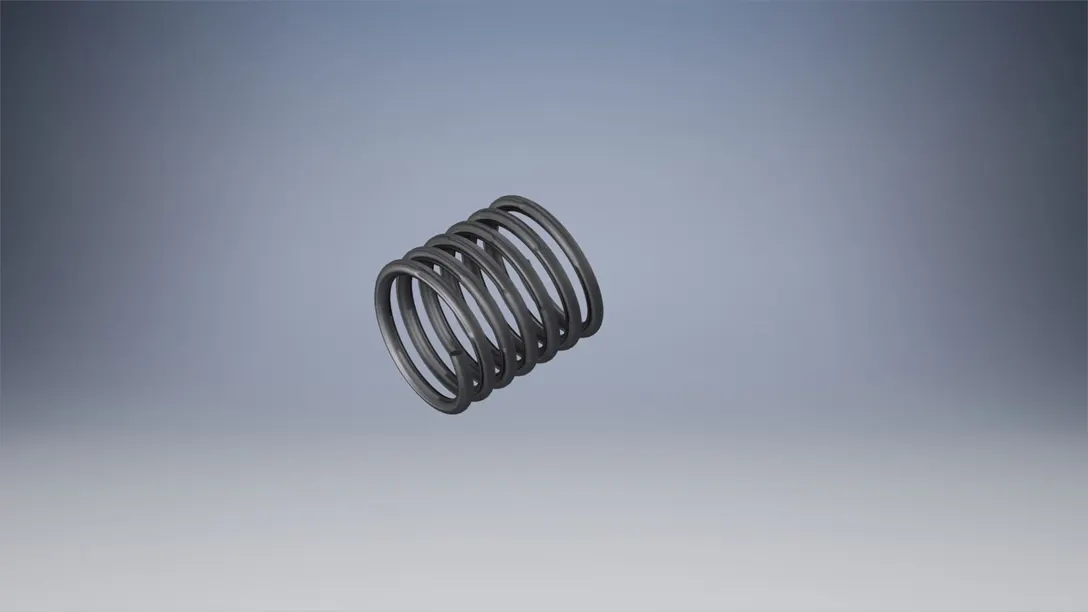
Helical Spring |
1 |
AISI 302 |
|
6 |
`O’ Ring (20.35 ID x 1.78 CS) |
1 |
VITON |
|
7 |
`O’ Ring (13 ID x 16 OD) |
1 |
TEFLON |
|
8 |
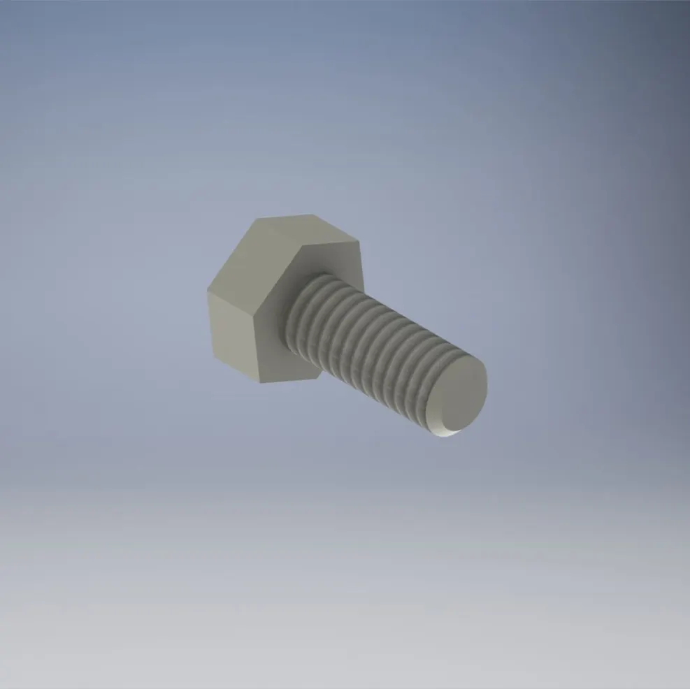
Hex. Socket Head Screw M4 x 0.7 x 12L |
4 |
AISI 431 |
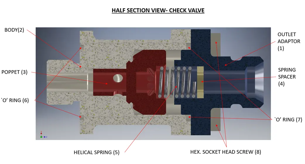
CHECK VALVE COMPONENTS:
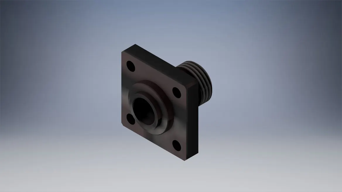
OUTLET ADAPTOR:
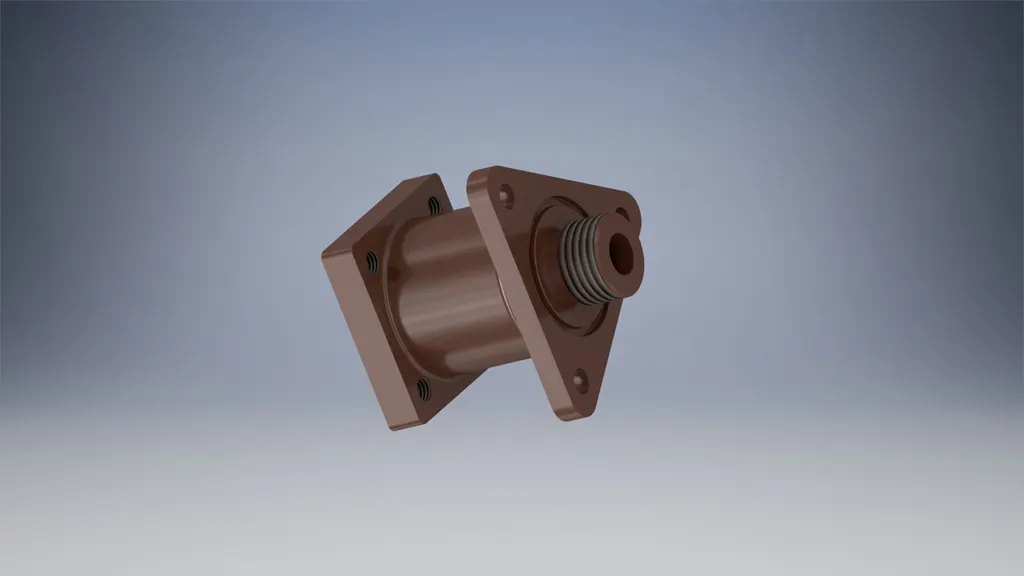
BODY:
POPPET:
SPRING SPACER:
HELICAL SPRING:
HEXAGONAL SOCKET HEAD SCREW:
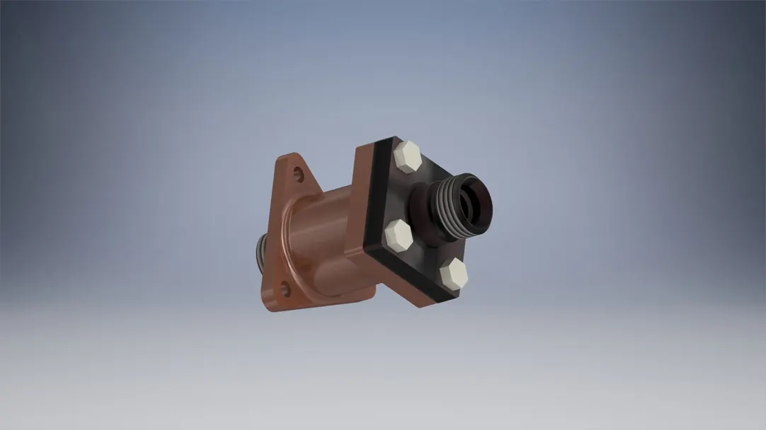
ASSEMBLED IN-LINE CHECK VALVE:
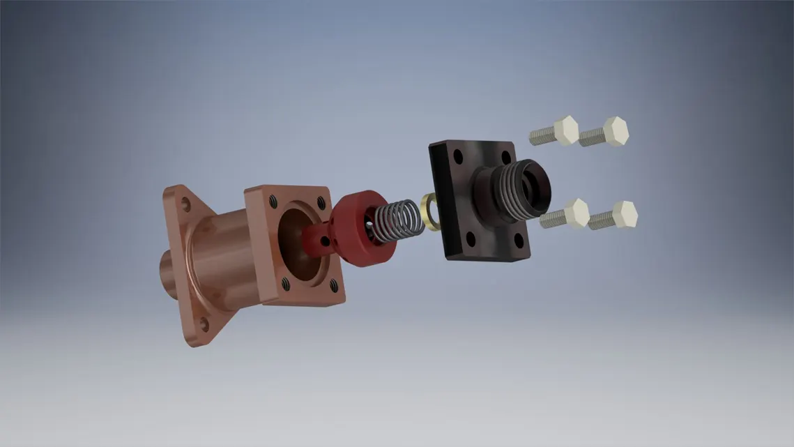
EXPLODED VIEW:
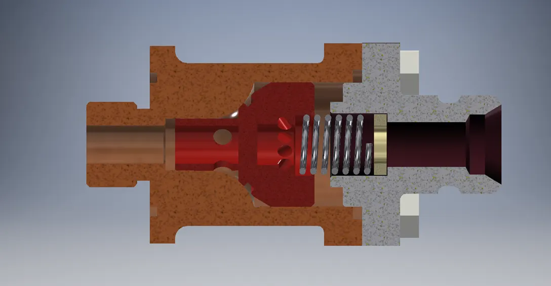
HALF-SECTION VIEW:
CONLUSION:
An In-Line Check Valve was created with an inlet ID of ∅7 mm and Outlet ID of ∅8 mm. Threaded joints were used at both inlet and outlet to fix the fluid lines to the check valve.