NUMERICAL ANALYSIS OF GEARBOX SLOSHING
Performing four simulations in the gearbox with 20% & 30% immersion of gear in fluid (Oil & ATF) (engine oil and n-Heptane) using an UDF.
AIM:
Performing 4 simulations below to determine effective gearbox sloshing.
- 20% Immersion, Fluid: Engine oil
- 30% Immersion, Fluid: Engine oil
- 20% Immersion, Fluid: n-heptane ( C7H16 )
- 30% Immersion, Fluid: n-heptane ( C7H16 )
OBJECTIVE:
To determine if a gearbox lubricant is adequately reaching all the gear (Spur Gear: 0.5 mm clearance) teeth for effective gearbox sloshing.
FLUID SLOSHING EFFECT:
In fluid dynamics, slosh refers to the movement of liquid inside another object (which is, typically, also undergoing motion). The liquid must also have a free surface to constitute a slosh dynamics problem, where the dynamics of the liquid can interact with the container to alter the system dynamics significantly.
Important examples include propellant slosh in spacecraft tanks and rockets (especially upper stages), and the free surface effect (cargo slosh) in ships and trucks transporting liquids (for example oil and gasoline). However, it has become common to refer to liquid motion in a completely filled tank, i.e. without a free surface, as "fuel slosh".
Such motion is characterized by "inertial waves" and can be an important effect in spinning spacecraft dynamics. Extensive mathematical and empirical relationships have been derived to describe liquid slosh. These types of analyses are typically undertaken using computational fluid dynamics and finite element methods to solve the fluid-structure interaction problem, especially if the solid container is flexible. Relevant fluid dynamics non-dimensional parameters include the Bond number, the Weber number, and the Reynolds number.
The fluid sloshing effect is advantageous based on the scenarios where it occurs.
- Sloshing or shifting cargo, water ballast, or other liquid (e.g., from leaks or fire fighting) can cause disastrous capsizing in ships due to free surface effect; this can also affect trucks and aircraft.
- The effect of slosh is used to limit the bounce of a roller hockey ball. Water slosh can significantly reduce the rebound height of a ball but some amounts of liquid seem to lead to a resonance effect. Many of the balls for roller hockey commonly available contain water to reduce the bounce height.
- Liquid sloshing strongly influences the directional dynamics and safety performance of highway tank vehicles in a highly adverse manner. Hydrodynamic forces and moments arising from liquid cargo oscillations in the tank under steering and/or braking maneuvers reduce the stability limit and controllability of partially-filled tank vehicles. Anti-slosh devices such as baffles are widely used in order to limit the adverse liquid slosh effect on directional performance and stability of the tank vehicles.
In this case of gearbox sloshing its actually quite advantageous.
- If the fluid is ATF (Automatic Transmission Fluid), it is a complex fluid full of lubricants and detergents that keep the transmission running smoothly with minimal wear. ATF also works as a hydraulic fluid for power steering systems and some 4WD cases in automatic cars. It also contains a combination of additives including anti-wear additives, additives that block rust and corrosion, dispersants and surfactants that protect and clean metal parts in a transmission, kinematic viscosity and viscosity index improvers, seal swell additives that increase rotational speed and temperature range, anti-foam additives, anti-oxidation compounds, cold-flow improvers, high-temperature thickeners, gasket conditioners, pour point depressant, and some form of petroleum dye.
- If the fluid is Gear oil, it works to lubricate and prevent corrosion in a manual transmission. Because manual transmissions experience high friction during gear changes and clutch press-and-release, gear oil has additives of sulfur-bearing anti-wear compounds. This gives gear oil a distinctive, strong smell. Gear oil is also thicker than ATF because it serves mainly to lubricate the gearbox, transfer cases, and differentials.
For this type analysis a Dynamic Mesh will be used.
The dynamic mesh model allows you to move the boundaries of a cell zone relative to other boundaries of the zone, and to adjust the mesh accordingly. The boundaries can move rigidly with respect to each other (that is, linear or rotational motion), and/or deform. The motion of the boundaries can be rigid.
Examples:Water wheel, dropping of a ball into a water container case, Pistons moving inside an engine cylinder or a flap deflecting on an aircraft wing, or deforming, such as the elastic wall of a balloon during inflation or a flexible artery wall responding to the pressure pulse from the heart. In either case, the nodes that define the cells in the domain must be updated as a function of time, and hence the dynamic mesh solutions are inherently unsteady.
For this type analysis an UDF (USER DEFINED FUNCTION) will also be used.
An user-defined function, or UDF, is a function that you program that can be dynamically loaded with the ANSYS FLUENT solver to enhance the standard features of the code. For example, you can use a UDF to define your own boundary conditions, material properties, and source terms for your flow regime, as well as specify customized model parameters (e.g., DPM, multiphase models), initialize a solution, or enhance postprocessing. UDFs are written in the C programming language using any text editor and the source code file is saved with a '.c' extension (e.g., myudf.c). One source file can contain a single UDF or multiple UDFs, and you can define multiple source files.
MODEL AND FLOW DOMAIN:
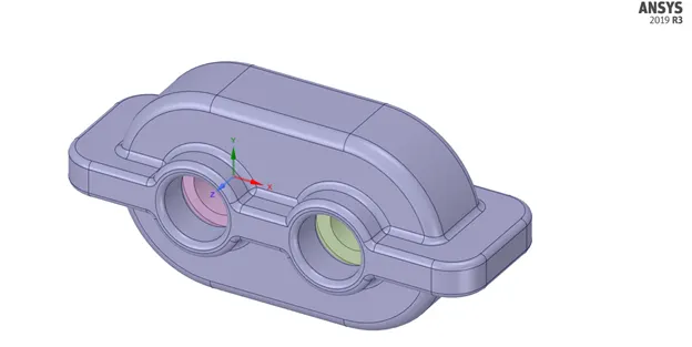
SPUR GEAR: 0.5 MM CLEARANCE (Fluid volume prepared by Volume extract):
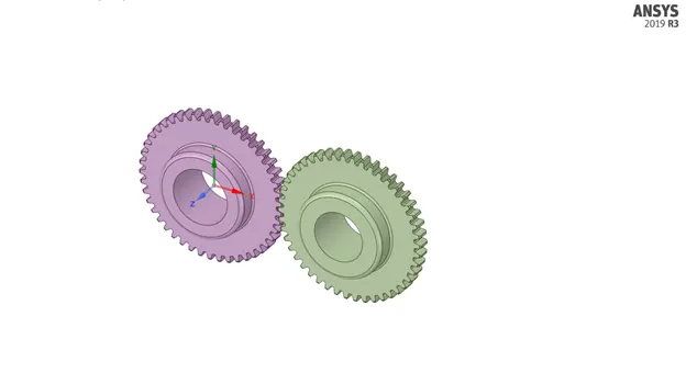
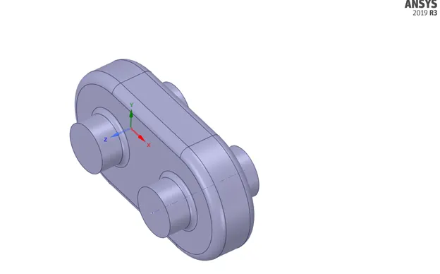
2D FLOW DOMAIN:
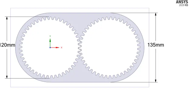
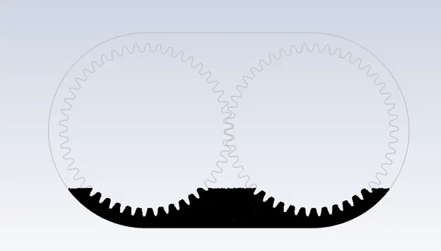
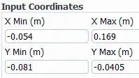
20 % Immersion `->` `135 * 0.2` = 27 mm, Fluid Level from Bottom
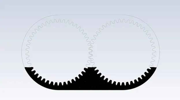
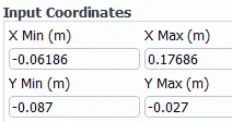
30 % Immersion `->` `135 * 0.3` = 40.5 mm, Fluid Level from Bottom
FLUID REGION:
20 % GEAR IMMERSION:
30 % GEAR IMMERSION:
BOUNDARIES:
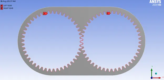
MESH:
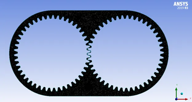


Mesh Method `->`Triangles
Capture Proximity `->` Yes
Number of Cells across Gap `->` 3
TRANSIENT SIMULATION SETUP:
Pressure-Based Simulation
Gravity enabled `->` y = -9.81 m/s
K-epsilon Realizable model with enhanced wall treatment.
UDF (User Defined Function):
#include "udf.h"

DEFINE_CG_MOTION(right_motion, dt, vel, omega, time, dtime)
{
	vel[0] = 0.0;
	vel[1] = 0.0;
	vel[2] = 0.0;

	omega[0] = 0.0;
	omega[1] = 0.0;
	omega[2] = 2.0e2; /* [rad/s]*/
}
DEFINE_CG_MOTION(left_motion, dt, vel, omega, time, dtime)
{
	vel[0] = 0.0;
	vel[1] = 0.0;
	vel[2] = 0.0;

	omega[0] = 0.0;
	omega[1] = 0.0;
	omega[2] = -2.0e2; /* [rad/s]*/
}
The above UDF `->` Added `->` Built `->` Loaded
Here, w = `(2⋅π⋅N)/60` = 200 rad/s
N = `(200⋅60)/(2⋅π)`= 1909.859 rpm = 31.8309 rps
DYNAMIC MESH `->` Enabled
Mesh Methods Enabled:
- Smoothing
- Layering
- Remeshing
Remeshing Methods `->` Local Cell (Parameters Below)
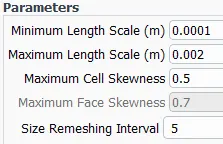
DYNAMIC MESH ZONES `->` Created
TYPE `->` Rigid Body
LEFT GEAR `->` left_motion::libudf (From UDF) `->` Center of Gravity (0. m, 0 m)
RIGHT GEAR `->` right_motion::libudf (From UDF) `->` Center of Gravity (0.115 m, 0 m)
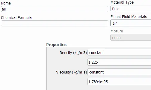
SIMULATION WITH ENGINE OIL:
MULTIPHASE MODEL `->` Volume of Fluid `->` Implicit Formulation
Primary Phase `->` Air
Secondary Phase `->` Engine Oil
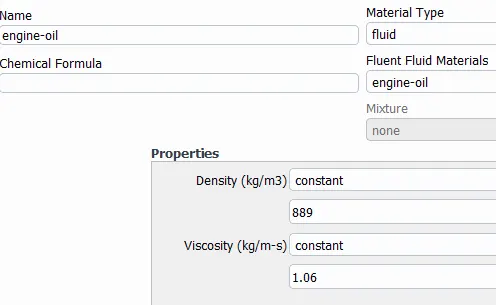
Hybrid Initialization
Secondary Phase patched to the region marked
Time Step Size (s) `->` 0.0001
Number of Time Steps `->` 10000
20 % IMMERSION

For this flow time, Number of Rotations achieved = `31.8309⋅0.5628999` = 17.91766 Gear Rotations
30 % IMMERSION

For this flow time, Number of Rotations achieved = `31.8309⋅0.99999` = 31.83058 Gear Rotations
SIMULATION WITH n-HEPTANE (C7H16) - LIQUID:
MULTIPHASE MODEL `->` Volume of Fluid `->` Implicit Formulation
Primary Phase `->` Air
Secondary Phase `->` n-Heptane (C7H16) (Liquid)
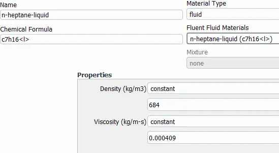
Hybrid Initialization
Secondary Phase patched to the region marked
Time Step Size (s) `->` 0.0001
Number of Time Steps `->` 10000
20 % IMMERSION

For this flow time, Number of Rotations achieved = `31.8309⋅0.40189999` = 12.79283 Gear Rotations
30 % IMMERSION

For this flow time, Number of Rotations achieved = `31.8309⋅0.6523999` = 20.76644 Gear Rotations
INFERENCE:
For all four smulations conducted each one of them achieved varrying number of rotations. But, none of the simulations has number of rotations less than 7 and can be used for extracting data regarding effective gearbox sloshing. The reason for not achieveing a flow time 1 second is due to the occurance of errors such as:
- 'Dynamic mesh failed'
- 'Negative cell volume detected'
When the boundary displacement is large compared to local cell size, the cell quality can deteriorate or the cells can become degenerate if only mesh smoothing is used. Ths will invaldate the mesh resulting in the error 'negative cell volume detected' and will lead to convergence problems when the solution is updated to the next time step. To circumvent this problem, ANSYS Fluent agglomerates cells that violate the skewness or size criteria and locally remeshes the agglomerated cells or faces. If the new cells or faces satisfy the skewness criterion, the mesh is locally updated with the new cells (with the solution interpolated from the old cells). Otherwise, the new cells are discarded and the old cells are retained.
CONCLUSION:
Based on immersion:
It is observed that 30% immersion is better than 20% immersion for adequeatly distributing gearbox lubricant to the gear teeth for optimum perfomannce.
Based on Gearbox Fluid:
It is observed that n-heptane (liquid) is better than Engine Oil for dequeatly distributing gearbox lubricant to the gear teeth for optimum perfomannce, even at 20 % immersion n-heptane is better than engine oil.
30% immersion n-heptane (liquid) is observerd to have the most effective gearbox sloshing amoung all these four cases.