PARAMETRIC STUDY OF GATE VALVE
AIM:
Parametric study on the gate valve simulation by setting the opening from 10 % to 80% of gate valve.
OBJECTIVE:
- Obtaining the mass flow rates at the outlet for each design point.
- Calculating the flow coefficient and flow factor for each opening and plotting the graph.
GATE VALVE:
A gate valve, also known as a sluice valve, is a valve that opens by lifting a barrier (gate) out of the path of the fluid. Gate valves require very little space along the pipe axis and hardly restrict the flow of fluid when the gate is fully opened. The gate faces can be parallel (used in this simulation) but are most commonly wedge-shaped (in order to be able to apply pressure on the sealing surface).
Gate valves are used to shut off the flow of liquids rather than for flow regulation. When fully open, the typical gate valve has no obstruction in the flow path, resulting in very low flow resistance. The size of the open flow path generally varies in a nonlinear manner as the gate is moved. This means that the flow rate does not change evenly with stem travel. Depending on the construction, a partially open gate can vibrate from the fluid flow.
Gate valves without an extra sealing ring on the gate or the seat are used in applications where minor leaking of the valve is not an issue, such as heating circuits or sewer pipes.
Gate valves are typically constructed from cast iron, cast carbon steel, ductile iron, gunmetal, stainless steel, alloy steels, and forged steels.
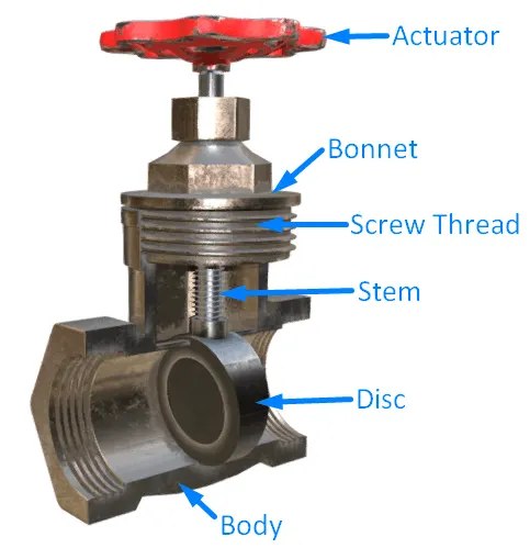
Bonnets provide leakproof closure for the valve body. Gate valves may have a screw-in, union, or bolted bonnet. A screw-in bonnet is the simplest, offering a durable, pressure-tight seal. A union bonnet is suitable for applications requiring frequent inspection and cleaning. It also gives the body added strength. A bolted bonnet is used for larger valves and higher-pressure applications.
FLOW COEFFICIENT:
The flow coefficient of a device is a relative measure of its efficiency at allowing fluid flow. It describes the relationship between the pressure drop across an orifice valve or other assembly and the corresponding flow rate.
Mathematically the flow coefficient CV (or flow-capacity rating of valve) can be expressed as:
CV = `Q*sqrt((SG)/(△P))`
where,
Q is the rate of flow (expressed in US gallons per minute),
SG is the specific gravity of the fluid (for water = 1),
ΔP is the pressure drop across the valve (expressed in psi).
In more practical terms, the flow coefficient Cv is the volume (in US gallons) of water at 60 °F that will flow per minute through a valve with a pressure drop of 1 psi across the valve.
FLOW FACTOR:
The metric equivalent flow factor (KV; commonly used in Europe and Asia) is calculated using metric units:
KV = `Q*sqrt((SG)/(△P))`
Where,
Kv is the flow factor (expressed in m3.h-1.bar-0.5)
Q is the flowrate (expressed in cubic metres per hour m3/h)
SG is the specific gravity of the fluid (for water = 1),
∆P is the differential pressure across the device (expressed in [bar]).
Cv can be calculated from Kv using the equation:
CV = 1.156 × KV
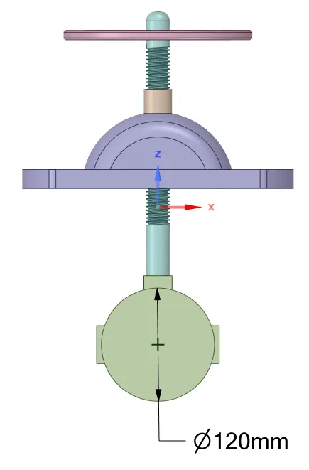
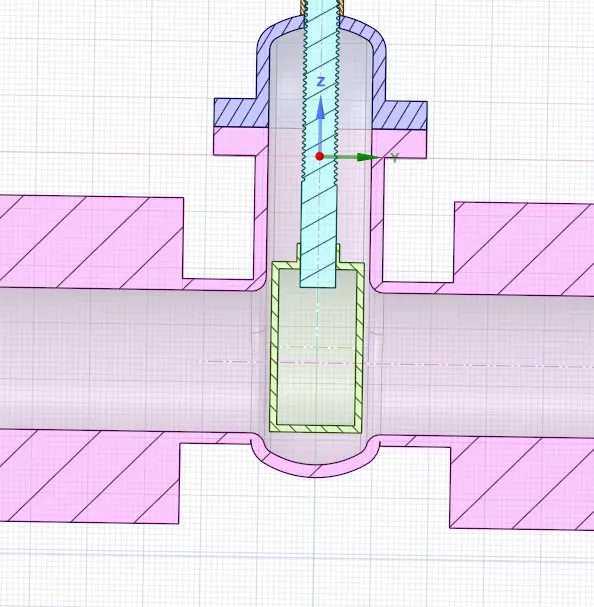
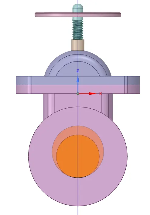
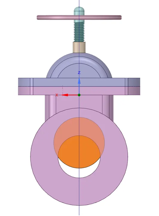
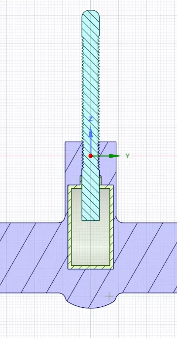
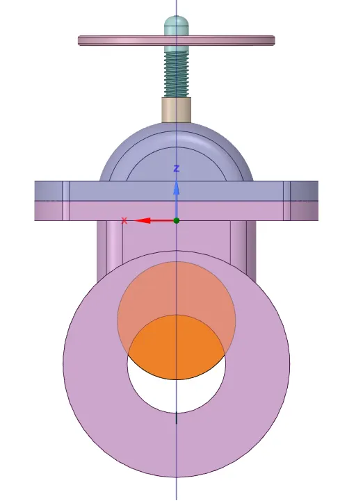
MODEL 4" GATE VALVE:
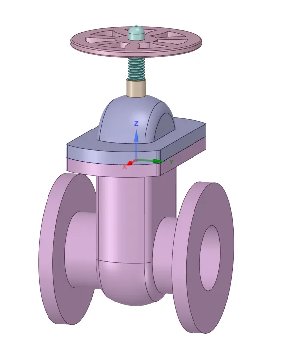
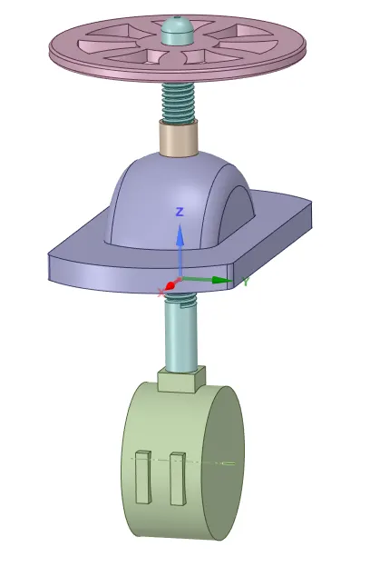
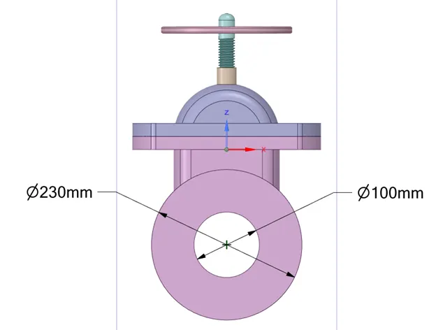
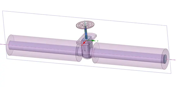
FLOW DOMAIN:
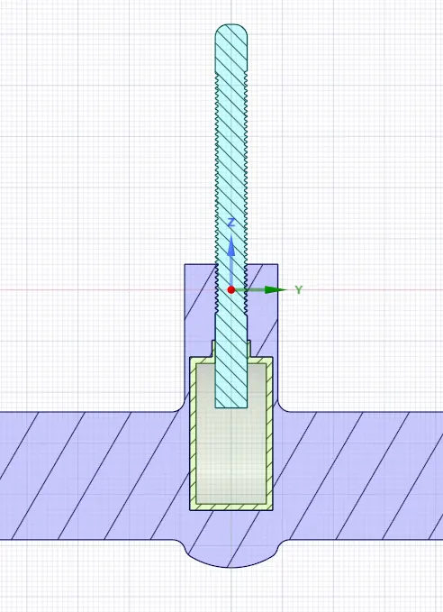
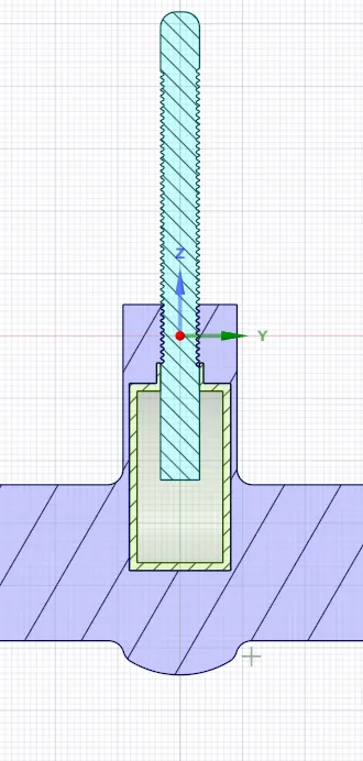
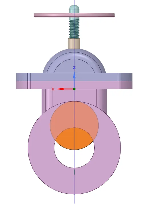
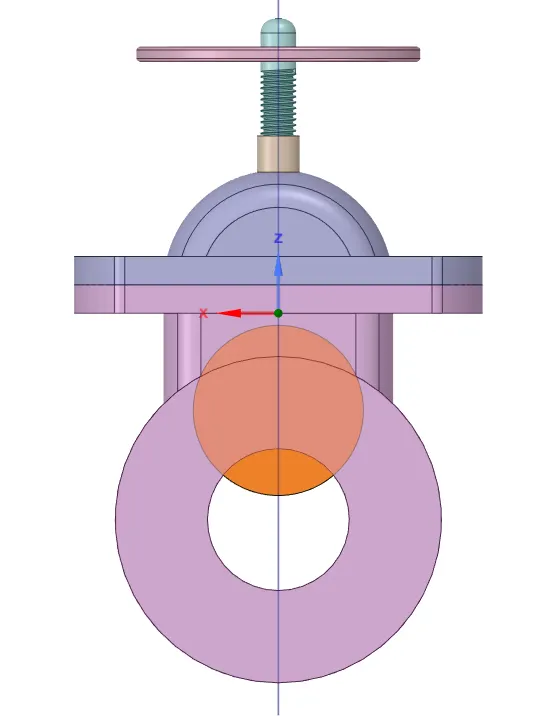
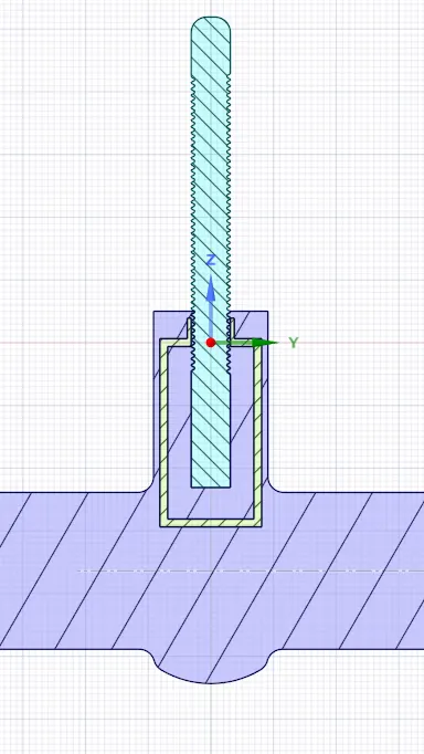
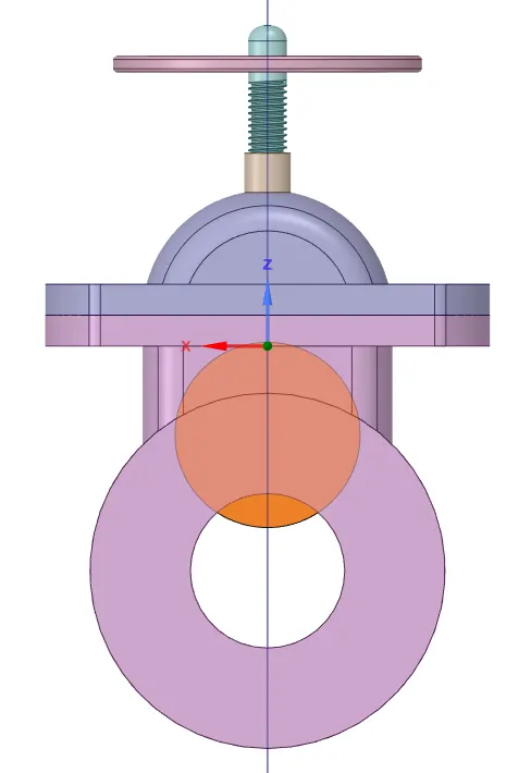
Maximum Possible lift of the Gate Disc
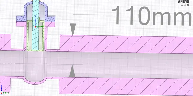
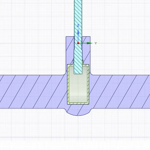
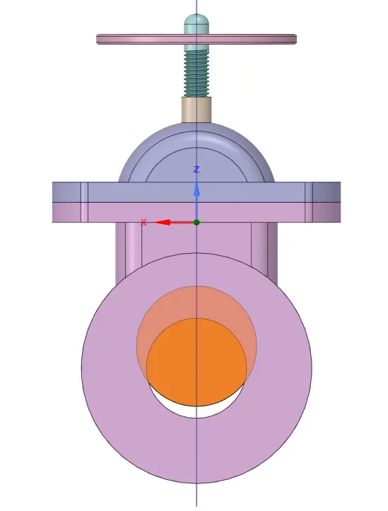
The gate disc lift value is set as a parameter (GROUP 1)
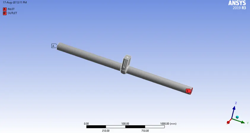
BOUNDARIES:
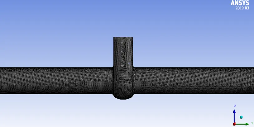
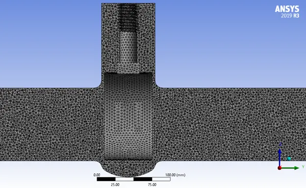
MESH:
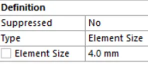
Body sizing applied for a finer mesh on the fluid volume.

STEADT-STATE SIMULATION SETUP:
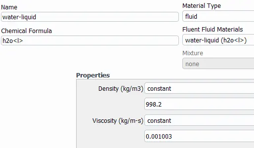
Fluid Material (Inside Gate valve; Fluid Volume) -> Water Liquid (Properties Below)
Red = `(ρ×V×D)/(µ)`
ρ `->` Density of Water = 998.2 kg/m3
D `->` Diameter of the pipe at inlet or outlet = 100 mm = 0.1 m
V `->` Velocity of fluid = 0.1415488 m/s
µ `->` Viscosity of water = 0.001003 kg/m-s
Red = `(998.2×0.1415488×0.1)/(0.001003)` = 14087.139
Red > 2500, Hence the flow is turbulent. So, K-epsilon Realizable Model with scalable wall functions.
Pressure-Based Solver
Pressure-Velocity Coupling `->` Coupled
Spatial Discretization
Pressure `->` Second Order
Momentum `->` Second Order Upwind
Flux Report `->` Mass Flow Rate `->` OUTLET `->` Creating an Output Parameter
BOUNDARY CONDITIONS:
INLET `->` Pressure (Gauge) = 10 Pa
OUTLET `->` Pressure (Gauge) = 0 Pa
Standard Initialization from INLET
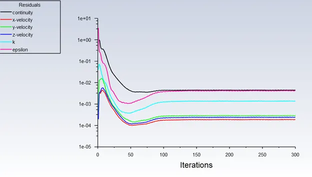
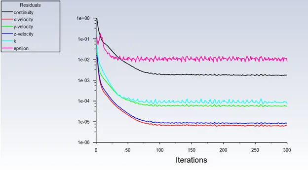
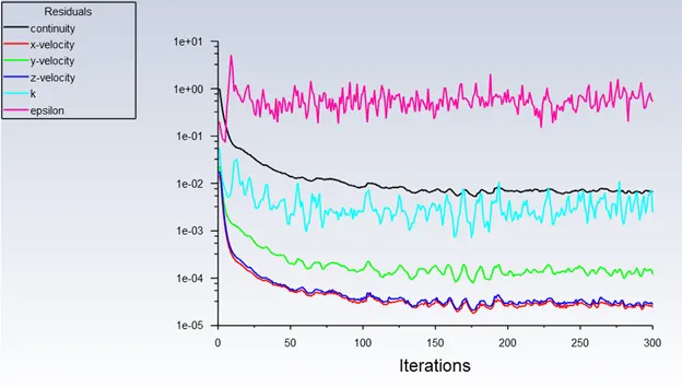
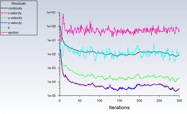
Number of Iterations Given to Run = 300
OBSERVATIONS OF PARAMETRIC SIMULATIONS:
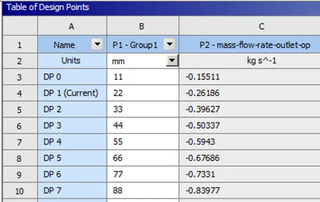
10% RISE OF GATE DISC = 11 mm
△P `->` Pressure Difference = 10 - 0 = 10 Pa = 10-4 Bar
SG `->` Specific Gravity of the Fluid (SGWater = 1)
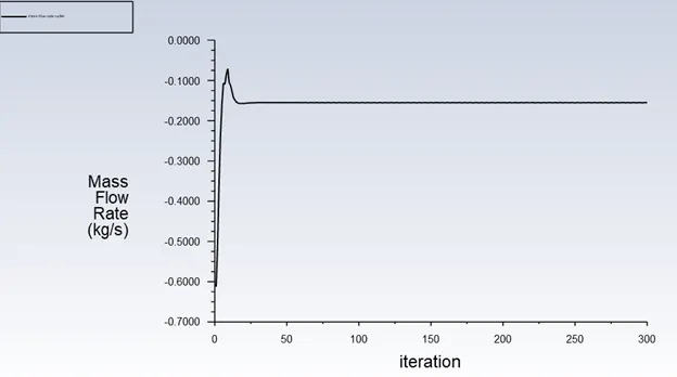
Q `->` Flowrate = -0.15511 kg/s (-ve sign indicates fluid flows out of volume) = 0.558396 m3/h
KV = `Q*sqrt((SG)/(△P))` = `Q*sqrt(1/10^-4)` = `100*Q` = `100*0.558396`
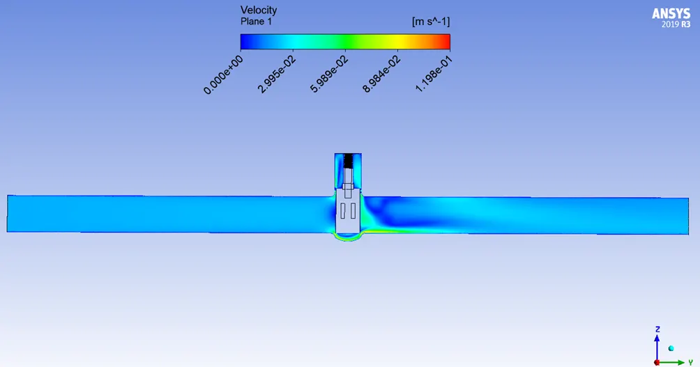
KV = 55.8396 m3.h-1.bar-0.5
CV = 1.156 × KV = `1.156*55.8396` = 64.550776 GPM.Psi-0.5
20% RISE OF GATE DISC = 22 mm
△P `->` Pressure Difference = 10 - 0 = 10 Pa = 10-4 Bar
SG `->` Specific Gravity of the Fluid (SGWater = 1)
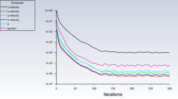
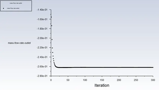
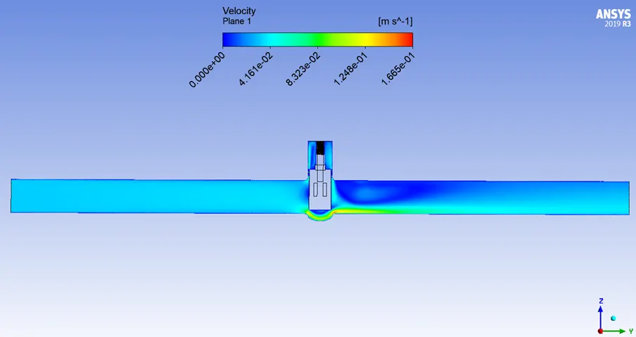
Q `->` Flowrate = -0.26186 kg/s (-ve sign indicates fluid flows out of volume) = 0.942696 m3/h
KV = `Q*sqrt((SG)/(△P))` = `Q*sqrt(1/10^-4)` = `100*Q` = `100*0.942696`
KV = 94.2696 m3.h-1.bar-0.5
CV = 1.156 × KV = `1.156*94.2696` = 108.9756576 GPM.Psi-0.5
30% RISE OF GATE DISC = 33 mm
△P `->` Pressure Difference = 10 - 0 = 10 Pa = 10-4 Bar
SG `->` Specific Gravity of the Fluid (SGWater = 1)
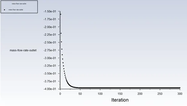
Q `->` Flowrate = -0.39627 kg/s (-ve sign indicates fluid flows out of volume) = 1.426572 m3/h
KV = `Q*sqrt((SG)/(△P))` = `Q*sqrt(1/10^-4)` = `100*Q` = `100*1.426572`
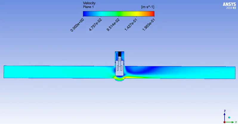
KV = 142.6572 m3.h-1.bar-0.5
CV = 1.156 × KV = `1.156*142.6572` = 164.9117232 GPM.Psi-0.5
40% RISE OF GATE DISC = 44 mm
△P `->` Pressure Difference = 10 - 0 = 10 Pa = 10-4 Bar
SG `->` Specific Gravity of the Fluid (SGWater = 1)
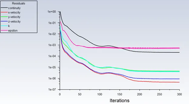
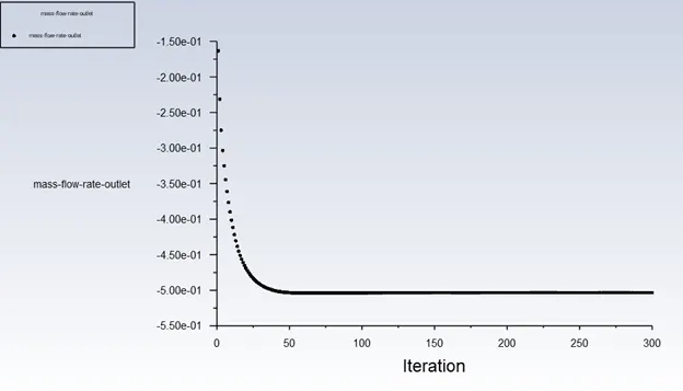
Q `->` Flowrate = -0.50337 kg/s (-ve sign indicates fluid flows out of volume) = 1.812132 m3/h
KV = `Q*sqrt((SG)/(△P))` = `Q*sqrt(1/10^-4)` = `100*Q` = `100*1.812132`
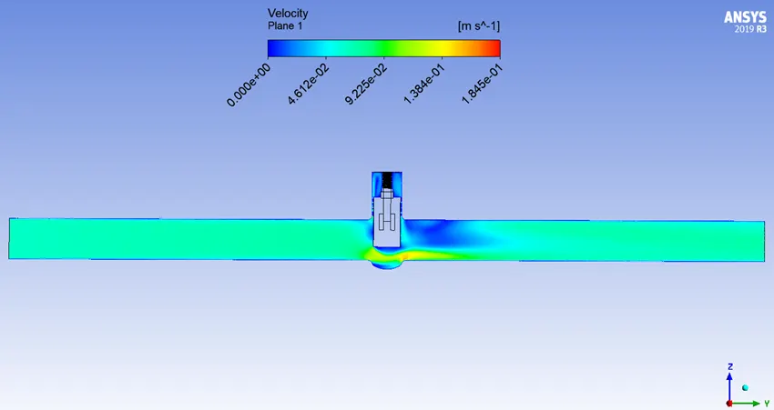
KV = 181.2132 m3.h-1.bar-0.5
CV = 1.156 × KV = `1.156*181.2132` = 209.4824592 GPM.Psi-0.5
50% RISE OF GATE DISC = 55 mm
△P `->` Pressure Difference = 10 - 0 = 10 Pa = 10-4 Bar
SG `->` Specific Gravity of the Fluid (SGWater = 1)
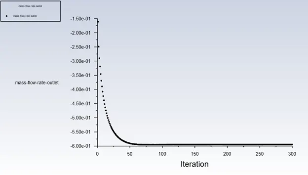
Q `->` Flowrate = -0.5943 kg/s (-ve sign indicates fluid flows out of volume) = 2.139480 m3/h
KV = `Q*sqrt((SG)/(△P))` = `Q*sqrt(1/10^-4)` = `100*Q` = `100*2.139480`
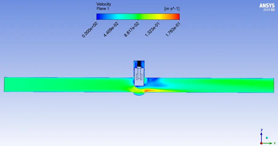
KV = 213.9480 m3.h-1.bar-0.5
CV = 1.156 × KV = `1.156*213.9480` = 247.323888 GPM.Psi-0.5
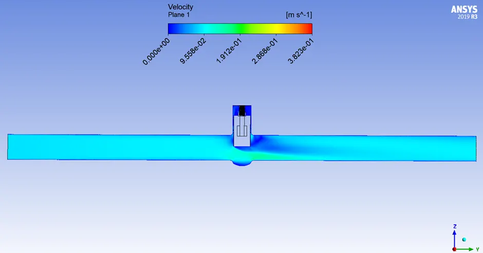
60% RISE OF GATE DISC = 66 mm
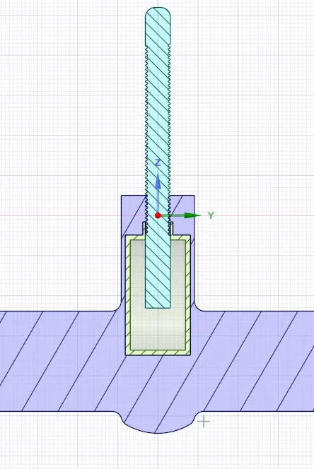
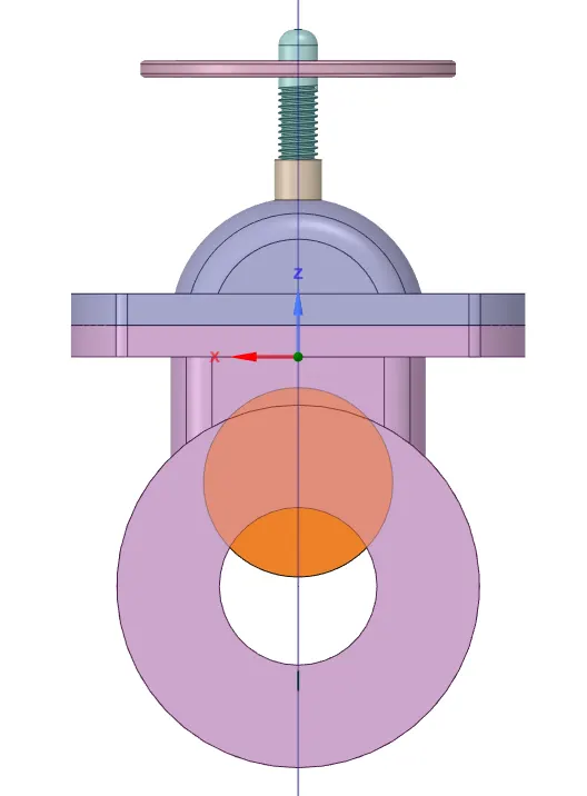
△P `->` Pressure Difference = 10 - 0 = 10 Pa = 10-4 Bar
SG `->` Specific Gravity of the Fluid (SGWater = 1)
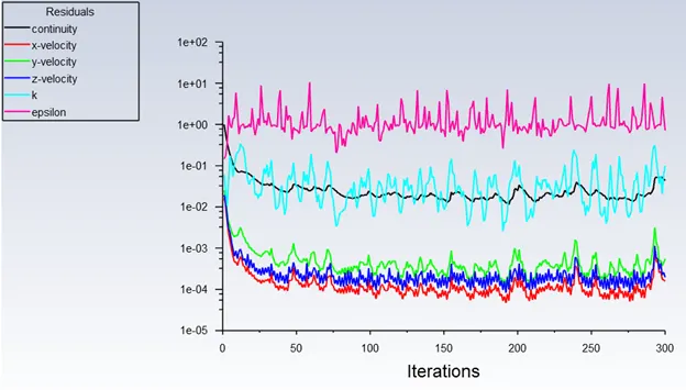
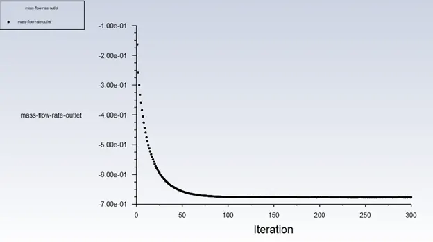
Q `->` Flowrate = -0.67686 kg/s (-ve sign indicates fluid flows out of volume) = 2.436696 m3/h
KV = `Q*sqrt((SG)/(△P))` = `Q*sqrt(1/10^-4)` = `100*Q` = `100*2.436696`
KV = 243.6696 m3.h-1.bar-0.5
CV = 1.156 × KV = `1.156*243.6696` = 281.6820576 GPM.Psi-0.5
70% RISE OF GATE DISC = 77 mm
△P `->` Pressure Difference = 10 - 0 = 10 Pa = 10-4 Bar
SG `->` Specific Gravity of the Fluid (SGWater = 1)
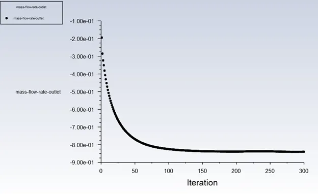
Q `->` Flowrate = -0.7331 kg/s (-ve sign indicates fluid flows out of volume) = 2.639160 m3/h
KV = `Q*sqrt((SG)/(△P))` = `Q*sqrt(1/10^-4)` = `100*Q` = `100*2.639160`
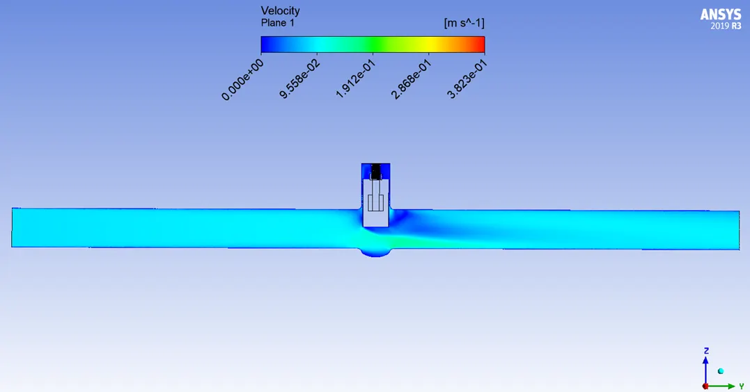
KV = 263.9160 m3.h-1.bar-0.5
CV = 1.156 × KV = `1.156*263.9160` = 305.086896 GPM.Psi-0.5
80% RISE OF GATE DISC = 88 mm
△P `->` Pressure Difference = 10 - 0 = 10 Pa = 10-4 Bar
SG `->` Specific Gravity of the Fluid (SGWater = 1)
Q `->` Flowrate = -0.83977 kg/s (-ve sign indicates fluid flows out of volume) = 3.023172 m3/h
KV = `Q*sqrt((SG)/(△P))` = `Q*sqrt(1/10^-4)` = `100*Q` = `100*3.023172`
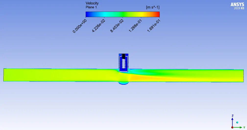
KV = 302.3172 m3.h-1.bar-0.5
CV = 1.156 × KV = `1.156*302.3172` = 349.4786832 GPM.Psi-0.5
OBSERVATIONS:
|
Rise of Gate Disc (%) |
Rise of Gate Disc (mm) |
Pressure Difference (Inlet – Outlet) (Pa) |
Mass Flow Rate at Outlet (kg/s) |
Flow Coefficient, CV (GPM.Psi-0.5) |
Flow Factor, KV (m3.h-1.bar-0.5) |
|
10 |
11 |
10 |
0.15511 |
64.550776 |
55.8396 |
|
20 |
22 |
10 |
0.26186 |
108.975657622 |
94.2696 |
|
30 |
33 |
10 |
0.39627 |
164.9117232 |
142.6572 |
|
40 |
44 |
10 |
0.50337 |
209.482459244 |
181.2132 |
|
50 |
55 |
10 |
0.5943 |
247.323888 |
213.9480 |
|
60 |
66 |
10 |
0.67686 |
281.6820576 |
243.6696 |
|
70 |
77 |
10 |
0.7331 |
305.086896 |
263.9160 |
|
80 |
88 |
10 |
0.83977 |
349.4786832 |
302.3172 |
INFERENCE:
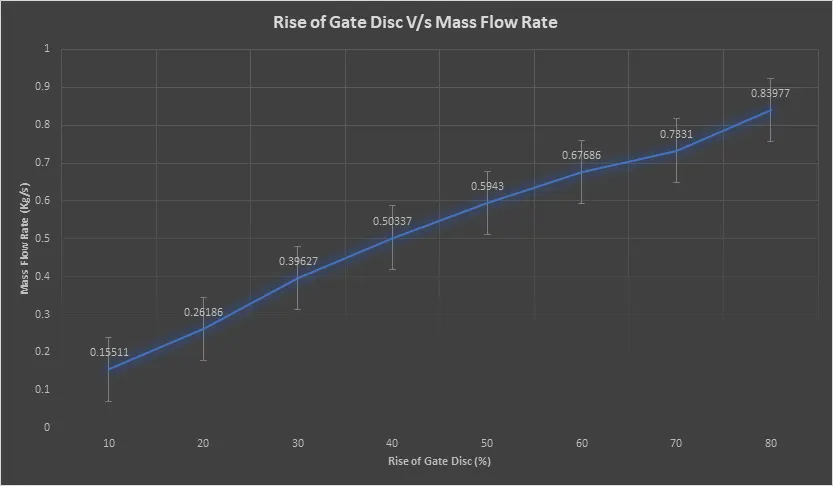
Mass flow rate increases as the gate disc rises.
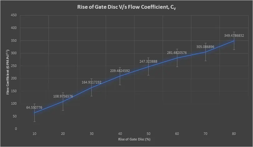
Flow coefficient increases as the gate disc rises.
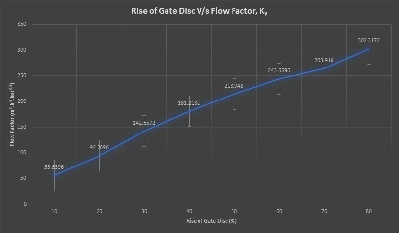
Flow factor increases as the gate disc rises.
CONCLUSION:
- Mass flow rate at the outlet, flow coeffiicient and flow factor increases with the opening of the gate valve from 10% to 80%.
- This increase in mass flow rate at outlet, flow coefficient and flow factor are gradual and the varration is proportional.
- The variation of mass flow rate at outlet, flow coeffcient and flow factor are linear with respect to the gate valve opening, with the varration from 70% to 80% is more signficant than the rest.
- For selecting a gate valve based on calculated values of Flow coefficient (CV) or Flow factor (KV), the value should lie between 20% and 80% gate valve opening. Here, this gate valve (100 mm or 4 inch) is optimum for conditions with CV ranging from 108.975 to 349.478 and (KV) ranging from 94.26 to 302.31.