Section Modulus calculation and optimization
Aim:
The main objective of this project is to understand and learn the basic tools and advanced tools used in NX and calculation as well as section modulus and optimization of Car Hood and calculate the Section Modulus and optimization using the formula.
SECTION MODULUS:
Section modulus is a geometric property for a given cross-section used in the design of beams or flexural members Other geometric properties used in the design include an area for tension and shear, the redius of gyration for compression, and the moment of inertia and polar momemt of inertia for stiffness. Any relationship between these properties is highly dependent on the shape in question.Equations for the section modulus is common shapes are given below. There are two types of section modulus, the elastic section modulus, and the plastic section modulus. The section moduli of different profiles can also be found as numerical values for common profiles in tables listing properties of such.
Use the Section from your Hood design and calculate the section modulus using the formula S = I/y
S = Section Modulus
I = Moment of Inertia
y = distance between the neutral axis and the extreme end of the object
Come up with a new section that has improved the section modulus of the previous section and mention what change you made that has increased the strength.
Elastic section modulus:
For general design, the elastic section modulus is used, applicable up to the yield point for most metals and other common materials.
The elastic section modulus is defined as S = I / y, where I is the second moment of inertia (or area moment of inertia, not to be confused with moment of inertia) and y is the distance from the neutral axis to any given fibre. It is often reported using y = c, where c is the distance from the neutral axis to the most extreme fibre, as seen in the table below. It is also often used to determine the yield moment (My) such that My = S ⋅ σy, where σy is the yield strength of the material.
| Cross-sectional shape | Figure | Equation | Comment |
|---|---|---|---|
| Rectangle |  |
Solid arrow represents neutral axis | |
| doubly symmetric I-section (major axis) | 
|
NA indicates neutral axis | |
| doubly symmetric I-section (minor axis) |  |
NA indicates neutral axis | |
| Circle |  [3] [3] |
Solid arrow represents neutral axis | |
| Circular hollow section |  |
Solid arrow represents neutral axis | |
| Rectangular hollow section |  |
NA indicates neutral axis | |
| Diamond |  |
NA indicates neutral axis | |
| C-channel | |
NA indicates neutral axis |
 ,
,
Plastic section modulus:
The plastic section modulus is used for materials where elastic yielding is acceptable and plastic behavior is assumed to be an acceptable limit. Designs generally strive to ultimately remain below the plastic limit to avoid permanent deformations, often comparing the plastic capacity against amplified forces or stresses.
The plastic section modulus depends on the location of the plastic neutral axis (PNA).The PNA is defined as the axis that splits the cross section such that the compression force from the area in compression equals the tension force from the area in tension. So, for sections with constant, and equal compressive and tensile yielding stress, the area above and below the PNA will be equal, but for composite sections, this is not necessarily the case.
section modulus-(S):
Another property used in beam design is section modulus (S).
The section modulus of the cross-sectional shape is of significant importance in designing beams. It is a direct measure of the strength of the beam. A beam that has a larger section modulus than another will be stronger and capable of supporting greater loads.
It includes the idea that most of the work in bending is being done by the extreme fibers of the beam, ie the top and bottom fibers of the section. The distance of the fibers from top to bottom is therefore built into the calculation.
The elastic modulus is denoted by S. To calculate S, the distance (y) to the extreme fibers from the centroid (or neutral axis) must be found as that is where the maximum stress could cause failure.
Moment of inertia -(I):
The moment of inertia, otherwise known as the mass moment of inertia, angular mass, second moment of mass, or most accurately, rotational inertia, of a rigid body, is a quantity that determines the torque needed for a desired angular acceleration about a rotational axis, akin to how mass determines the force needed for the desired acceleration. It depends on the body's mass distribution and the axis chosen, with larger moments requiring more torque to change the body's rate of rotation.
Design Study:
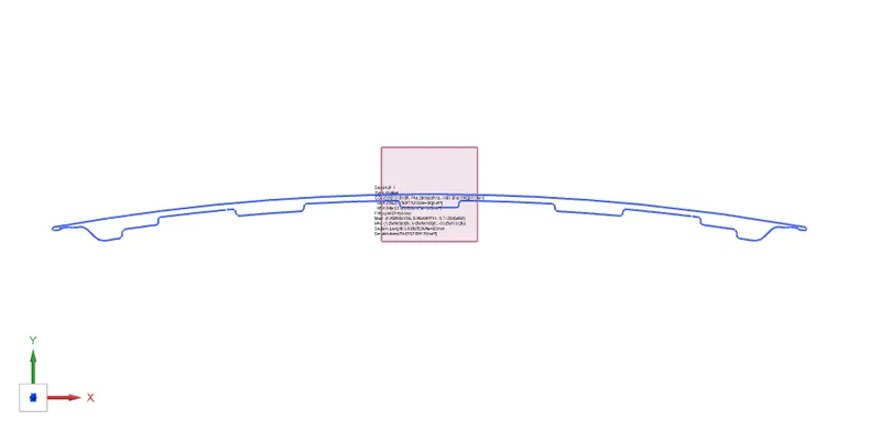
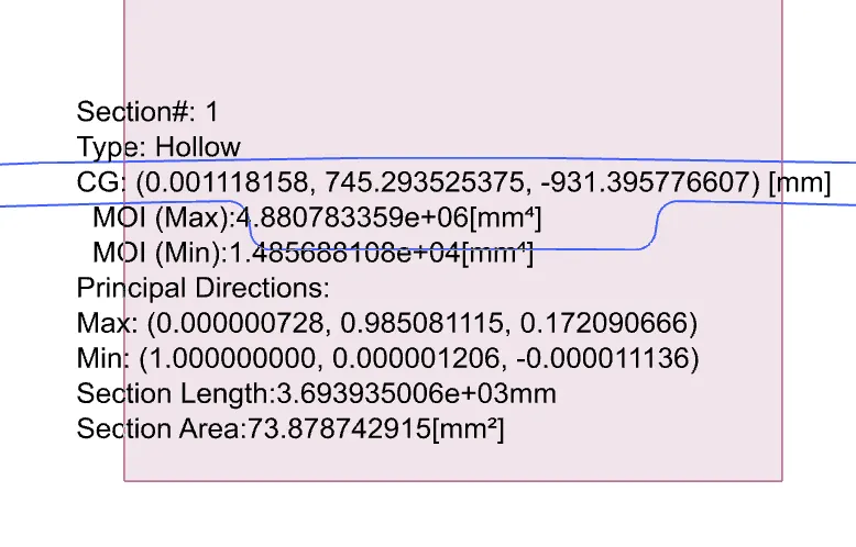
The Intersection of the design was taken and then section Inertia Analysis was done.
Calculation section:
Moment of inertia(max) = 4.880783359×10^6×mm^4
Moment of inertia(min) = 1.485688108×10^4×mm^4
Distance between the neutral axis and the extreme end of the object, y = 880.7767mm / 2 = 440.38835 mm.
Section Modulus, S = Moment of Inertia (MOI), I / Distance between the neutral axis and the extreme end of the object (y)
For Maximum (MOI),
S = (4.880783359 x 10^6 mm^4) / (440.38835 mm)
Smax = (11.082907527 x 10^3) mm^3
For Minimum (MOI),
S = (1.485688108 x 10^4 mm^4) / (440.38835mm)
Smin =33.7358630854 mm^3
Hood Design Optimization:
By increasing the depth of the inner panel by 0.5 mm
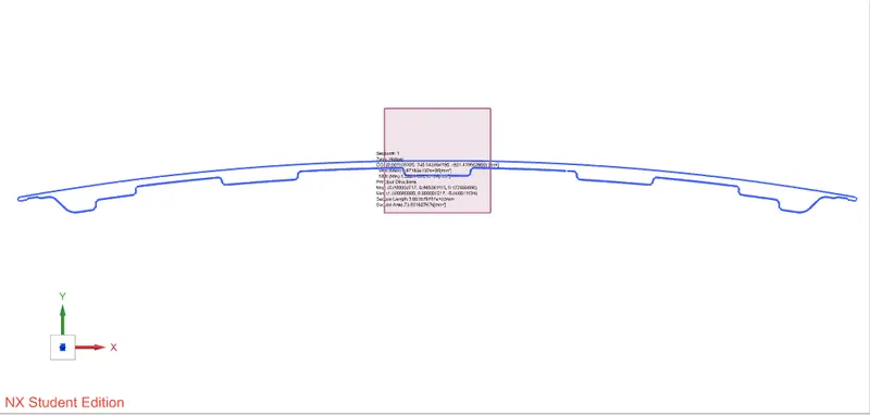
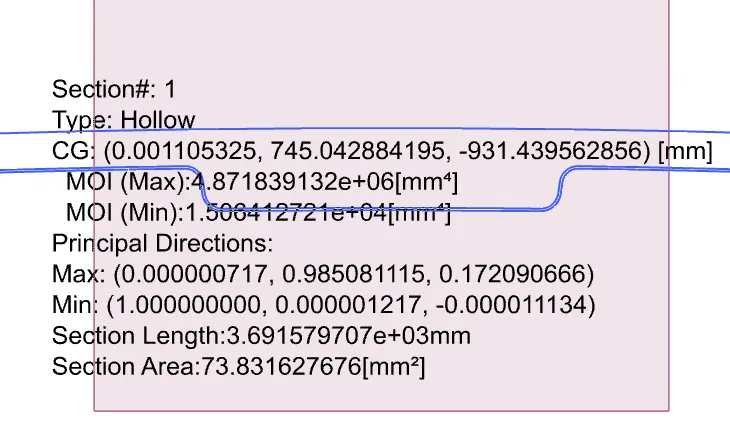
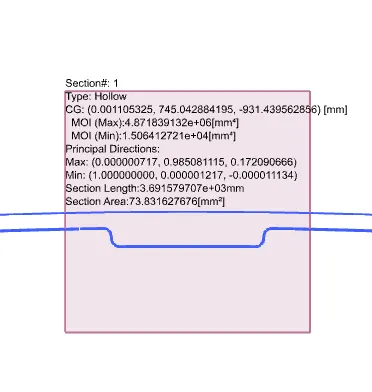
Moment of inertia(max) = 4.871839132×10^6×mm^4
Moment of inertia(min) = 1.506412721×10^4×mm^4
Distance between the neutral axis and the extreme end of the object, y = 880.7767mm / 2 = 440.38835 mm.
Section Modulus, S = Moment of Inertia (MOI), I / Distance between the neutral axis and the extreme end of the object (y)
For Maximum (MOI),
S = (4.871839132 x 10^6 mm^4) / (440.38835 mm)
Smax = (11.0625976641 x 10^3) mm^3
For Minimum (MOI),
S = (1.506412721 x 10^4 mm^4) / (440.38835mm)
Smin =34.2064616605 mm^3
CONCLUSION:
Here the Section Modulus of Hood of the car was calculated and optimized section modulus with some changes or optimization and found some better results.