Fender Design - Wheel Arch Challenge
DESIGN FENDER - WHEEL ARCH
AIM:
The wheel arch challenge is to calculate the wheel arch area using Siemens NX-CAD and to prove whether the given fender of car will pass the European standards or not.
INTRODUCTION:
WHEEL ARCH:
Wheel arch is a semicircular profile above wheels designed for enclosing tire within the fender The wheel arch is designed considering all possible motions the tire undergoes while the vehicle is in motion.
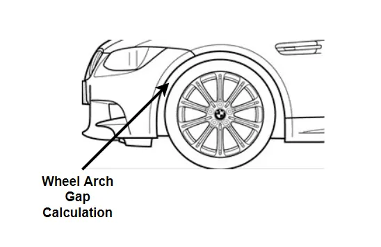
Wheel arch comes with some standard specifications. When viewed from the front or top side of the vehicle, if the wheel is protruding outside the fender, that would lead to more chipping while driving and compromises pedestrian as well as the vehicle safety. Taking these factors into consideration, the wheel has to be positioned inside the wheel.
Using the Europian Standards:
Wheel arch comes with some standard specifications. Here we were used eupian standards to calculate the dimenstions.When viewed from the front or top side of the vehicle, if the wheel is protruding outside the fender, that would lead to more chipping while driving and compromises pedestrian as well as the vehicle safety. Taking these factors into consideration, the wheel has to be positioned inside the wheel.
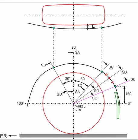
There are different regulations in this regard based on different regions. This case study has been done according to European regulations. As explained in the diagram below, the minimum clearance 'L' recommended at all the 5 points on the wheel arch shown here should be 10mm, the points being SB, SA, SC, SD, SE.
Wheel Arc Verification Using European Standards:
The important parameter which is considered in the designing of wheel arch or wheel is the clearance between wheel and fender during the vehicle bump conditions.
Requirements have been proposed by vehicle and road safety community to the minimum requirement of wheel arc distance from the wheel for safety.
The below steps to draw the sketch on the wheel face as per the European Standards-
1. Measure of CL L is done on sections SA, SB , SC, SD, SE.
2. At all sections the value of CL L should be greater that 10mm.
3. Wheel guard requirement -: The value of a shall be more that 5mm at 30 Deg forward and 50 Deg rearward from the central axis of wheel.
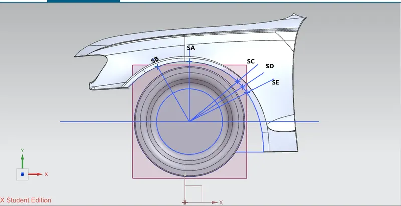
In the above fig- we have open the given file on Siemens NX CAD 12. Firstly create the point on the center of wheel and then create the center reference line. project the on the wheel arch at section SA, SB , SC, SD and SE to measure the distance / clearance 'L', 'a' and the wheel arch area.
Calculation of the clearence value"L" as following:
1.The Measuring dimention for the given wheel and fender at SB- The value of 'L' at SB= 10.0000 mm.

2. The Measuring dimention for the given wheel and fender at SA- The value of 'L' at SA= 9.9490 mm.
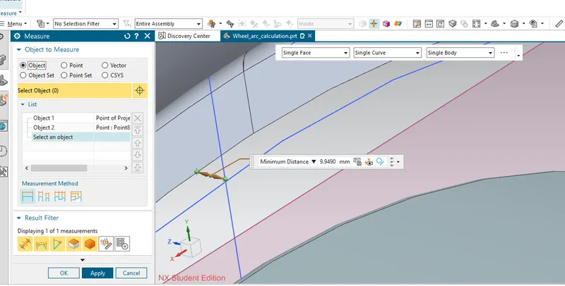
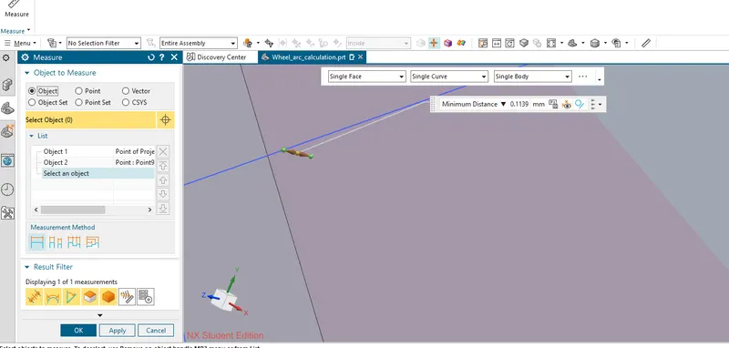
3.The Measuring dimention for the given wheel and fender at SC- The value of 'L' at SC= -0.1139 mm.
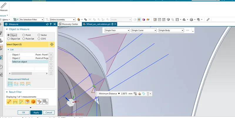
4.The Measuring dimention for the given wheel and fender at SD- The value of 'L' at SD= -2.8875 mm.
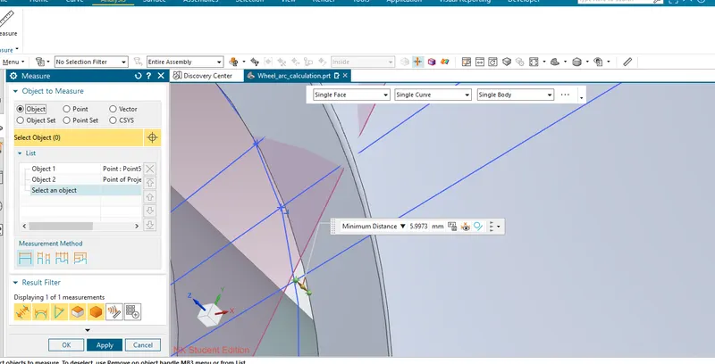
5.The Measuring dimention for the given wheel and fender at SE- The value of 'L' at SE= -5.9973 mm.
Tabulation:
| Section | Calculated clearance (in mm) | Minimum clearance to pass (in mm) | Pass/Fail |
| SB | +10 mm | +10 mm | Pass |
| SA | +9.9490 mm | +10 mm | Fail |
| SC | -0.1139 mm | +10 mm | Fail |
| SD | -2.8875 mm | +10 mm | Fail |
| SE | -5.9973 mm | +10 mm | Fail |
From the comparing above three section (like SC, SD and SE) the fender doesn't pass the European standards for the wheel arch.the one section which is(SA+9.9490<10MM) very close to the europian standards.The only one section is passed the europian standard which is (SB 10MM).Negative sign indicates that the wheel arc is behind the wheel
CONCLUSION:
Therefore the wheel arch does not meets the requirements as per the European standards. So the design team needs to work on the section of SC, SD, and SE. For safety purpose the wheel arc should be outside the wheel and the value greater than 10mm and the SD, SE fender section should come outside the wheel.