Roof Design
AUTOMOTIVE SHEETMETAL ROOF DESIGN USING NX CAD
AIM:
In this project, I am going to the Design of Roof and Develop the Essential Flanges and Reinforcements, and check for Draft analysis and also section modulus report on the 0-Y section.
INTRODUCTION:
An automobile roof is the portion of an automobile that sits above the passenger compartment, protecting the vehicle occupants from sun, wind, rain, and other external elements. Though it just looks like a styling surface that protects from sun, wind and other elements, various environmental conditions are taken into account for designing of the same. Roof should be provided with proper reinforcements for strengthening. Vehicle roof can be subjected to high heat conditions or load during snowy conditions. To make the roof withstand these conditions, various calculations are done. This ensures the safety of the passengers in the vehicle.
Abstract:
Safety point of view vehicle roof plays very crucial role specially roll over kind of accidents, in which vehicle tips over onto its side of roof. And vehicle rollover crashes are the causes of many fatalities and several head, neck and spine trauma around the world. Therefore passenger safety is also very important parameter in front of OEM’s. It is not onl a marketing strategy but also it is a obligation stipulated by international standards that are now place in several countries, as well as a governmental requirement. For this reason strength is very important criteria for designing vehicle roof.
DESIGN CONSIDERATION OF ROOF:
- Visibility criteria
- Head room clearance
- Bow roof position
- Heat distortion and Snow load criteria
- Draft analysis
REINFORCEMENTS :
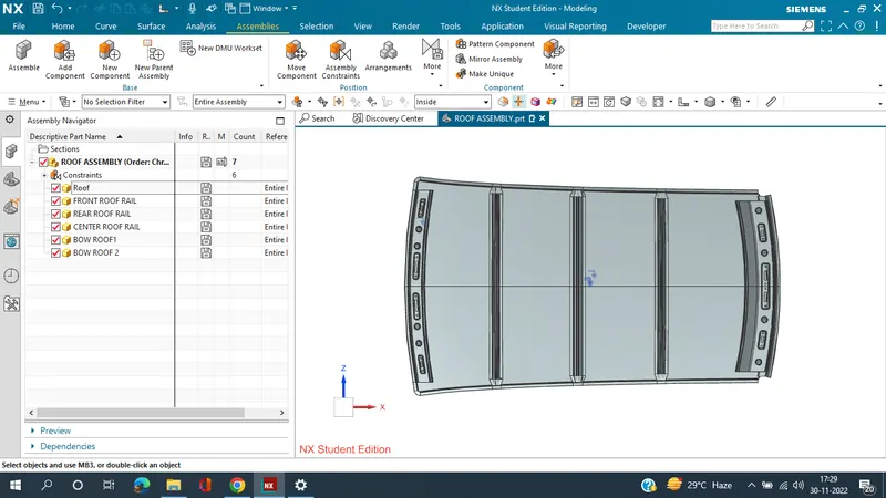
If the roof is flat it is very weak and cannot able to with stand the forces like snow , so in order to increase the strength of the roof these reinforcements like front roof rail, central roof rail, rear roof rail and the bow roofs are introduced and joined to the flat surface of the roof with the different joining process
Different types of reinforcements that the car has are :
- Front roof rail
- Bow roofs
- Central roof rail and
- Rear roof rail
FRONT ROOF RAIL :
Front roof rail is the one which joins the wind shield glass , body side outer and the inner panel also. Here the front roof rail is designed based up on the master saection given
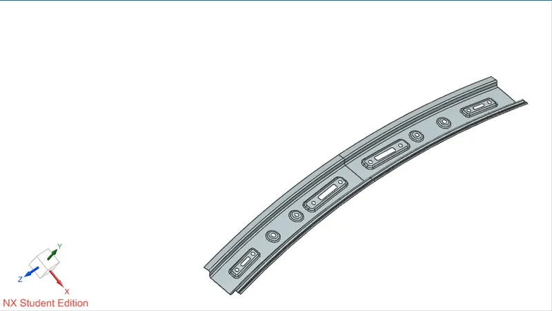
REAR ROOF RAIL :
Rear roof rail is the one which joins the back door and the body side outer
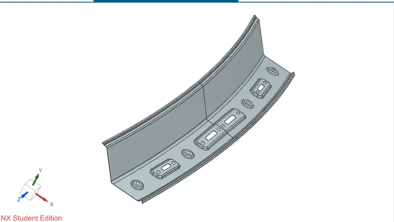
CENTRAL ROOF RAIL :
central roof rail helps in providing effectively support to the flat area of the roof as it is more susceptible to failure under the action of load . generally central roof rail is placed at the center of the roof which is connected to the B-pillar support structure . This central roof rail helps in adding the strength to the roof during the rool- over test.
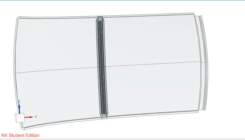
BOW ROOFS :
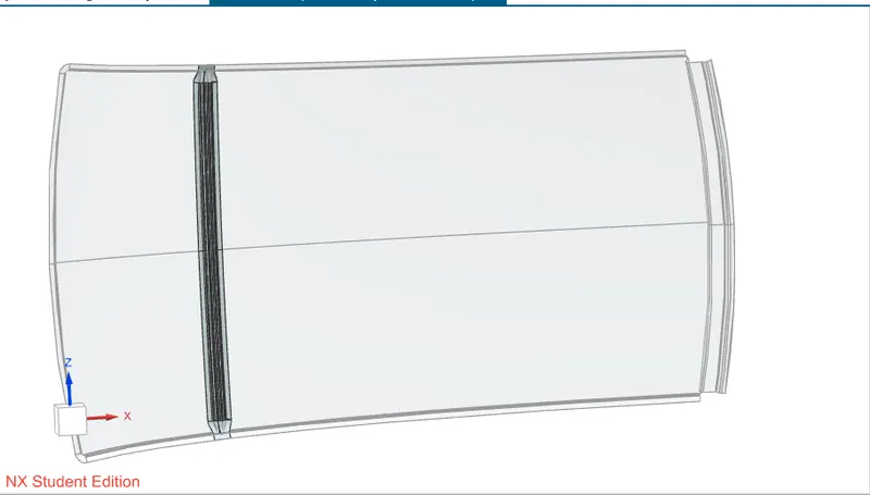
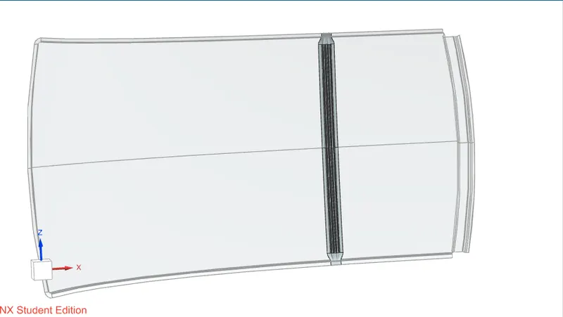
The bow roofs are give to improve the torsional stiffness and load bearing capacity of the roof structure . The number of bow roof present is depends on the overall size of the roof . Presently in this project two bow roofs are added.
TESTING:
Roof strength evaluations are conducted on a quasi-static test system manufactured by MGA Research Corporation.
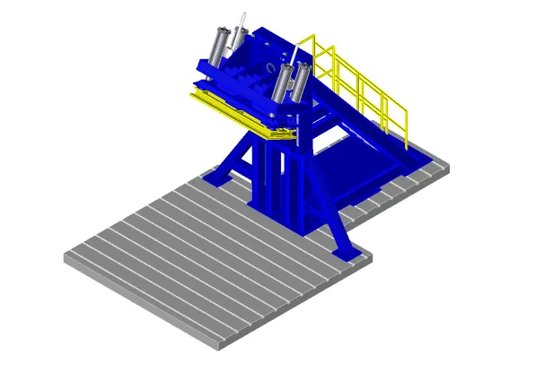
The system consists of an upright assembly and an attached loading head that can be fixed at varying heights from the ground and at pitch angles ranging from −5 to +5 degrees to accommodate testing on the driver or passenger side.The roll angle is permanently fixed at 25 degrees.Four hydraulic actuators control the movement of the platen along two linear guides.The entire system is mounted on a T-slot bed plate anchored to the floor of the test facility.
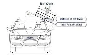
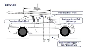
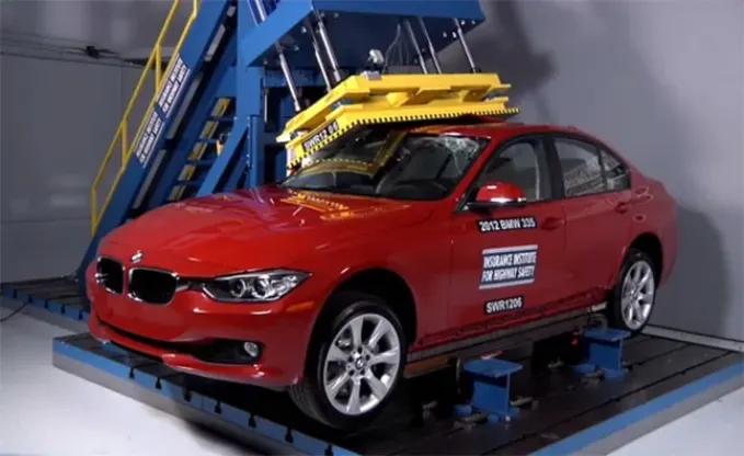
To measure the roof strength of a vehicle, IIHS has a metal plate pushed against one corner of a vehicle’s roof at a constant speed. The maximum force sustained by the roof before five inches of crush is compared to the vehicle’s weight. From there, IIHS calculates a strength-to-weight ratio.
Two HR A-36 — W10x88 I-beams are mounted on the bed plate perpendicular to the longitudinal axis of the platen. The vehicle, with attached rocker panel support system, is placed on these beams. The vehicle is adjusted so that:
RESULTS :
If the displacements goes above the requirements level then we have to increase the bow roof thickness or add more mastics points to increase the strength . the stronger the roof the better it can protect the occupants in the roll over crashes.
HEAT DISTORTION STUDY ON THE ROOF :
The heat distortion study plays a major role in sheet metal usage . heat distortion temperature is a temperature limit above which the Material cannot be used for the structural applications . This study is used to predict the heat distortion temperature at where the material starts to soften when exposed to a fixed load at elevated temperature . In order to avoid bending or damages on the roof, based on the heat distortion temperature , this study will predict the bow roof position which helps to strengthen the roof.
Bow – roof prediction Formula
W = [1.73 x 10^(-3) x L] + [1.85 x 10^(-8) x (R^2)/t] + [ 1.10x10^(-3) x l] - 2.68
Where
L = Roof Length in X-Direction[mm](Roof dimension in 0-Y)
R = Roof curvature
R = 2(Rx*Ry)/(Rx+Ry)
Rx = X curvature
Ry = Y curvature
t = Roof plate thickness [mm]
l = Bow Roof Span [mm]
Judgement Condition : OK< 2.7> 3.1
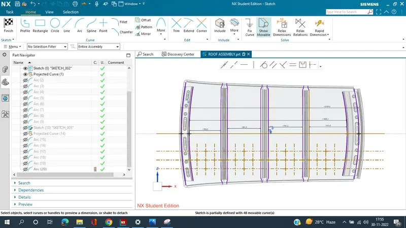
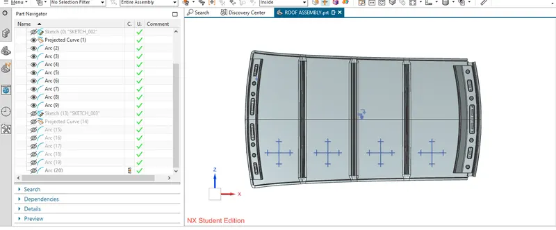
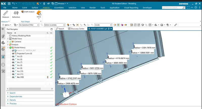
APPLY THE VALUES IN THE FORMULA :
In order to find the heat distortion apply all the necessary values from the roof to the give formula
CALCULATIONS :
| HEAT DISTORTION CRITERIA | ||||||||
| ROOF RAILS | RX(MM) | RY(MM) | R(MM) | t(MM) | I(MM) | L | W | RESULTS |
| FRONT ROOF-BOW ROOF1 | 5740.3107 | 2498.4676 | 3481.5793 | 0.75 | 363.5 | 2025.6 | 1.5231324 | PASS |
| BOW ROOF1 - CENTER ROOF | 5051.07 | 5879.123 | 5433.7227 | 0.75 | 381.5 | 2025.6 | 1.972238 | PASS |
| CENTER ROOF -BOW ROOF 2 | 4116.6674 | 9885.4964 | 5812.716 | 0.75 | 391.3 | 2025.6 | 2.088148 | PASS |
| BOW ROOF2 - REAR ROOF | 3391.768 | 13866.931 | 5450.4013 | 0.75 | 431.5 | 2025.6 | 2.031708 | PASS |
From the above table it can be concluded that all values of w<2.7 and also not w>3.1 so thus infers that current positioning of bow row are good in state as per design and found ok
SNOW LOAD CRITERIA :
This test is done to know how is the roof behaving when there is a snow over . normally due to the snow weight the dent will happen. But the roof should be designed in such a way that when the snow is removal the roof should go it its original position . This is the basic requirements for snow load criteria.
SNOW LOAD CRITERIA:
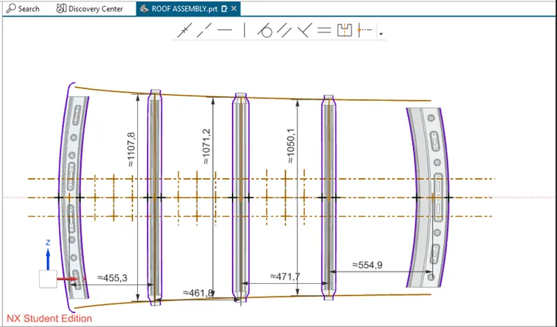
Qr = [IY x t2] / [α x s x [(RX + RY)/2]2 x 10-8]
Where,
α = My x LX2 x10-12, My = Y(Ly–Y)
Judgement condition = Qr > 3.1
250 < s < 380
t = Roof plate thickness[mm]
LY = Distance between the front and rear roof rails on the vehicle along with 0Y[MM],
Length of roof panel with the center point between roof rails front/ rear as the front and rear reference point.
LX= Distance between the left and right end of the roof on the roof bow[mm],
With of the roof panel exposed on the surface.
Y = Distance between Front roof rails to roof bow [mm],
s = Distance for which roof bow bears divided load [mm],
s = L1/2 + L2/2
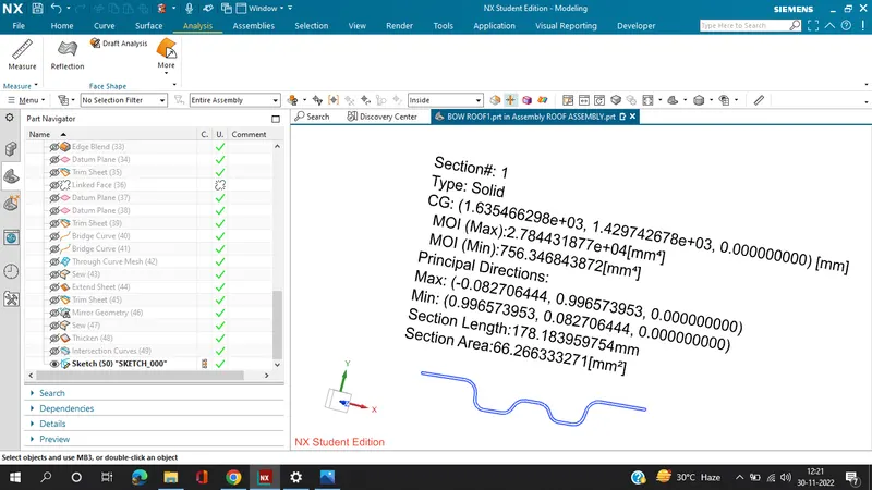
Iy = Geometrical moment of inertia of roof bow (Y cross – section) [mm4],
RX = Lateral direction curvature radius of roof panel Y cross section on roof bow [mm4],
Roof panel curvature radius of the length LX in front view.
RY = Longitudinal direction curvature radius of the roof panel X cross section on roof bow[mm4],
Roof panel X curvature radius of length s in side view.
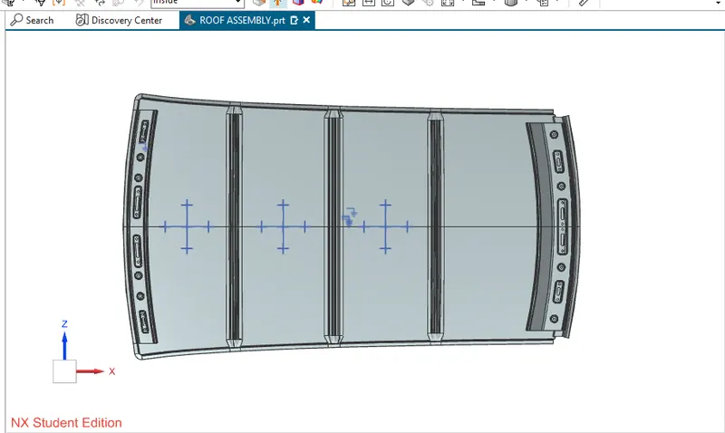
Section analysis:
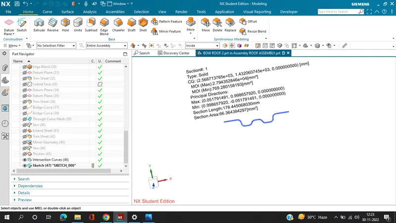
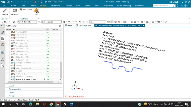
Section moment of inertia is used to predict the amount of deformation and deflection of a part. A higher moment of inertia is preferable as it reduces the amount of deflection for a given force. The thickness of the part and addition of flanges and embosses increase the section inertia of the part. Here the master sections of the roof and roof rails and their section analysis are given.
SNOW LOAD CALCULATIONS:
|
SNOW LOAD CRITERIA |
|||||||||||
|
ROOF RAILS |
IY |
RX |
RY |
ALPHA |
t |
LX |
LY |
Y |
S |
QR |
RESULTS |
|
FRONT ROOF-BOW ROOF1 |
756.3468439 |
4593.8281 |
2512.4053 |
0.83045 |
0.75 |
1107 |
1943.7 |
455.3 |
458.55 |
8.84962 |
PASS |
|
BOW ROOF1 - CENTER ROOF |
1782.023935 |
3754.9391 |
5772.8336 |
1.08051 |
0.75 |
1071.2 |
1943.7 |
918.5 |
466 |
8.771997 |
PASS |
|
CENTER ROOF -BOW ROOF 2 |
769.2801582 |
4202.4944 |
10240.7072 |
0.849799 |
0.75 |
1050.1 |
1943.7 |
1388.8 |
513.3 |
1.902186472 |
NA |
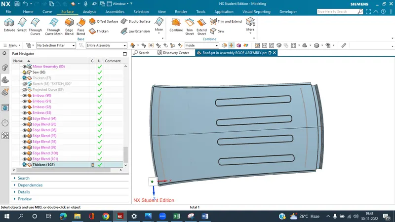
This shows that at the third section, design does not fulfil snow load criteria.Hence, to increase the strength of the roof, embosses are provided on the roof surface.
DRAFT ANALYSIS :
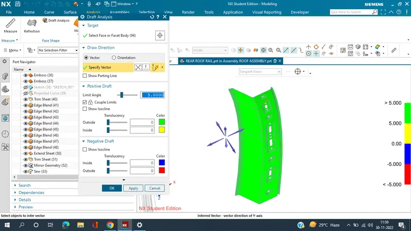
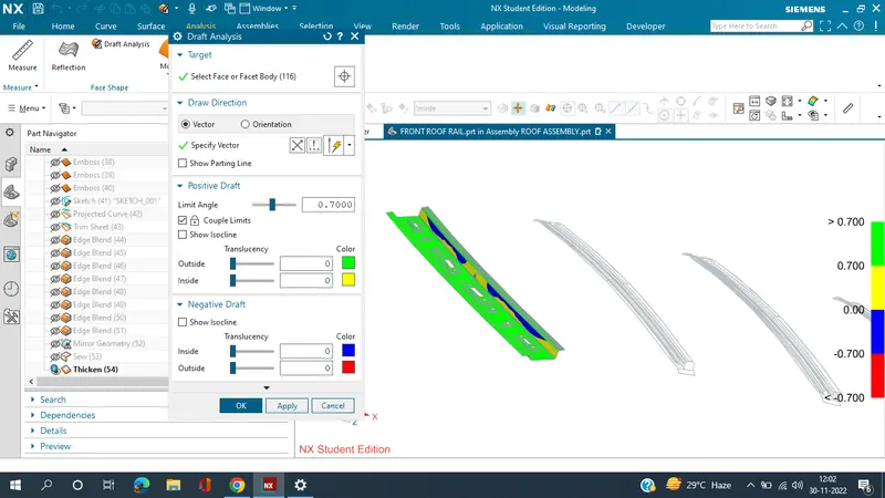
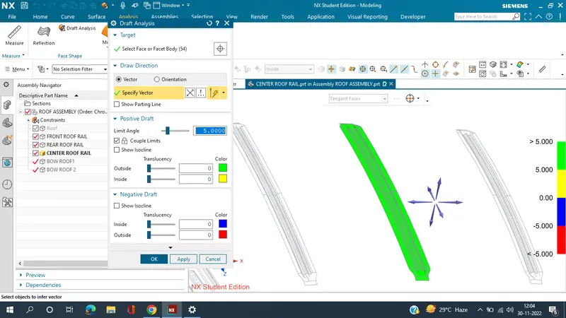
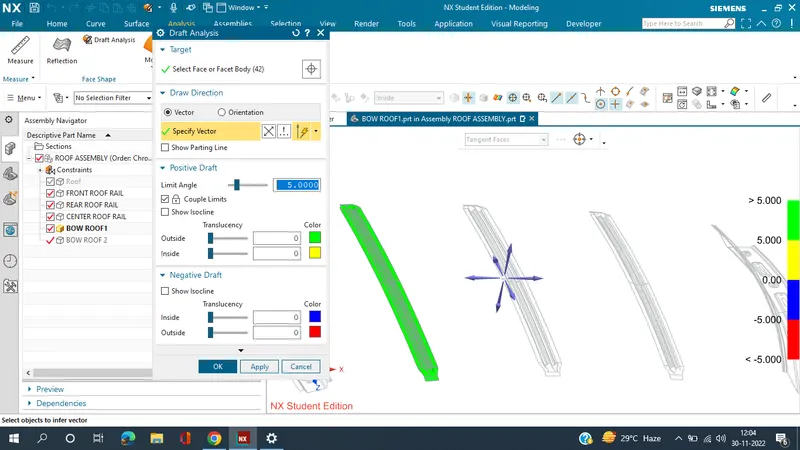
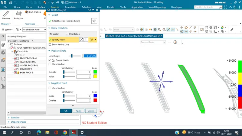
The Draft Analysis command enables you to detect if the part you drafted will be easily removed. This type of analysis is performed based on color ranges identifying zones on the analyzed element where the deviation from the draft direction at any point, corresponds to specified values.
Minimum draft angle of 70 is considered for analysis . green colour infer on the parts that all face along the tooling direction has positive draft angle greater than 70 and passed in analysis 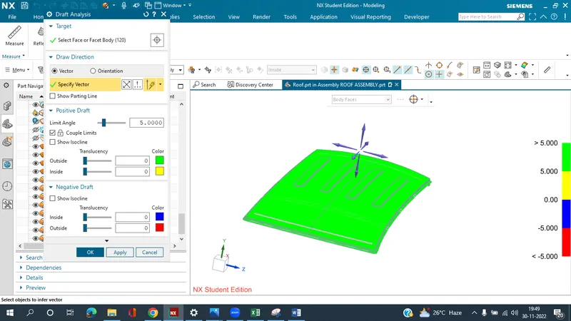
CONCLUSION :
Hence the roof , front roof rail, bow roof rails , central roof rail and the rear roof rail is designed by following the master sections and the moment of inertia and draft analysis are carried out to check feasibility manufacturing.