Week 8 - Challenge 2 - Switch Bezel Design
AIM:
To Create the Switch Bezel Plastic component through the given Class-A surface. To begin with, the tooling axis for the given Class-A Surface should be created meeting the requirements of the draft angle and at the end perform the Draft analysis on the model.
Surface creation:
There is three types of surface creation will perform this module
- CLASS-A Surface
- CLASS-B Surface
- CLASS-C Surface
CLASS-A Surface:
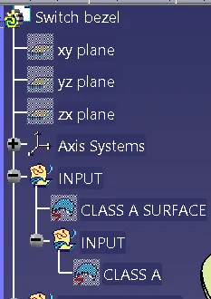
Class-A surface means visible surface. It gives the aesthetic of the component which is created by the styling team and gives to the part design engineer to create the part with all engineering aspects.
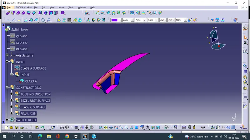
CLASS-B Surface
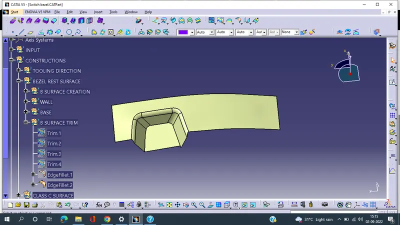
Class-B surface means thickness of a part In other words, Class-B surface is a surface below a certain thickness from the class-A surface. This is the surface that contains engineering aspects of a model.
CLASS-C Surface
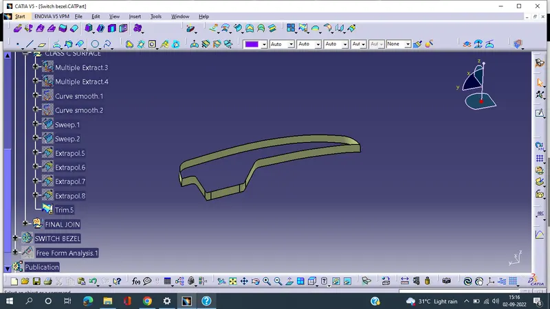
Surface that joins class-A and class-B surfaces is class-C surface. Class C is often specified for interior surfaces not readily visible, surfaces that will be covered by another part when assembled
Tooling Direction & Create Bisecting Line:
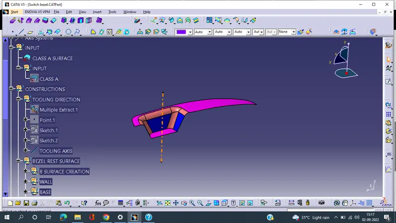
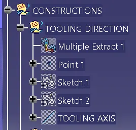
The tooling direction would be at the z-axis because at that direction it is very easy to manufacture and all the and all faces and the entire surface are to be covered in that direction without adding any other equipment
Bisecting, the articular surface is a tool or not we intersect the surface with the respective plane and get a sketch which consist of two lines, and with the help of bisecting line option, we bisect the line which creates a line at the midpoint of the two lines. Likewise, we create a tooling clearing axis for x and y which will be used to create the main tooling axis using the bisecting line option in the line command.
Draft Analysis:
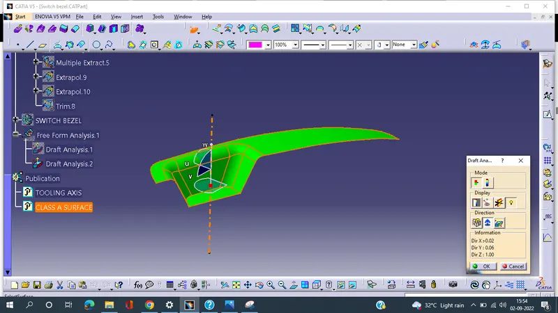
The Draft Analysis command enables you to detect if the part you drafted will be easily removed. This type of analysis is performed based on colour ranges identifying zones on the analysed element where the deviation from the draft direction at any point, corresponds to specified values.
Draft analysis is done after determining the tooling axis, draft analysis is used to check whether the minimum draft angel 3 degree is maintained or not.
draft analysis of class A surface:
Draft analysis of final part:
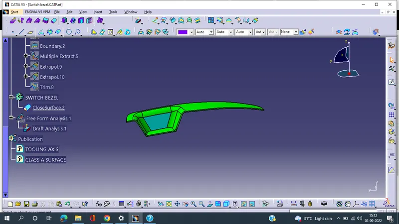
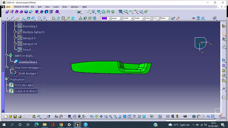
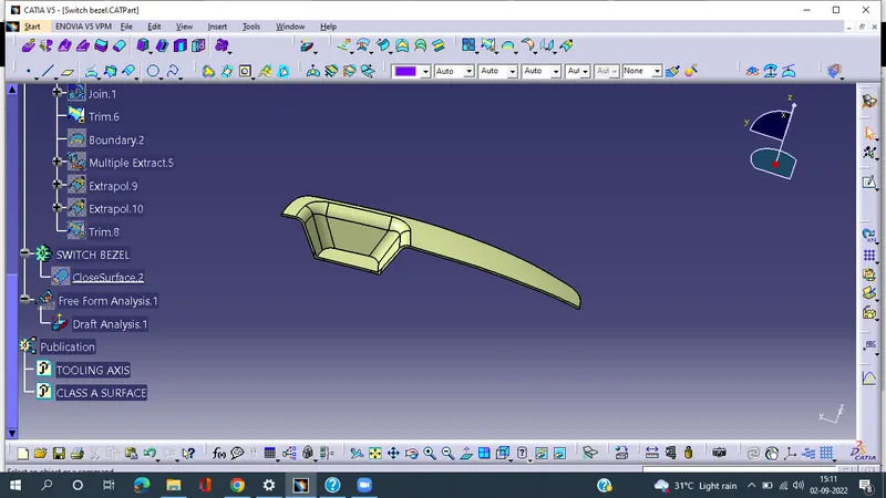
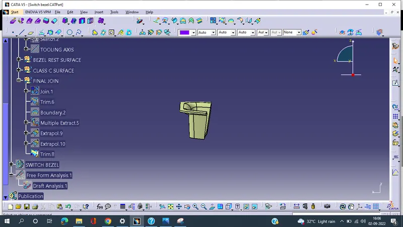
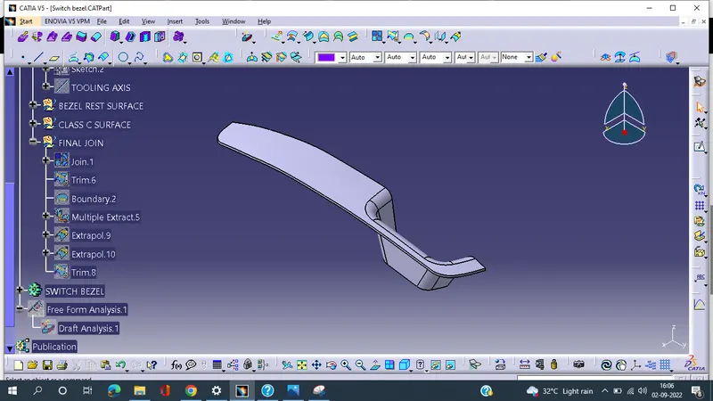
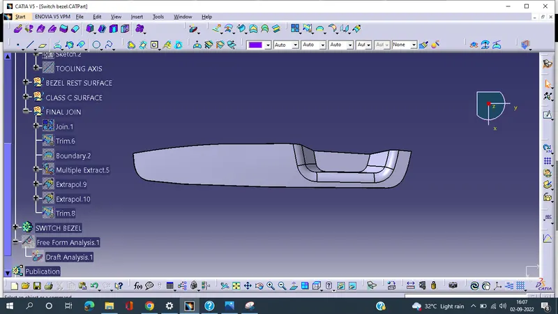
final part views:
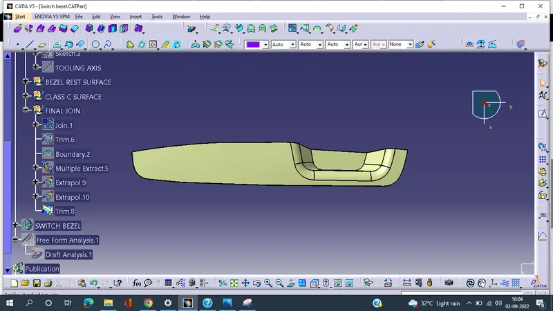
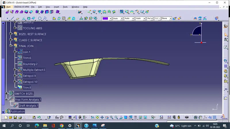
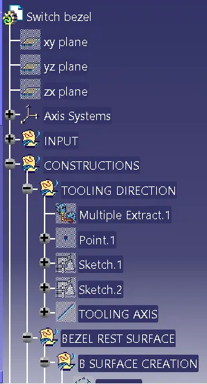
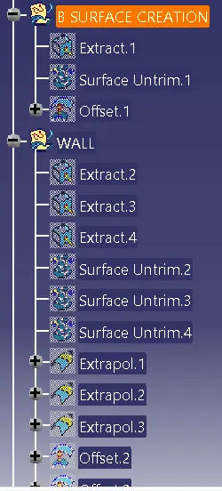
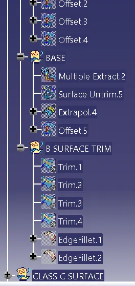
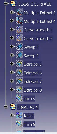
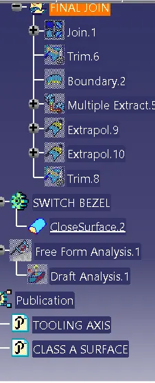
The expanded Tree Structure for the geometrical set and the Part Body:
Conclusion:
I have successfully created the class-B and Class-C surfaces of Switch Bezel using the given Class-A surface along with the tooling axis in the CATIA surface workbench. And also created the final part body using the close surface command in the part design workbench and performed draft analysis for the same.