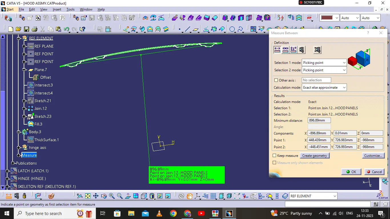
Section Modulus calculation and optimization
Section modulus :
It is a geometric property for a given cross-section used in the design of beams or flexural members. Other geometric properties used in design include area for tension and shear, radius of gyration for compression, and second moment of area and polar second moment of area for stiffness. Any relationship between these properties is highly dependent on the shape in question. Equations for the section moduli of common shapes are given below. There are two types of section moduli, the elastic section modulus and the plastic section modulus. The section moduli of different profiles can also be found as numerical values for common profiles in tables listing properties of such.
Notation
North American and British/Australian convention reverse the usage of S & Z. Elastic modulus is S in North America, but Z in Britain/Australia,and vice versa for the plastic modulus.Eurocode 3 (EN 1993 - Steel Design) resolves this by using W for both, but distinguishes between them by the use of subscripts - Wel and Wpl.
Elastic section modulus
For general design, the elastic section modulus is used, applicable up to the yield point for most metals and other common materials.
The elastic section modulus is defined as S = I / y, where I is the second moment of area (or area moment of inertia, not to be confused with moment of inertia) and y is the distance from the neutral axis to any given fibre. It is often reported using y = c, where c is the distance from the neutral axis to the most extreme fibre, as seen in the table below. It is also often used to determine the yield moment (My) such that My = S ⋅ σy, where σy is the yield strength of the material.
| Cross-sectional shape | Figure | Equation | Comment |
|---|---|---|---|
| Rectangle | �=�ℎ26 |
Solid arrow represents neutral axis | |
| doubly symmetric I-section (major axis) | ��=��26−�ℎ36�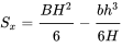
��=��� with �=�2 |
NA indicates neutral axis | |
| doubly symmetric I-section (minor axis) | ��=�2(�−ℎ)6+(�−�)3ℎ6�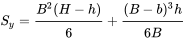 |
NA indicates neutral axis | |
| Circle | �=��332 |
Solid arrow represents neutral axis | |
| Circular hollow section | �=�(�24−�14)4�2=�(�24−�14)32�2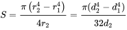 |
Solid arrow represents neutral axis | |
| Rectangular hollow section | �=��26−�ℎ36�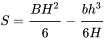 |
NA indicates neutral axis | |
| Diamond | �=��224 |
NA indicates neutral axis | |
| C-channel | �=��26−�ℎ36� |
NA indicates neutral axis |
 ,

Plastic section modulus
The plastic section modulus is used for materials where elastic yielding is acceptable and plastic behavior is assumed to be an acceptable limit. Designs generally strive to ultimately remain below the plastic limit to avoid permanent deformations, often comparing the plastic capacity against amplified forces or stresses.
The plastic section modulus depends on the location of the plastic neutral axis (PNA).The PNA is defined as the axis that splits the cross section such that the compression force from the area in compression equals the tension force from the area in tension. So, for sections with constant, and equal compressive and tensile yielding stress, the area above and below the PNA will be equal, but for composite sections, this is not necessarily the case.
The plastic section modulus is the sum of the areas of the cross section on each side of the PNA (which may or may not be equal) multiplied by the distance from the local centroids of the two areas to the PNA:
��=����+����
The Plastic Section Modulus is not the 'First moment of area'. Both relate to the calculation of the centroid, but Plastic Section Modulus is the Sum of all areas on both sides of PNA (Plastic Neutral Axis) and multiplied with the distances from the centroid of the corresponding areas to the centroid of the cross section, while the First moment of area is calculated based on either side of the "considering point" of the cross section and it is different along the cross section and depends on the point of consideration.
Uniformly distributed load
Uniformly distributed load is also expressed as U.D.L and with value as w N/m. During determination of the total load, total uniformly distributed load will be converted in to point load by multiplying the rate of loading i.e. w (N/m) with the span of load distribution i.e. L and will be acting over the midpoint of the length of the uniformly load distribution.
Uniformly varying load
We can see from figure that load is zero at one end and increases uniformly to the other end. During determination of the total load, we will determine the area of the triangle and the result i.e. area of the triangle will be total load and this total load will be assumed to act at the C.G of the triangle.
FIRST INTERSECTION :
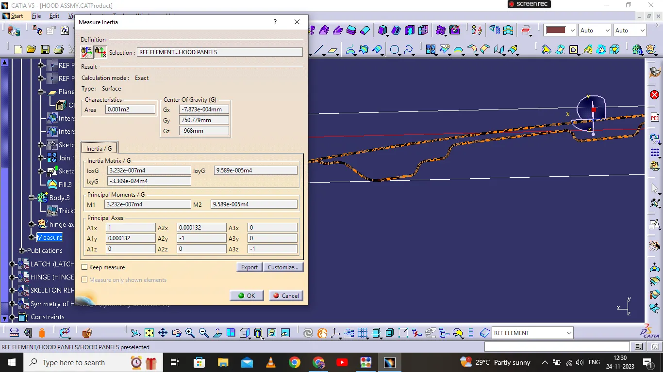
Z=I/Y
I=3.232e^-007m^4
Y=448.445mm
Z=3.232e^-007m4/448.445mm
Z=6.661159103*10^-3m^3
SECOND INTERSECTION :
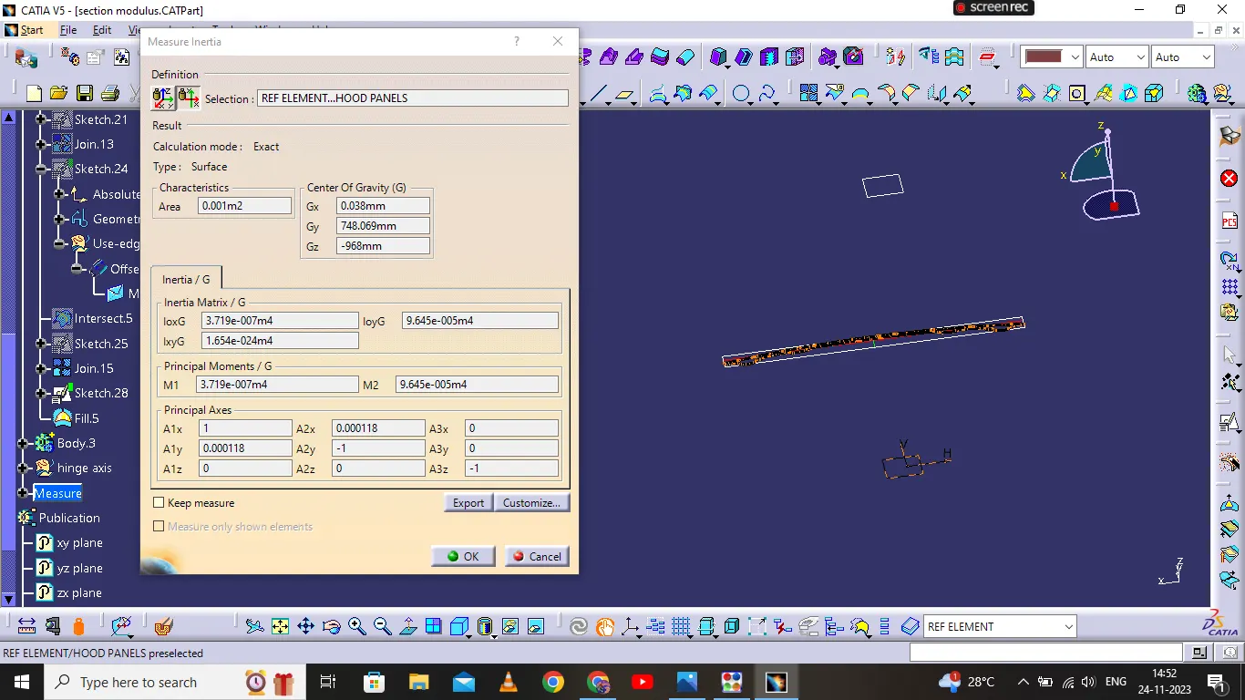
Z=I/Y
I=3.719e^-007m4
Y=448.445mm
Z=3.719e^-007m4/448.445mm
Z= 7.562301759*10^-3m^3