Roof Design
AIM:
To create an ASSEMBLY by developing the essential flanges for the outer roof and creating the front roof rail, rear roof rail, center roof rail with reinforcements, and bow roof with the Given Roof styling.
OBJECTIVE:
- To design a roof and its internal components.
- To Provide appropriate dimensions and check for Draft analysis.
- To determine the position of the Bow-roofs using the curvature study.
- To determine the heat distortion and snow load for the roof.
- To give a minimum of 7 degrees angle in roof flanges.
- To develop the reinforcements as separate parts.
INTRODUCTION:
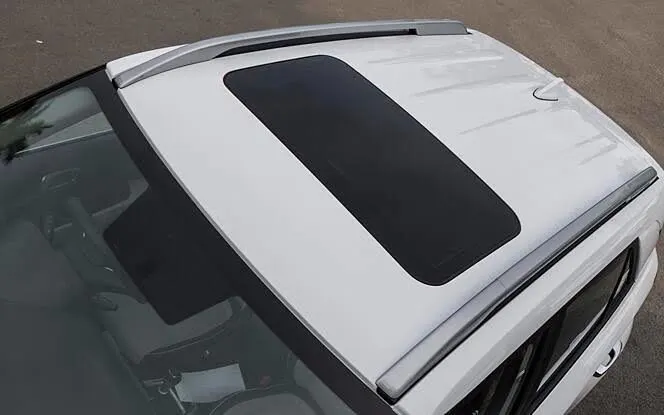
Automobile Roof is present on the top portion of the car, which plays an important role by connecting BIW parts like ABC pillars and providing protection from various weather conditions.
DESIGN:
ROOF:
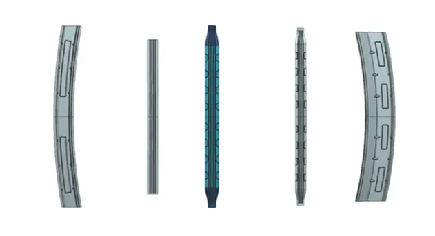
The roof has a flange on four sides but we focused on the front and rear sides of the roof because to place and spot-weld the front roof rail and rear roof rails. Cut out for sunroof is also given.
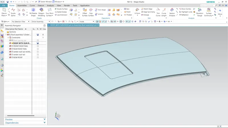
The front side of the roof is made of a flange with 7 degrees draft angle, and given enough space for windshield glass.
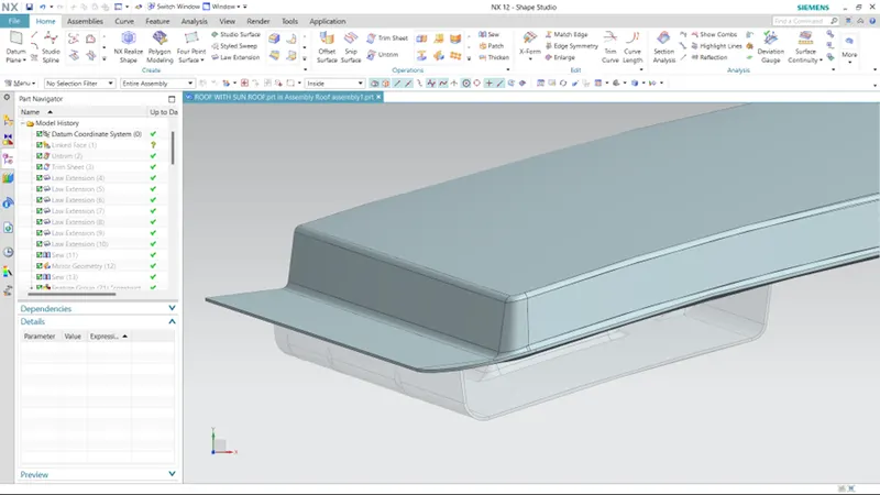
*The corners are curved using a bridge curve and studio surface and a 2.2mm edge blend radius is given.
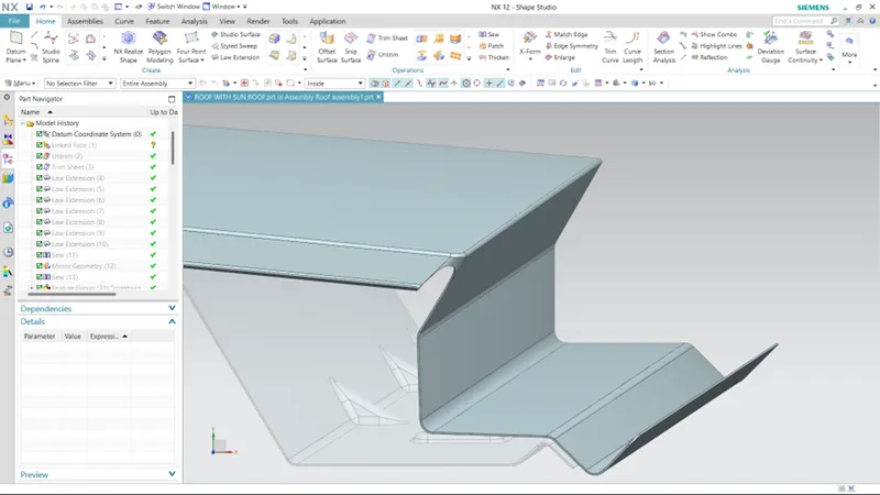
The rear side of the roof is made of a flange with 25-30 degrees of angle to provide enough space for trajectory radius to open and closing of the back door.
FRONT ROOF RAIL:
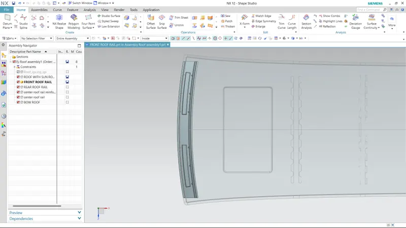
The front roof rail is to reinforce the roof, made with standard dimensions and a master section, and provided a mastic area for NVH purposes. It is spot welded to the roof.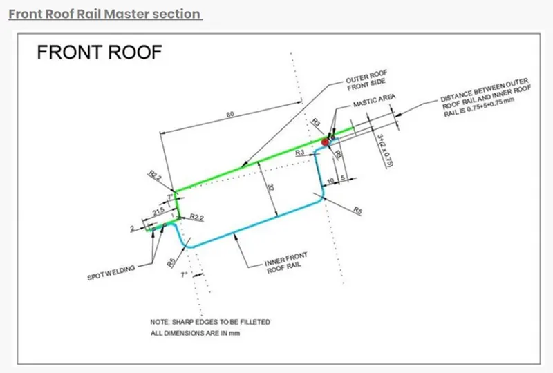
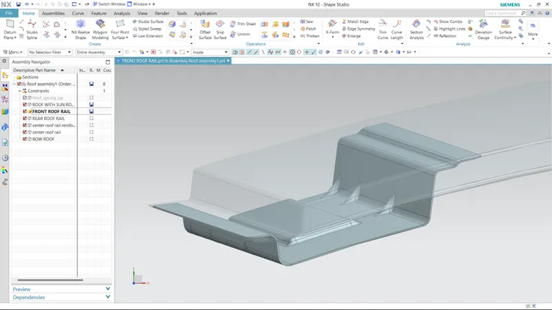 *The embosses and dart is given to increase the strength.
REAR ROOF RAIL:
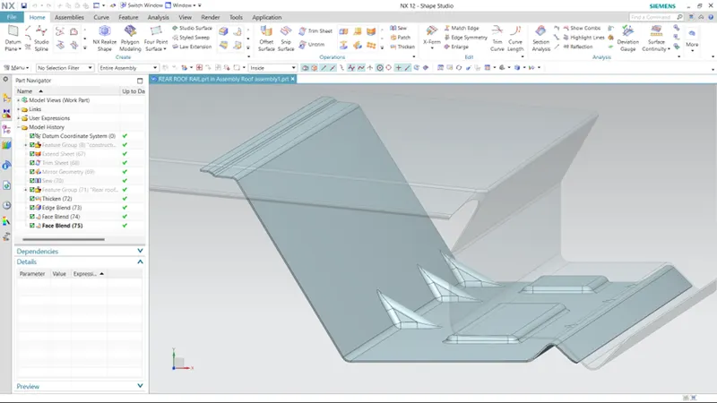
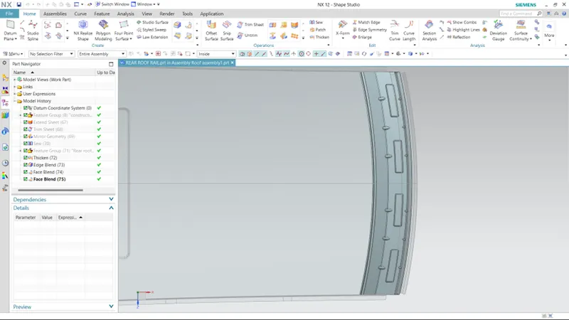
It is the same as the front roof rail that has been designed with a master section and mastic area.

CENTER ROOF RAIL WITH REINFORCEMENT:
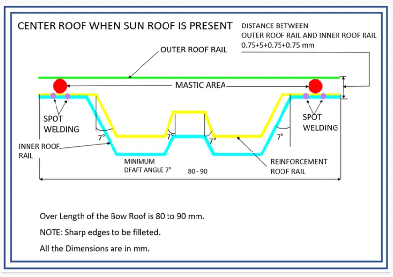
The Center roof rail has a reinforcement because of the presence of a sunroof. The reinforcement has mastic points for that embosses given in the reinforcements so that mastic glue oozes out. To spot weld each other perfectly cut out is given to the center roof rail where the embosses are presented.
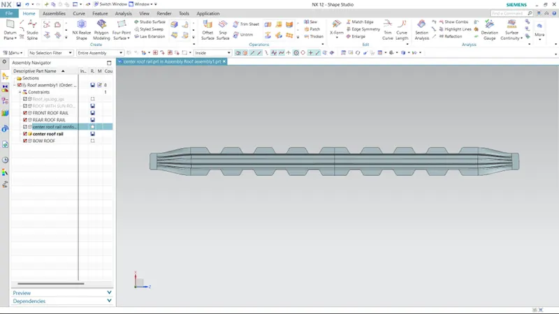
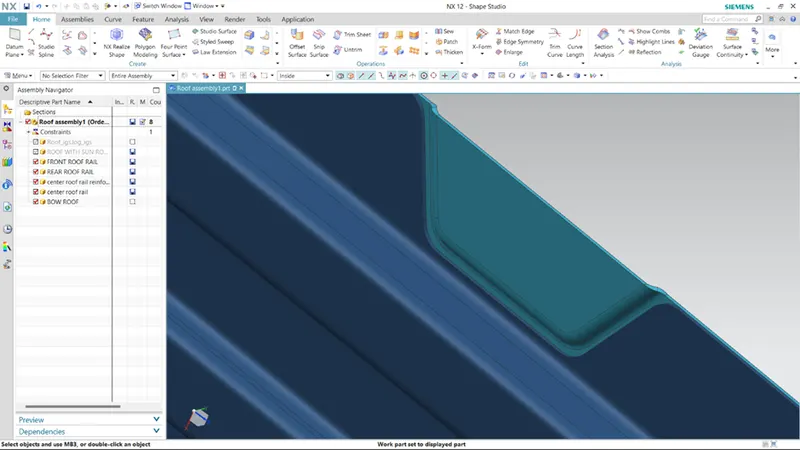
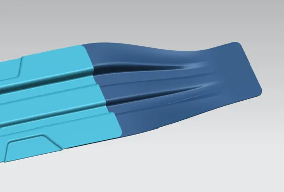
This is the part that is spot welded with the roof side flange, it is created using a studio curve
Steps I followed
trimed and offseted the flange from roof side flange
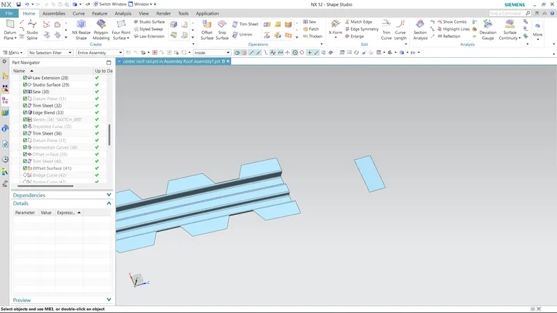
draw two curves using bridge curve with respective edges.
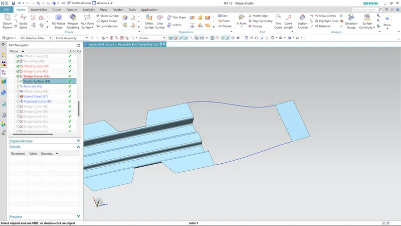
create a surface using studio surface option and bridge as a guide curve, but aesthetics of a surface is bad. in order to solve the problem, is to create more guide curve. so I extended the surface, by using projected curves recquired curves is obtained in trim sheet.
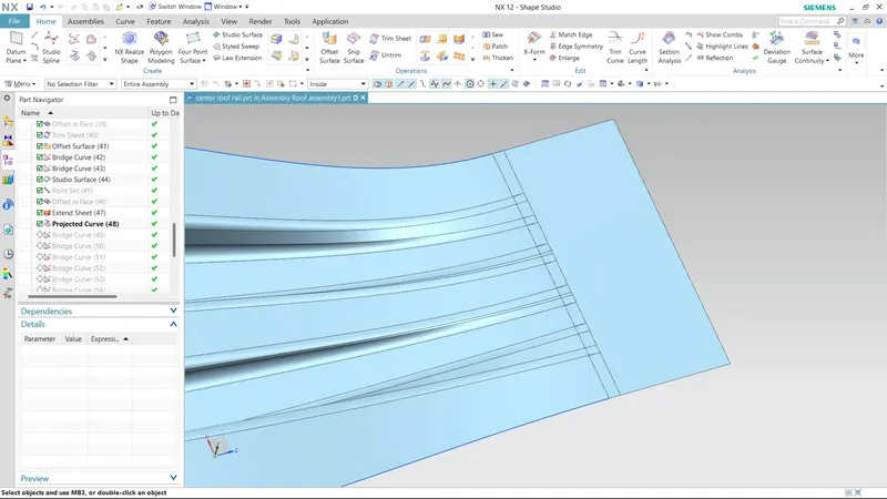
with the help of projected curves, more bridge curve is created
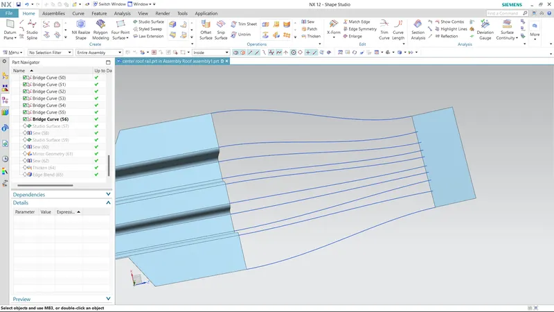
by using guid curve studio surface is designed, it is better than before but still it has a aesthetics issue, so I split it into two or more studio surfaces.
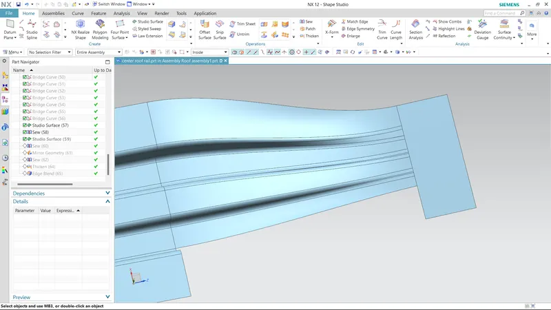
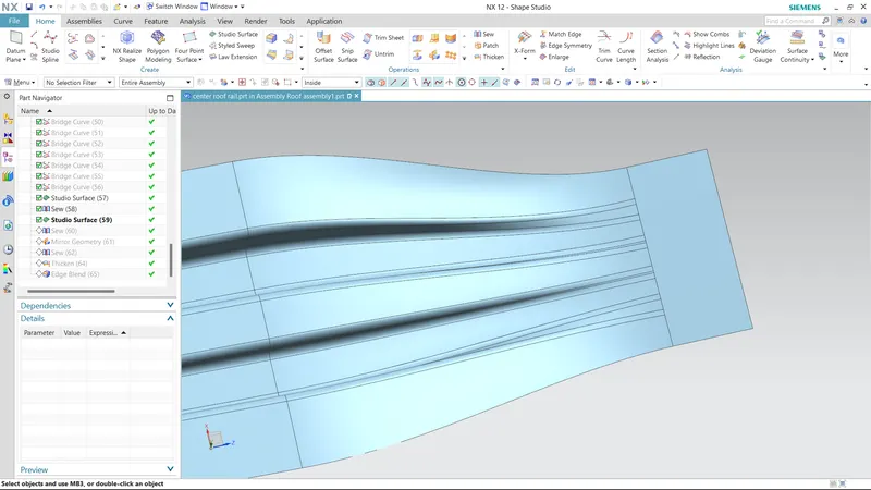
BOW ROOF RAILS:
The bow roof is almost the same as the center roof rail, the difference is it has mastic points that stick together with the roof, but, In the center roof rail may or may not have either mastic points or reinforcement which means it differs according to the roof whether it is connected together or not.
so in this design, it has both reinforcement because of the sunroof and mastic points, so I used one bow roof 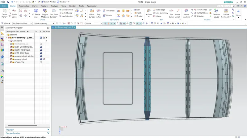
if it has no sunroof then there will be two bow roof
ANALYSIS:
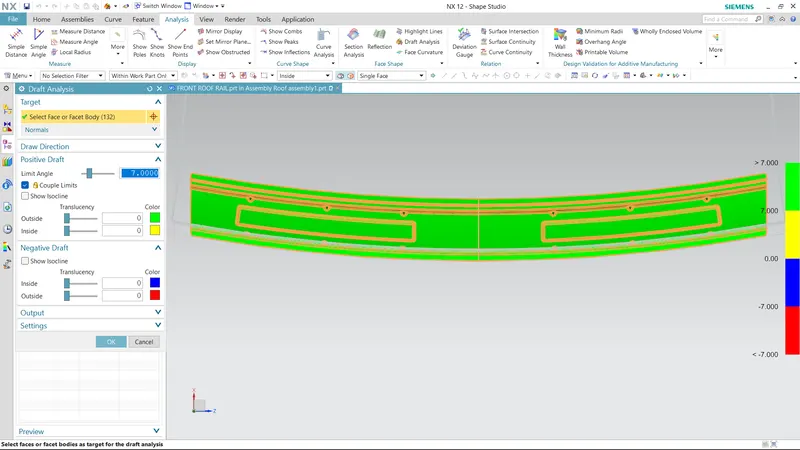
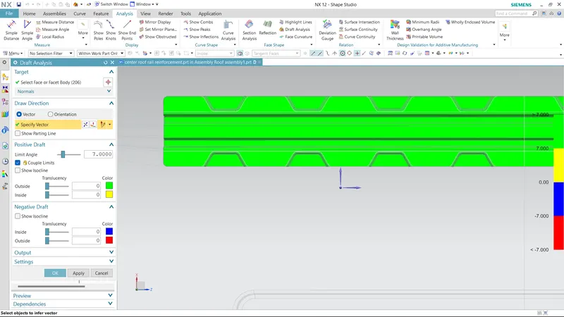
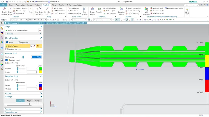
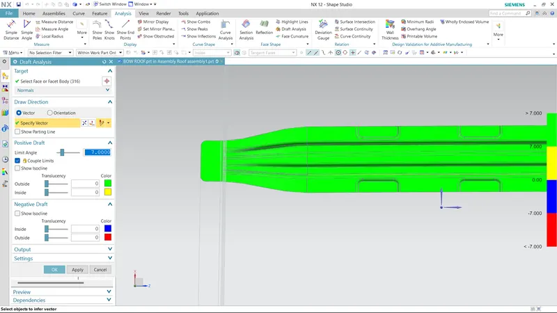
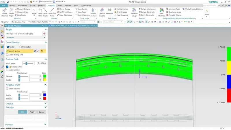
draft analysis:
Front roof rails
Reinforcement center
Center roof rails
Bow roof rails
Rear roof rail
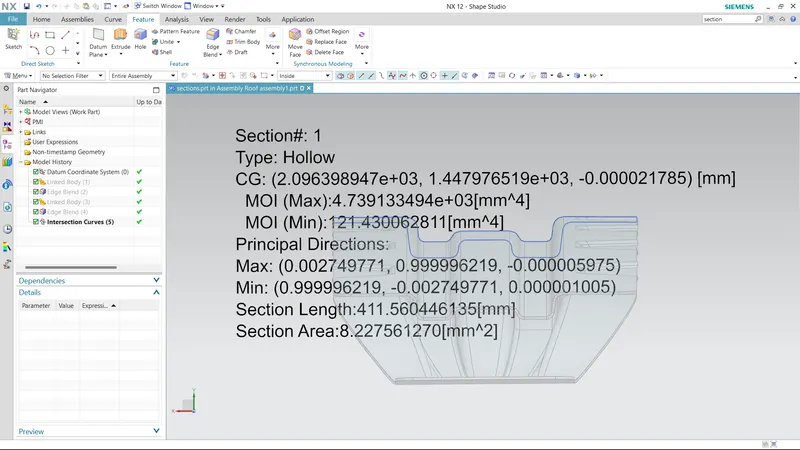
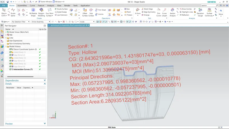
section analysis
CURVATURE STUDY:
Bow–Roof Prediction Formula
W = [1.73 x 10^(-3) x L] + [1.85 x 10^(-8) x (R^2)/t] + [ 1.10x10^(-3) x l] - 2.68
Where,
L = Roof Length in X-Direction[mm](Roof dimension in 0-Y)
R = Roof curvature
R = 2(Rx*Ry)/(Rx+Ry)
Rx = X curvature
Ry = Y curvature
t = Roof plate thickness [mm]
l = Bow Roof Span [mm]
Judgment Condition
OK< 2.7
|
SN.O |
BOW |
Rx |
Ry |
R |
I |
L |
T |
(R*2)/t |
w |
w<2.7 |
|
1 |
FRR – CRR |
5469.3 |
4079.1 |
4672.99 |
810.6 |
2029.9 |
0.75 |
12461.3 |
1.72 |
pass |
|
2 |
CRR – BOW1 |
4041 |
10546.3 |
5843.1 |
472.6 |
2029.9 |
0.75 |
15581.6 |
1.35 |
pass |
|
3 |
BOW1 – RRR |
3295.2 |
16088.3 |
5470 |
362.1 |
2029.9 |
0.75 |
14586.66 |
1.23 |
pass |
Snow Load Prediction Formula
Qr = [Iy x t2] / [α x s x [(Rx + Ry)/2]2 x 10-8]
Note: The Qr value given over here is correct. There was a typo error in the formula given in the video.
Where,
α = My x Lx2 x 10-12 , My = Y(Ly-Y)
t = Roof plate thickness [mm]
Ly = Distance between the front and rear roof Rails on the Vehicle along with 0Y[mm]
Length of Roof panel with the center point between Roof rail Front /Rear as the front and rear reference point.
Lx = Distance between the Left and Right end of the roof on the Roof BOW [mm]
The width of the roof panel is exposed on the surface.
Y = Distance front Front Roof Rail to Roof BOW[mm]
s = Distance for which Roof BOW bears divided load [mm]
s = L1/2 + L2/2
Iy = Geometrical moment of inertia of Roof BOW (Y cross-section )[mm4]
Rx = Lateral direction curvature radius of roof panel Y cross-section on Roof BOW [mm]
Roof panel curvature Radius of the Length Lx in Front view
Ry = Longitudinal Direction curvature radius of the Roof panel X cross-section on Roof BOW [mm]
Roof panel X curvature radius of length s in Side view
Judgment condition
Qr ≥ 3.1
250 ≤ s ≤ 380
| SN.O | BOWS | Iy | lx | ly | y | My | s | Rx | Ry | t | Qr |
OK/NG |
| 1 | FRR & CRR | 121.4300 | 1188.5 | 2029.9 | 913.4 | 1019811.1 | 730.35 | 3912.2 | 4013.8 | 0.75 | 3.6670 | OK |
| 2 | CRR & BOW | 51.309 | 1188.5 | 2029.9 | 547.3 | 811426.98 | 517.05 | 4236 | 10579.8 | 0.75 | 3.5110 | OK |