Radar Mast & Final Assembly of Yacht
Sunseeker Predator yacht report
OBJECTIVE:
- The main objective is to create solid modelling, and surface modelling of different parts in Sunseeker Predator yacht.
- How to assemble different parts of the Sunseeker Predator yacht
- Creating a rendered image using Photo View 360.
Software’s used
- Solid works 2021
- Solid works visualize 2021
INTRODUCTION:
Sunseeker Yachts' legacy began in the 1970s on the British south coast in Poole, England. Formally known as Poole Power Boats, Sunseeker was founded by Robert and John Braithwaite.
Yacht is a Watercraft used for pleasure or sports. The term originates from the Dutch word yacht (which means "hunt'), and originally referenced light, fast sailing vessels that the Dutch Republic navy used to pursue pirates and other transgressors around and into the shallow waters of the Low Countries. The yacht was popularized by Charles II of England as a pleasure or recreation vessel following his restoration in 1660.
Today's yachts are almost exclusively for leisure A yacht is any sail or power vessel used for pleasure, cruising, or racing. The word often connotes luxury; however, luxury is not a quality necessary to meet the definition, nor is it always desirable. Many racing yachts are stripped out vessels with a minimum of accommodations to lower weight. The term 'sailboat' or 'sail yacht' is used in America to differentiate from a powerboat' or 'power yacht' As of December 2018, there were about 6,500 yachts over 24m on the market.
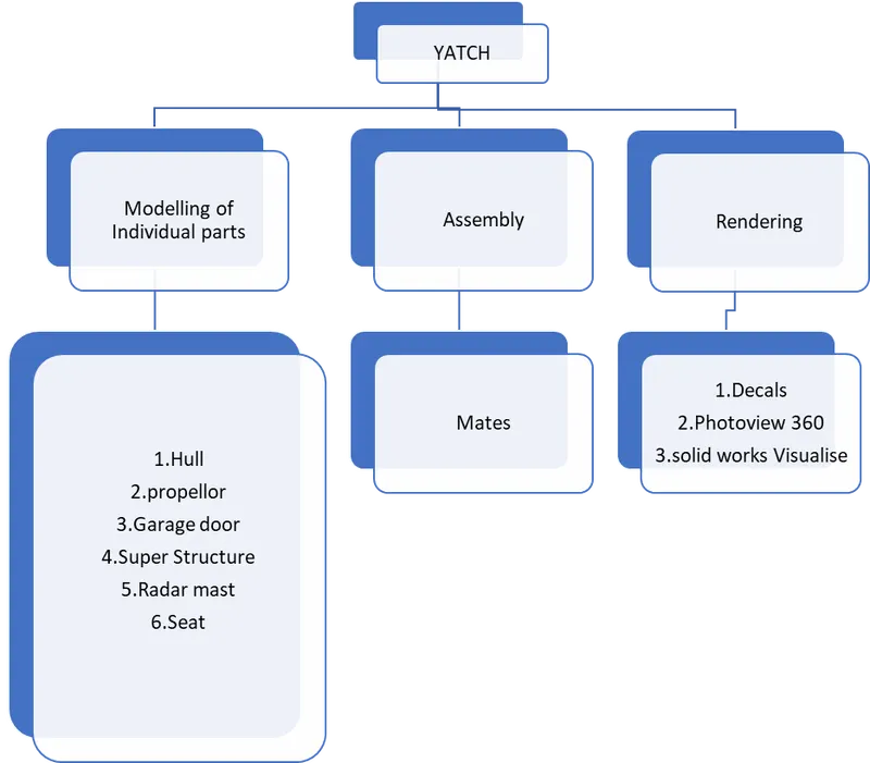
Design methodology flow chart
Design Process
The entire modelling process is divided in to Six Stages
- Blue Print Setup & Creating Planes.
- Modelling of Hull Part
- Modelling of Super Structure
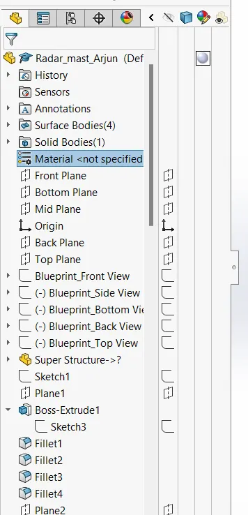
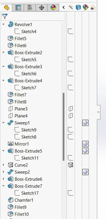
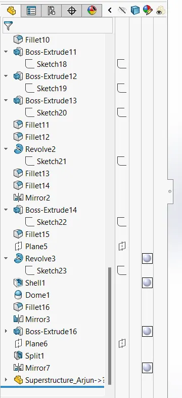
- Modelling of Radar Mast
- Modelling of front, middle & Rear Seats.
- Assembling the individual parts.
Description
Blueprint
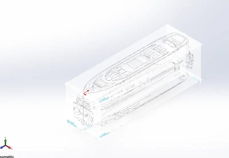
Blueprint is basically a design plan or technical drawings of different orthographic views of a product. The main motto of the blueprint is to bring out the exact same shape and form of the product as designed by a designer. It also the accuracy and the proportion of the product. Designing a product without a blueprint may lead to multiple errors, unnatural proportions and improper dimensions. A proper blueprint setup omits all those problems. To set up a blueprint, we use sketch mode in SOLIDWORKS in each plane. In this case, the images provided for the front view, side view, top view, back view, and top views are added in respective planes. One very important thing to note while setting up a blueprint is the size of it. all the parts are going to be designed laying up the blueprint and taking its reference, it is very crucial to maintain the correct and real size of the blueprint in the very first step. It can either be adjusted manually with the dimensions or by adjusting the scale bar.
TOOLS AND FEATURES:
- Sketch tool.
- Sketch pattern Convert entities
- Offsets entities
- Extrude Boss/Base
- Revolved Boss/Base
- Sweep Boss/Base
- Circular pattern
- Extrude cut
- Fillet/chamfer. Shell
- Reference plane
- Projected curves
- Extrude surface
- Swept surface
- Lofted surface
- Fill surface
- Offset surface
- Ruled surface
- Knit surface
PROPELLER
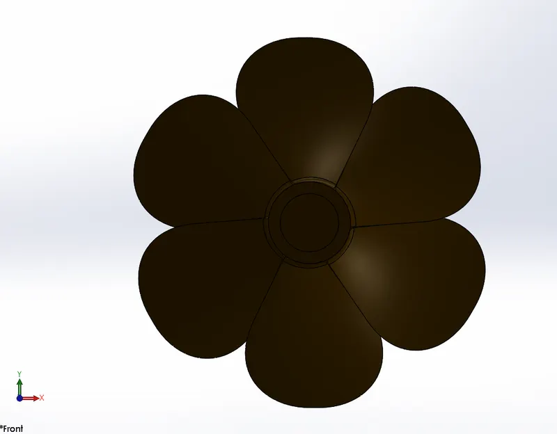
A propeller (colloquially often called a screw if on a ship or an airscrew if on an aircraft), is a device with a rotating hub and radiating blades that are set at a pitch to form a helical spiral, that, when rotated, exerts linear thrust upon a working fluid, such as water or air.
TOOLS USED
REVOLVE/BOSS
This feature helps to revolve the open sketch as well as closed sketch with the help of one axis.
LOFT EXTRUDE
Surface generated by existing edges creating a smooth tangent between the selected curves.
FILLET
Fillets are used to create a smooth curve on the profile or at the edges. For this constant size, fillet is used.
CIRCULAR PATTERN
For this feature one selection of face is required and selections of equal spacing with required angle and number of instances.
EXTRUDE CUT
This is used to remove the material from the solid model with the required depth or draft.
RADAR
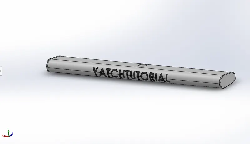
RADAR or Radio Detection and Ranging, is used to detect objects and their position relative to your current location. RADAR acts as a major navigation aid for boaters. It helps in detecting boats, birds, landmasses, and weather systems even if the visibility is less than usual.
TOOLS USED
EXTRUDE BOSS/BASE
This feature is used only when the sketch is closed and then extruded to the required height.
FILLET
Fillets are used to create a smooth curve on the profile or at the edges. For this: constant size fillet is used.
EXTRUDE CUT
This is used to remove the material from the solid model with the required depth or draft
SKETCH PATTERN
In this feature selection of faces is required to create multiple faces by selecting 2D sketches.
MIRROR
This is the replica of one solid body by selecting a plane or by the solid body face. In this mirror, it has an option to create as a single body and to knit it.
EXTRUDE CUT
This is used to remove the material from a solid model with the required depth or draft.
HULL
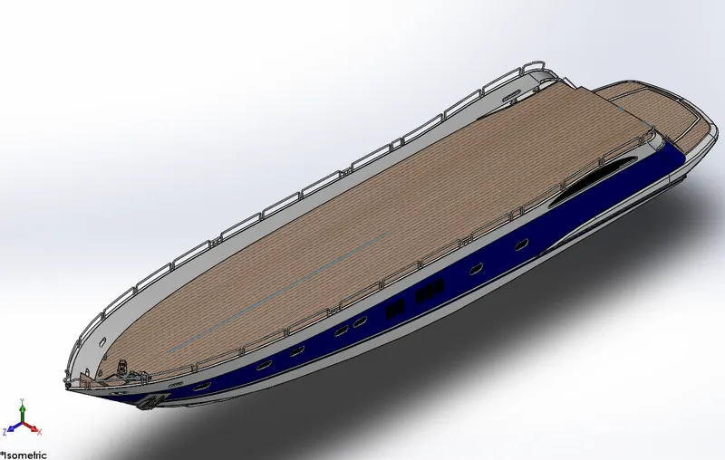
A hull is the watertight body of a ship, boat, or flying boat. The hull may open at the top, or it may be fully or partially covered with a deck. Atop the deck may be a deckhouse and other superstructures, such as a funnel, derrick, or mast.
Methodology
- Blue Print setup - Insert all views like Top view, Side view, bottom view, front. view, etc. by giving proper X, Y & Z Create two new planes Back Plane and Top Plane using Front & bottom plane as references, direction.
- Bottom Plane - Draw a Horizontal line and a spline with midpoint, give relations and dimensions to make it fully defined dimensions to it.
- Mid Plane - Draw an Inclined line , vertical centre-line and a spline blue print Create a Projected curve using above two sketches with 2 midpoints, drag the arrows to make sure it matches
- Similarly create one more projected curve by drawing sketches on Mid plane & Bottom Plane using lines and splines
- Back Plane - Draw a spline and use pierce relation to connect with projected curve.
-Mid Plane - Draw one more spline and use pierce relation again. Now create a lofted surface using above two sketches
- Similarly create one more surface loft by drawing sketches on Midland and Back Plane using splines. - In order to trim extra surface, draw a vertical line in Mid plane and trim extra portion
-Mid Plane - Draw a spline parallel to surface loft and do surface loft. - Mid. Plane Draw a horizontal line and vertical line do surface extrude.
- Trim Extra surfaces a knit them together
- Make sure all lines turn out to black colour which indicates proper knitting - In order to fill the gap use Filled surface by drawing a sketch on Mid Plane
- Now Knit Surfaces and create Shell.
- Mid Plane - Offset created surface entities inwards and draw a line to make closed
- surface. Trim extra entities using Trim entities and extrude it
- Bottom Plane - Draw a sketch using 2 splines and do cut extrude. Apply Fillets: and Chamfers to respective edges.
- For Side Windows - Draw four lines as a rectangle on Plane 1 and apply fillets to corners, do linear pattern. Remove extra created Window & do cut extrude and create cut extrude
- For Port holes - Draw a straight slot on Plane 1, copy the slot to another port hole using copy feature as per blue print Create a 2D Sketch in new plane by drawing a circle and for profile create a 3D Sketches by converting sweep. Repeat similar steps for creating remaining forth holes.
- For Lower Deck - Create a sketch on Top Plane as per Blueprint using Splines, lines and do extrude, forth holes entices.
- Staircase - Crest a sketch on Top Plane by drawing line in rectangle shape and do cut extrude. Select the extruded right face create a solid and draw few connecting horizontal and vertical lines in the form of stairs, extrude it Up-to next/Up-to surface.
- For Lower Portion of Hull - Create a plane at an offset of 3000mm from. Bottom Plane Draw 3 splines and drag their arrows to match as per blueprint Offset the splines and make it closed by drawing lines, extrude it.
- Anchor House - Draw a sketch on Top face of Hull using two circles and connect them with lines and trim the inner half of circle to create a lower surface of Anchor house. Draw a vertical line & horizon line on new plane using previous sketch as reference and revolve it. Create a sketch by drawing lines and circles, extrude it. To remove some portion from previous, extrude, create a sketch and do cut extrude.
- For Rope - Draw a helix and create a plane using helix as reference, draw a circle at the end point of helix. Using Helix as path and circle as profile do sweep. Create one more sweep to connect the rope from house to created helix - Create some extra forth holes at front end and rear end with the help of few sketches and extrude them, use linear pattern accordingly to pattern them
- For Hand railing - Create a new plane offset from left face of stair connected portion Draw a sketch by 3 Point Center rectangle and apply fillets to two top corners. Create one more plane using lower left end point of rectangle and draw a circle Now Sweep using Circle and rectangle as profile & path respectively.
- For Side Railing - Draw a sketch on Mid Plane by offsetting inner edge of Hull inwards and outwards respectively. Draw few vertical lines as per blue print and trim the unwanted portion, so that it will form a chain, apply fillets to end portion and draw one more sketch in respective plane were offset the inner edges of hull Now create a projected curve using above two sketches. Create a new plane at the end of created sketch for railing reference and draw a circle sweep by using circle and projected curve.
- For Calliper - Draw a sketch on Back Plane using few lines and extrude it, to develop calliper surface. Select the surface of Calliper draw a sketch as per blueprint & revolve it.
- For Propeller Shaft - Create a sketch on Back face of Hull by drawing lines as per blue print and revolve it Pattern it accordingly with the help of Pattern direction sketch.
- For Connecting Rod - Draw a 3D Sketch using line to connect both Propeller shaft holes & extrude it.
- For Anchor - Draw a sketch on Mid plane at front portion of Hull using lines and splines as per blueprint and extrude it and mirror it across respective face
-For Garage Door - Draw a sketch on Mid plane by drawing a comer rectangle & do cut extrude, sketch extrude left face and sketch on it by converting previous sketch as entities create cut extrude. Now use split and remove the appropriate portion and save it as Garage door.
- Create a pin by drawing circle on previous extruded face, extrude it.
-Create a new sketch on Mid Plane by drawing Splines and offset in upward and downward direction. Use Split line and select all faces to split.
- Now give appearance to Hull, windows, Railings, Caliper, Anchor,etc.,
- Finally mirror the whole body across. Mid Plane and check all appearance are applied correctly.
TOOLS USED
PROJECTED CURVE
This sketch is used as a 3D curve on the profile. This curve can be achieved by two different line or splines which starts from same direction and ends in the same direction with two different planes.
SURFACE LOFT
This will not create any solid body It creates only 0 thickness profile by selecting the line or spline as profile and guide curve.
SURFACE TRIM
Feature is applicable only for surface modelling not for solid modelling. It trims on the surface with the help of sketch entities only.
SURFACE EXTRUDE
With an open sketch also the surface: extrude can be done, it need not be a close sketch. Again, this feature works with surface modelling only
KNIT
Knit is used to reduce the gap between the two surfaces
SURFACE FILL
Surface fill is similar to surface loll
SHELL
Shell is used to create a hollow profile by selecting the face or body with the
required thickness
EXTRUDE CUT
This is used to remove the material from the solid model with the required depth
of draft.
EXTRUDE BOSS/BASE
This feature is used only when the sketch is closed and then extruded to the required height
FILLET
Fillets are used to create a smooth curve. on the profile or at the edges. For this constant size, fillet is used.
MIRROR
This is the replica of one solid body by selecting a plane or by the solid body face. In this mirror, it has an option to create as a single body and to knit it.
Garage door
A closed boat garage can provide better protection from the elements, birds, and burglary activity as well.
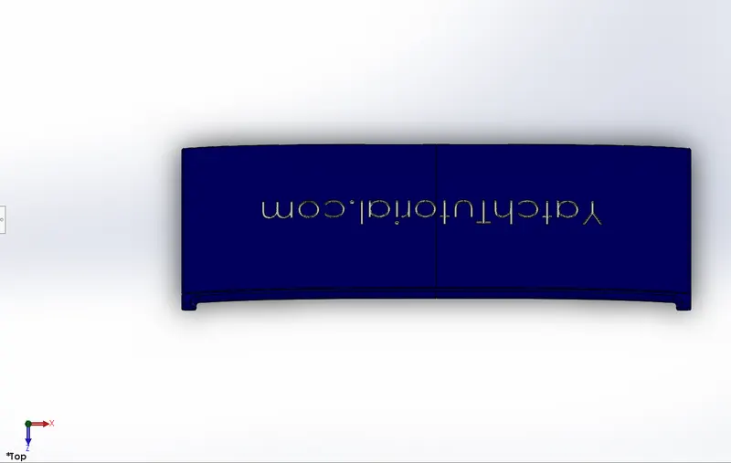
It's a door for the Garage. A garage door is a large door on a garage that opens either manually or by an electric motor (a garage door opener). Garage doors are frequently large enough to accommodate automobiles and other. vehicles. Small garage doors may be made in a single panel that tilts up and back across the garage ceiling.it was created out of the split ed block from the Hull. It is provided with two holes to adjust the pins in order to open or close the garage door. It encloses the garage. space which can accommodate a locomotive inside it.
Methodology
Open Garage Door part which was saved while designing Hull part Create a sketch a right face of Stock by drawing lines and do cut extrude
- Apply Shell by selecting faces of the stock
-Draw a circle at the top by selecting side face of stock and do cut extrude to create a hole.
- Apply fillets & mirror across Right Plane.
- Create a plane using Front Plane as a reference by offsetting it. - Draw a sketch on created Plane by drawing Horizontal Centre line and insert Text in Text box, do cut extrude.
- Finally give Appearance to Door and Text.
FRONT SEAT
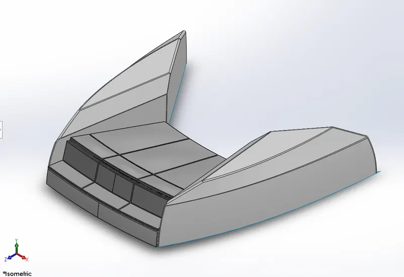
Marine passenger seats and chairs can be used on the fast ferry, high-speed passenger ship, cruise ship, catamaran, crew boat, cargo ship, the sightseeing boat, traffic boat, pilot launch, yacht and other passenger vessels. The material of the seats adopts fire-proof leather, PU/PVC leather or fabric according to customer's requirements. The anti-corrosion aluminium structure is durable.
Methodology
- Blue Print setup - Insert all views like Top view. Side view, bottom view, front view. Etc. by giving proper XY & Z direction. dimensions to it.
- Create two new planes Back Plane and Top Plane using Front & bottom plane as references.
- Create Swept Surface by creating a sketch on Deck face by drawing a spline & another sketch on created plane by drawing a line. - Draw two lines and connect with previously created surface. sweep and extrude the surface.
- Trim the Extra surface and fill the gap portion with Filled Surface.
- Draw few sketches accordingly to trim extra surfaces.
- Create Surface loft using above two sketches. Knit it together.
- Trim the Extra surfaces & Draw lines accordingly to create seat and revolve it about 10 degrees.
- Apply Fillets and mirror the bodies.
- Finally Apply Dome to seats & give appearance.
TOOLS USED
SURFACE EXTRUDE
With an open sketch also the surface. extrude can be done, it need not be a close sketch. Again, this feature works with surface modelling only.
FILLET
Fillets are used to create a smooth curve on the profile or at the edges. For this constant size, fillet is used.
SURFACE LOFT
This will not create any solid body It creates only 0 thickness profile by selecting the line or spline as profile and guide curve.
SURFACE TRIM
Feature is applicable for surface modelling only not for solid modelling. It trims on the surface with the help of sketch entities only.
KNIT
Knit is used to reduce the gap between the two surfaces.
REVOLVE/BOSS
This feature helps to revolve the open sketch as well as closed sketch with the help of one axis.
SURFACE SWEEP
It is the same as sweep boss but in surface modelling surface sweep is used by selecting the profile and the part for the sweep.
DOME
This creates a smooth tangent curve on the face of the body.
MIDDLE SEAT
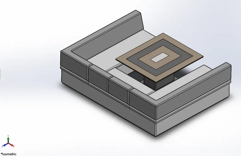
The middle seat is situated in middle of the deck surface.
Methodology.
- Blue Print setup - Insert all views like Top view, Side view, bottom view, front view, etc.by giving proper XY & Z direction dimensions to it.
- Create two new planes Back Plane and Top Plane using Front & bottom plane as references.
- Insert the Hull part by selecting the surface bodies.
- Draw a L Shape using lines on face of deck and extrude for lower portion of seat.
- Create a sketch on above extrude face offset the face and extrude. Create a Plane on above extrude face by offsetting at a distance of 5mm. Sketch on it by drawing lines as per blueprint and extrude.
- Mirror the bodies across Mid Plane by selecting Knit Surfaces and merging solids.
- Mirror seats across Mid Plane by De selecting Knit Surfaces and Merging. solids.
- Create a Table by selecting deck face using lines and offset entities.
- Create a Cut Extrude at the top surface of the table and apply fillets.
- Finally give Appearance to Table & Seats.
TOOLS USED
EXTRUDE BOSS/BASE
This feature is used only when the sketch is closed and then extruded to the required height.
FILLET
Fillets are used to create a smooth curve on the profile or at the edges. For this constant size, fillet is used.
MIRROR
This is the replica of one solid body by selecting a plane or by the solid body face. In this mirror it has an option to create as a single body and to knit it.
EXTRUDE CUT
This is used to remove the material from the solid model with the required depth or draft.
REAR SEAT
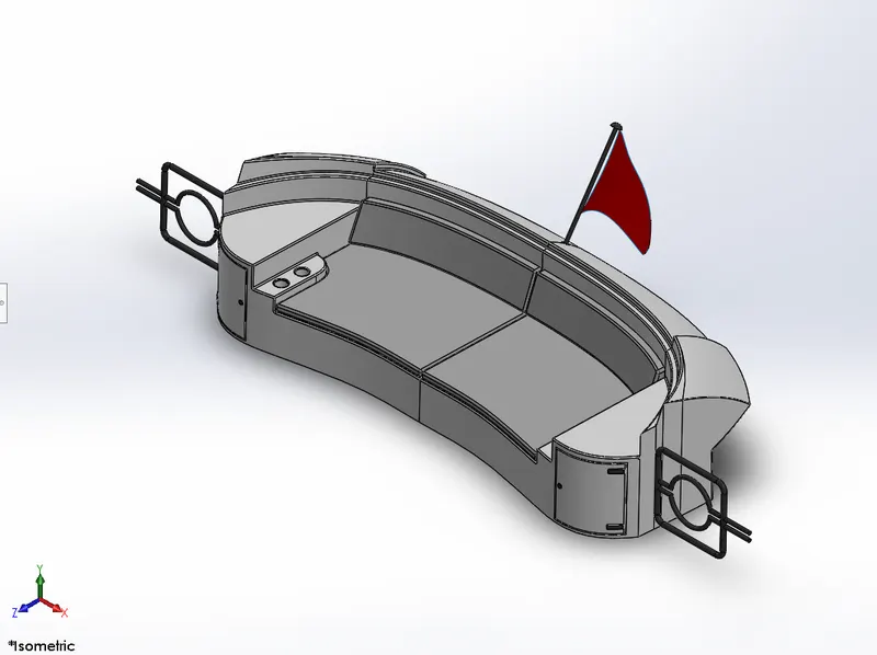
The rear seat is situated in back end of the deck surface and it attached with flag.
Methodology.
- Blue Print Setup-Insert all views like Top view, Side view, bottom view, front view, etc. by giving proper X, Y & Z direction dimensions to it. - Create two new planes Back Plane and Top Plane using Front & bottom plane as references,
- Insert the Hull part by selecting the surface bodies. - Mid Plane - Draw 2 Splines as per Blueprint dimension it to make fully define.
- Create a Plane using Deck face & vertex of spline as references. - Create one more sketch on new plane by drawing a spline.
- Now using above two sketches do Surface Sweep.
Create an offset surface of previous sketches by selecting respective faces. Trim the Extra Surface by drawing sketches accordingly.
- Use Ruled Surface to extend the surface: and knit everything. - Draw a sketch on Plane 1 using Splines which is used to trim surface.
- Create few Planes and draw sketches by causing convert entities and splines. Do Surface sweep using these sketches - Extend the Surface and trim the unwanted surfaces using surface trim and knit them.
-Create few 3D Sketches and do surface loft.
- Create a sketch on deck face by converting respective entities and spline with midpoint, extrude it - For Hand resting - Create a Sketch on Previous Extruded face by selecting face and convert entities. Draw few lines as per blue print and trim extra entities, Extrude it.
- For Doors/Drawers - Create a cut extrude by drawing a line on Front Plane,
- Offset the appropriate faces for creation of Seats in the surfaces by keeping the selection to split the surfaces.
- For Upper Seats - Create a Boss Extrude by drawing Sketch on offset surface using convert entities and line. Apply Chamfer and fillets accordingly.
- For Lights - Create a sketch on Plane 4 by drawings and extruding line. - For Locking Gates - Create few planes as per requirement and draw sketches accordingly using circle and line. Using these sketches sweep and mirror it.
- Mirror the Bodies across Mid Plane by Selecting Knit Surfaces & Merge solids. - Mirror seats and gates across Mid Plane separately by deselecting Knit Surfaces & Merge solids.
- For Flag Stand - Create a sketch on Mid Plane by drawing lines at an angle and revolve it.
-For Flag - Create four 3D Sketches by drawing spline with midpoints in each sketch and loft the surface.
-Finally Give Appearance to Seats, Lower Surface, Flag, Hand resting, Lights, Drawers & Gate.
TOOLS USED
SURFACE SWEEP
It is the same as sweep boss but in surface modelling surface sweep is used by selecting the profile and the part for the sweep.
SURFACE TRIM
Feature is applicable for surface modelling only not for solid modelling. It trims on the surface with the help of sketch entities only.
SURFACE EXTRUDE
With an open sketch also the surface. extrude can be done, it need not be a close sketch. Again, this feature works with surface modelling only.
KNIT
Knit is used to reduce the gap between the two surfaces.
SURFACE LOFT
This will not create any solid body It creates only 0 thickness profile by selecting the line or spline as profile and guide curve.
FILLET
Fillets are used to create a smooth curve on the profile or at the edges. For this constant size, fillet is used.
MIRROR
This is the replica of one solid body by selecting a plane or by the solid body face. In this mirror, it has an option to create as a single body and to knit it.
SURFACE OFFSET
This creates an equal distancing with the selected surface with required. dimensions, this feature is used only in surface modelling.
RULED SURFACE
Ruled surface create a tapered curved surface with the help of a single edge with a specified distance
EXTRUDE CUT
This is used to remove the material from the solid model with the required depth or draft.
EXTRUDE BOSS/BASE
This feature is used only when the sketch is closed and then extruded to the required height.
SUPERSTRUCTURE
A superstructure is an upward extension of an existing structure above a baseline. This term is applied to various kinds of physical structures such as buildings, bridges, or ships.
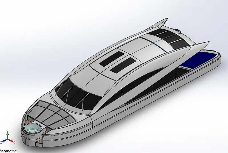
Methodology.
-Blue Print setup - Insert all views like Top view, Side view, bottom view, front view, etc. by giving proper X, Y & Z direction
- Create two new planes Back Plane and Top Plane using Front & bottom plane as references.
- Insert the Hull part by selecting the surface bodies.
- Create a sketch on Deck Surface by drawing a two Splines and a line as per blueprint and extrude the surface.
- Create a Plane at the end of Create surface Extrude.
- Create a surface sweep by drawing sketches on created Plane using line (Horizontal) and apply pierce reaction with extruded sketch by convening Outer surface as entities. - Extend the Outer edge of surface using Ruled surface at an angle and trim the extra surface. Knit all the surfaces dimensions to it surface.
- Create more Projected Curve by drawing-two sketches on respective Planes using Splines and lines which is further used in creating Lofted Surface
- Create one more surface sweep by drawing sketches on created Plane using line (Horizontal) and apply pierce. reaction with extruded surface. A 3D sketch by convening Outer surface as entities.
- Trim the surfaces which are not required by drawing sketches on respective faces/Planes.
- Create a Swept Surface by drawing at sketch-Trim the extra surfaces on Midi Plane using Splines and a 3D Sketch by converting respective edges.
- Similarly, for creation of surfaces on Top, draw two sketches on respective Planes to get Projected Curve as per blue print which is further used to create Lofted Surface.
- For Side Windows Select the outer surface of Super structure use Ruled surface for extension. Trim the Extra surfaces.
- Select the Deck face and create a sketch by drawing a line at rear portion and do Surface extrude. Trim extra surfaces and knit all together.
-For Front Portion - Draw a sketch on Mid Plane by converting respective edges and do surface extrude. Trim extra surfaces and knit all there to. Create one more sketch on Mid Plane by drawing line and spline and do surface extrude.
- Select the deck surface and create a sketch by drawing a circle at a distance from above surface extrude. Extrude it and draw a circle at on extruded face to perform cut extrude. Draw two more circles on extruded face which are again to be extruded. Apply fillets to respective edges. In order to remove extra portion, draw a rectangle. on deck surface do cut extrude. Use Delete face option to remove respective faces.
- For Steps: Draw few lines horizontal and vertical lines accordingly and extrude them. Trim the Extra Surfaces.
- In order to make it Solid, Sketch on deck Surface by drawing line and do surface extrude. Trim the extra surfaces and Create Solid by knitting the surfaces.
- For Mattress - Create a Surface Offset at Front end and Trim unwanted surface. and thicken the surface by selecting respective faces. Create a cut extrude and apply domes and fillets to them.
For Railing (Side and Front) - Create a sweep by drawing sketches on respective planes using circle and splines. - For Door (at Rear end) - Create a cut extrude by offset rear face inwards. Draw a L shape and extrude it for handle creation
- For Front Glass- Create a Sketch on Top Plane by Offset entities and do cut extrude
-For Frames - Sketch on respective face by drawing two vertical lines and converting top and bottom edges of glass. Trim unwanted entities and do Extrude
- For Top Glass- Create a sketch on Top Plane by drawing a line and Spline and do cut extrude - For Top Frames - Create a sketch by offset introspective edges and remove unwanted entities using Trim entities. Extrude it Similarly create windows and frames for side faces by drawing few sketches and doing cut & Boss extrude respectively - For Rear portion, draw a sketch on Mid plane Offset respective face and do split line.
- For Wipers Holders - Create a Sketch on top face of Super structure by drawing one circle and half circle. Extrude them.
- Mirror the bodies across Mid plane.
- For Radar Mast Reference - Create a Offset Surface by selecting rear portion of Top face of Super Structure and rename it
- For Wipers - Create a respective plane and do Boss extrude. Repeat two more times at respective places. Apply Chamfer and offset the Side faces and do cut extrude. Similarly do it for remaining Wipers. Draw 3D sketch by drawing a line connecting holder and wiper, extrude it which acts a connecting rod. Repeat for remaining ones.
- Give Appearance to windows, Doors, Frames, Mattress, Wipers, water, Railing and Superstructure.
TOOLS USED
SURFACE EXTRUDE
With an open sketch also, the surface extrude can be done, it need not be a close sketch. Again, this feature works with surface modelling only.
SURFACE SWEEP
It is the same as sweep boss but in surface modelling surface sweep is used by selecting profile and the part for the sweep
KNIT
Knit is used to reduce the gap between the two surfaces.
FILLET
Fillets are used to create a smooth curve on the profile or at the edges. For this constant size, fillet is used.
SURFACE LOFT
This will not create any solid body It creates only 0 thickness profile by selecting the line or spline as profile and guide curve.
SURFACE TRIM
Feature is applicable for surface modelling only not for solid modelling. It trims on the surface with the help of sketch entities only.
RULED SURFACE
Ruled surface creates a tapered curved surface with the help of a single edge with a specified distance.
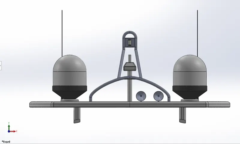
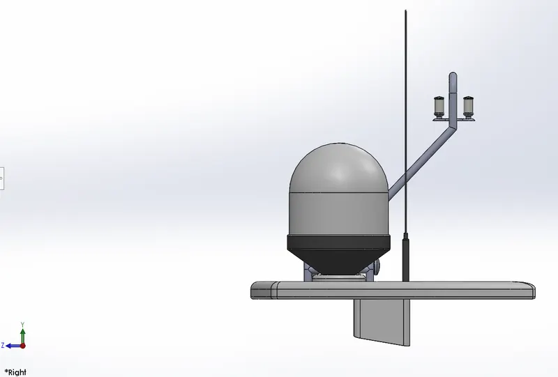
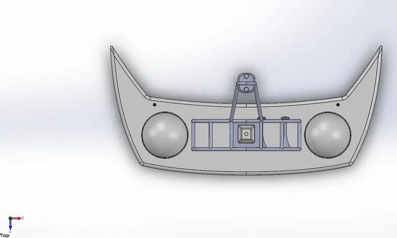
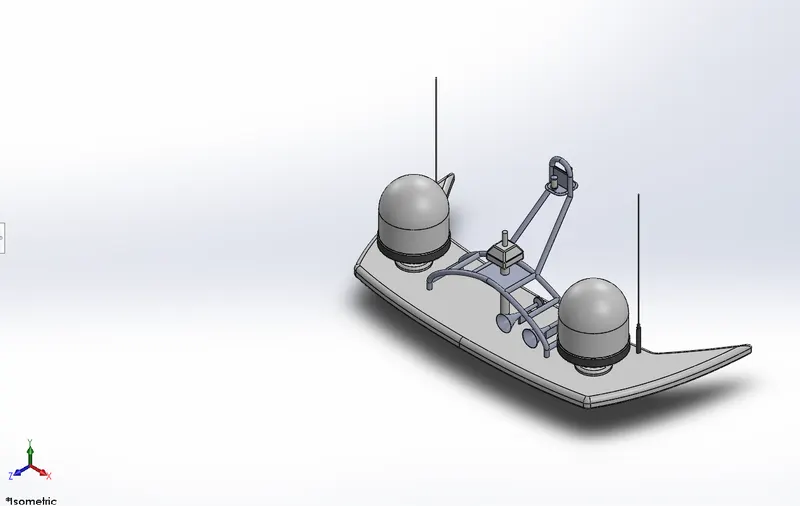
RADARMAST
They are electronic navigation instruments that use a rotating antenna to sweep a narrow beam of microwaves around the water surface surrounding the ship to the horizon, detecting targets by microwaves reflected from them, generating a picture of the ship's surroundings on a display screen.
Methodology
- Right Plane - Draw a Trapezium using lines & extrude it.
- Sketch on Face of previous extrude by converting sketch 1 entities & extrude it.
- Sketch on Face of Sketch 1 extrude by drawing a circle at a distance of 60mm from lower edge converted entity & extrude
- Draw a circle on Previous Extrude face and do cut extrude.
- Use Sketch point to locate the previous extrude at required place and do sketch pattern.
- Now mirror across Right Plane.
- Draw a circle at lower edge of Radar face & do cut extrude.
- Sketch on Outer face of Radar using line, insert text as of choice and split across line:
- Finally give Appearance to it.
TOOLS USED
EXTRUDE BOSS/BASE
This feature is used only when the sketch is closed and then extruded to the required height
FILLET
Fillets are used to create a smooth curve on the profile or at the edges. For this constant size, fillet is used.
SURFACE SWEEP
It is the same as sweep boss but in surface modelling surface sweep is used by selecting the profile and the part for the sweep.
DOME
This creates a smooth tangent curve on the face of the body.
REVOLVE/BOSS
This feature helps to revolve the open sketch as well as closed sketch with the help of one axis.
MIRROR
This is the replica of one solid body by selecting a plane or by the solid body face. In this mirror, it has an option to create as a single body and to knit it
SHELL
Shell is used to create a hollow profile by selecting the face or body with the required thickness.
Assembly
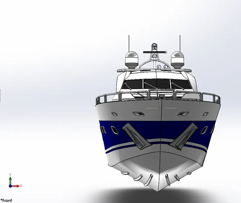
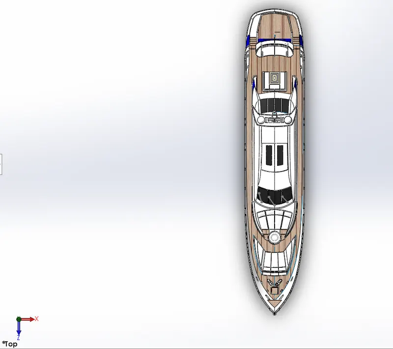
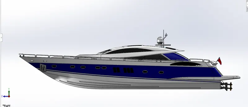
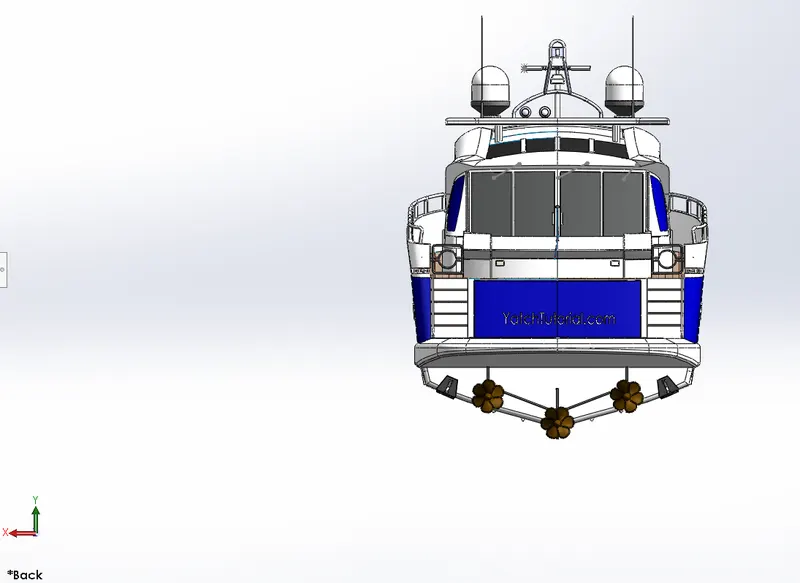
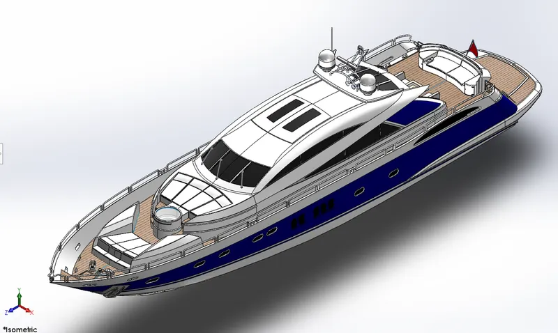
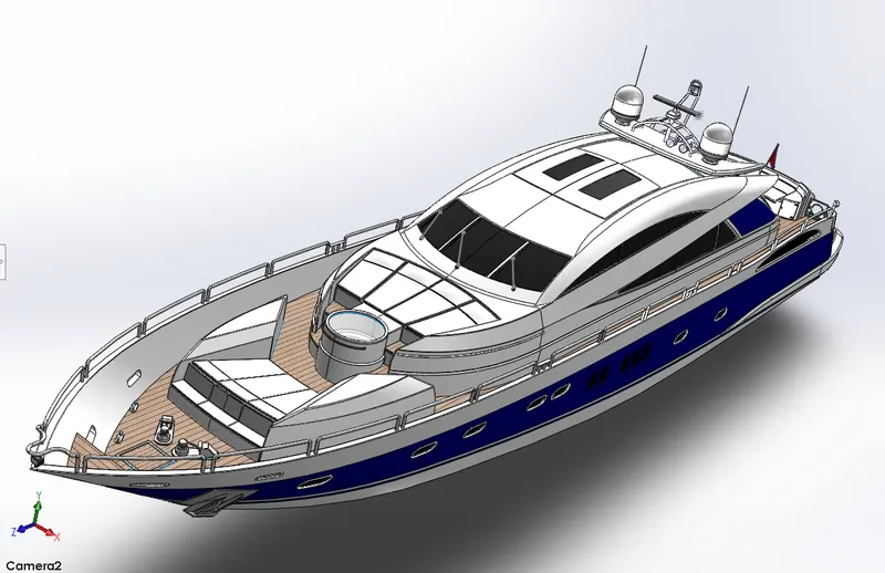
The assembly of the Yacht is quite simple since we have taken the base deck surface for the most of the parts it gets mated automatically although some mates are used to assemble the Yacht.
Mates Used
o Coincident
o Concentric
o Angle Limit
Assembly front view
Assembly top view
Assembly right side view
Assembly back view
Assembly isometric view
Camera view
Steps to be followed for Assembly
- All Designed Parts to be inserted one by one as per requirement.
- Apply Mate Conditions with respective parts for give exact location in Assembly.
- In this assembly Only Rear seat, Radar and Propellers are located using coincident and Concentric relations with respective Parts. Other Parts are already fixed (Using Surfaces as references) so no need of giving separate mate conditions.
Methodology.
- Import-Import assembly once created a new project.
- Appearance - Give appropriate appearances to various parts to make more attractive after rendering.
- Scenes - Use Proper BackPlates/Environment as scenes and drag the assembly at proper location.Decals:
- Graphics or designs used
- Lights & cameras-To adjust lighting and set camera
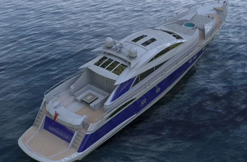
- Output - Once done with all setup, A quick render helps you out to review final output. Changes the colours by increasing/decreasing various values for better look (if required). Then go for final quality rendering
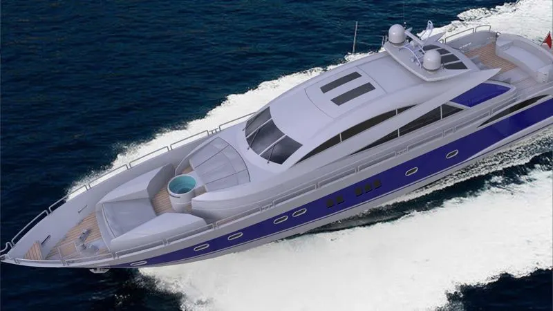
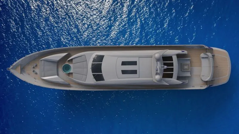
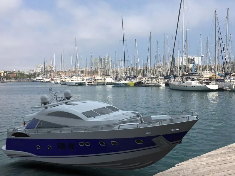
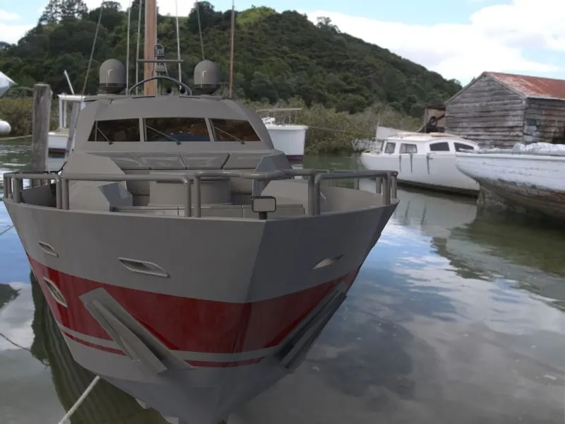
Rendered images
CONCLUSION
To conclude, design, assembly and rendering of the Sun seeker Predator Yacht are done using SOLIDWORKS.