Wiring harness design in CATIA V5 - 3D modeling Week 4 Challenge
AIM
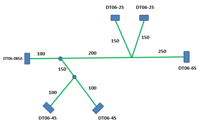
Route the following harness layout in Electrical workbench by using following connectors as shown in layout diagram.
Objectives
- Route the following harness layout in Electrical workbench.
- Make assumption for harness bundle diameters.
- Use Following connectors as shown in layout diagram.
- Add protective covering on all branches connected to DT06-2S & DT06-4S connectors.
- Keep end extremity at 30mm (from connectors end)
Introduction
Given connectors are:
- DT06-4S
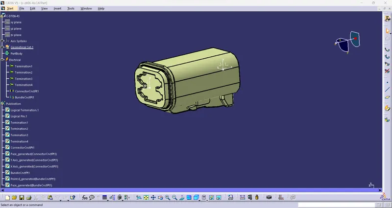
TE Internal #: DT06-4S
TE Internal Description: PLG, 4P, GRY, N
Connector & Housing Type: Housing for Female Terminals
Mating Pin Diameter: 1.59 mm [.063 in] Connector System: Wire-to-Wire
Number of Positions: 4
Centerline (Pitch): 4.45 mm 1.175 in]
- DT06-6S
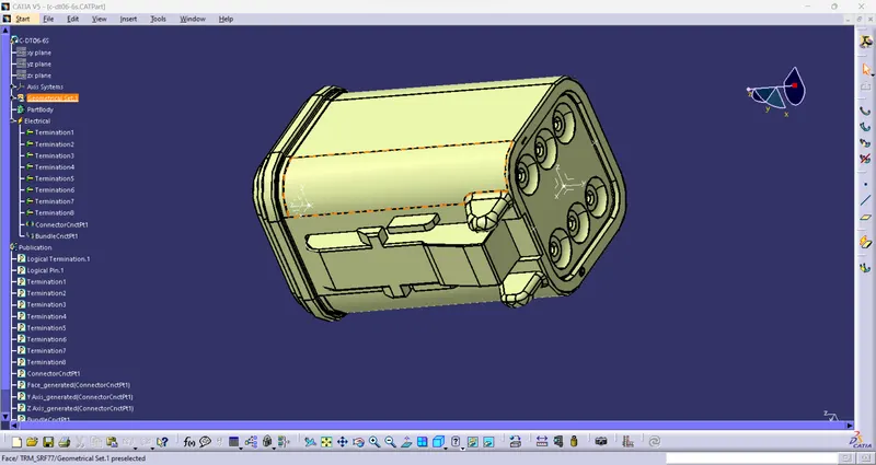
TE Internal #: DT06-65
TE Internal Description: PLG, 6P, GRY, N
Connector & Housing Type: Housing for Female Terminals
Mating Pin Diameter: 1.59 mm [.063 in ]
Connector System: Wire-to-Wire
Number of Positions: 6
Centerline (Pitch): 9.12 mm [.359 in]
- DT06-2S
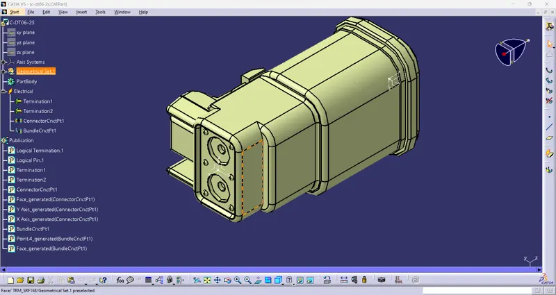
TE Internal #: DT06-25
TE Internal Description: PLG, 2P, GRY, N
Connector & Housing Type: Housing for Female Terminals
Mating Pin Diameter: 1.59 mm [.063 in ]
Connector System: Wire-to-Wire Number of Positions: 2
Centerline (Pitch): 5.46 mm [.215 in]
- DT06-08SA
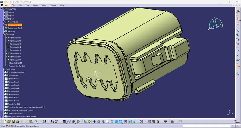
TE Internal #: DT06-08SA
TE Internal Description: PLG, 8P, GRY, N, A
Connector & Housing Type: Housing for Female Terminals
Mating Pin Diameter: 1.59 mm [.063 in]
Connector System: Wire-to-Wire
Number of Positions: 8
Centerline (Pitch): 9.12 mm [.359 in]
Connectors Layout Design:
PROCEDURE
1. Download connectors 3D data from www.te.com
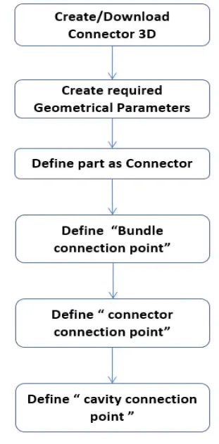
2. Convecting the Mechanical part into the Electrical part for that I had followed
the following steps
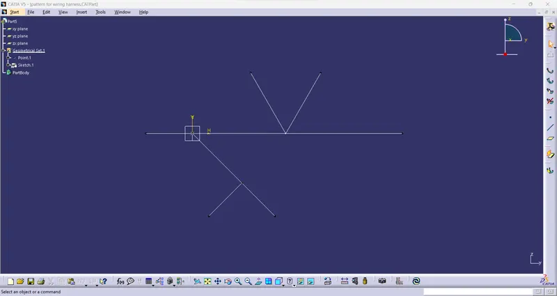
3.Sketch the connector layout on sketcher work bench for referance.
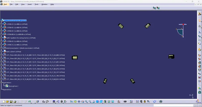
3. Arranging the Connectors by following the Layout.
5.Creating primary multi branching between DT06-08SA and DT06-6S in 10 mm diameter.

6.Creating two multibraching point in the intervel of 100 mm and 200 mm.
7.From the distance of 100mm connect the multi branch between point and DT06-4S in 6 mm wire diameter.
8.Create one more multi braching point in bottom brach at the distance of 150 mm.
9.Insert duplicate of DT06-4S and route between bottom point and connector.
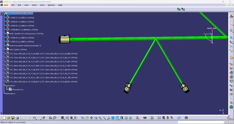
10.Finally Route DTO6-2S connectors with multibranching point which already created in at the distance of 300 mm.The diameter of the wire is taken as 6 mm.
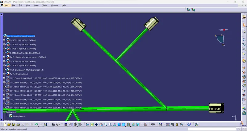
11.Create protective covering using cot tube with end extrimity of 30 mm.
- For primary muti braching 15 mm cot tube is used for protection
- for branches 10 mm cot tubes are used.
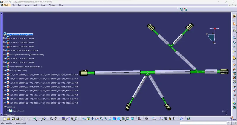
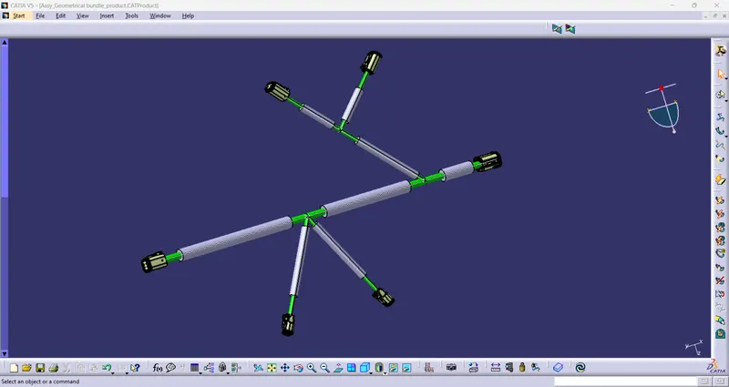
Conclusion
Routed all the connectors as per the layout and provided protective covering.