Week 8 - Challenge 4 - Bumper
BUMPER
Object
- The objective of the project is to carry Draft Analysis by creating the tooling direction for the given Class-A surface.
- Create the class B and C surface for the Bumper with the given Class-A surface to design a component.
Introduction
- INTRODUCTION:
- The Draft Analysis command enables you to detect if the part you drafted will be easily removed from the mould. This type of analysis is performed based on colour ranges identifying zones on the analyzed element where the deviation from the draft direction at any point, corresponds to specified values.
- Tooling direction is the main consideration for plastic part and mould parts because it defines the movement of the mould part and the possibility of the plastic part coming out from the mould part (Core and Cavity).
- A bumper is a structure attached to or integrated with the front and rear ends of a motor vehicle, to absorb impact in a minor collision, ideally minimizing repair costs.
- Consider the thickness of the component 3 mm.
Tooling Axis :-
Tooling axis or tooling direction is main consideration for plastic part and mold parts because it defines movement of mold part and possibility of plastic part to come-out from mold part (Core and Cavity). In Molding machine arrangement is given to open the mold along a direction which is known as Tooling Direction. The mold is built from two separate halves (Core and Cavity) and tooling direction basically define the direction of mold pulls apart. Tooling direction is known as primary direction.
- Open the given CATPART and check for the gaps and boundaries of the component by using boundary option and selecting the whole component. any unwanted gaps in the model will be highlighted easily.
- The tooling axis needs to be created (the direction of the Mold input), perform all the operation in the separate geometrical set an name it accordingly.
- Firstly, create a point in the desired location and between the hole in the component.
- Create a Dummy Tooling Axis with the center point in Z direction.
- Now using the intersection option select the component and the YZ-Plane to create a intersecting lines on the component. Make sure to keep all sub elements.
- Now with the reference on the intersecting lines create another lines using point-point option and extend them accordingly.
- Now create a bisecting- line with reference of the two newly created lines and point
- Bisecting line were used to get the exact medium so that maximum positive draft angle can be achieved.
- Finally by using the bisecting line option the tooling axis were created.
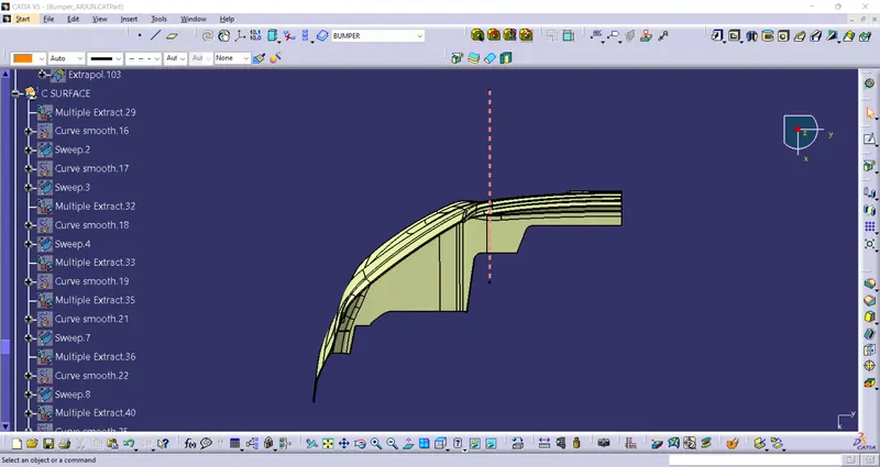
Publication:
- The tooling axis and class-A surface were published for further easy reference.
- What is Draft?
- Draft is providing angles or tapers on product features such as walls, ribs and bosses that lie parallel to the direction of release from the mold eases part ejection.
- Draft allows for the parts to release from the mold.
- Draft is required on all parts in the direction of mold movement in order to allow parts to release or eject form mold properly.
- Draft is the angle in which the parts is tapered to allow it to release. As the part cools, it tends to want to shrink to the core side of the mold.
- Adding draft helps the part to release. Most parts or applications require minimum of 1/2 to 1 degree, however 3 degrees is widely accepted as the norm.
Draft Analysis :-
- For plastic parts, the nominal angle value for draft analysis is 3 degree but even a 0.5-degree angle can be created for sub-assemblies like ribs and slots. (For Sheet Metal 7 degree angle is the nominal value)
- Insert - Analysis - Feature Draft Analysis.
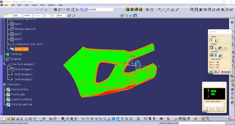
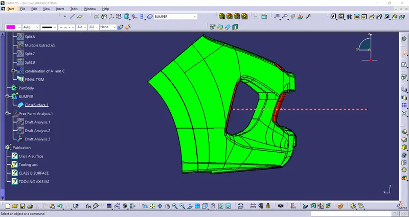
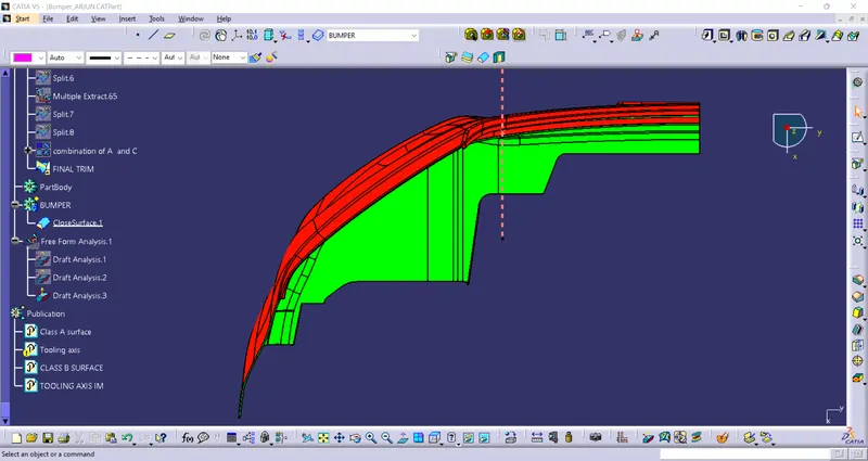
- Draft analysis was carried out by pulling the compass to the tooling axis and an inverse draft axis was carried out if required.
- After setting the compass over the tooling axis the compass must be locked to a specific direction.
- If the surface was in green then the model passes or else further operations need to be carried out.
Draft analysis on class A- surface
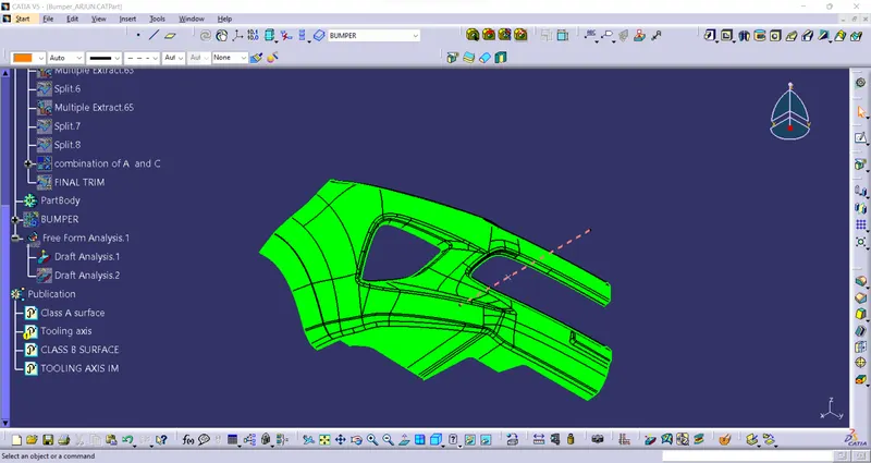
Final draft analysis
DESIGN A COMPONENT USING B & C - SURFACE
Class A Surface :-
In automotive design application Class A Surfaces are created on all visible exterior surfaces (ex; body panels, bumper, grill, lights etc.) and all visible surfaces of see-touch & feel parts in interior (ex: Dashboard, seats, door pads etc.). This can also include beauty covers in the engine compartment, mud flaps, trunk panels and carpeting. This surface has 0 mm thickness.
Class-B Surface:
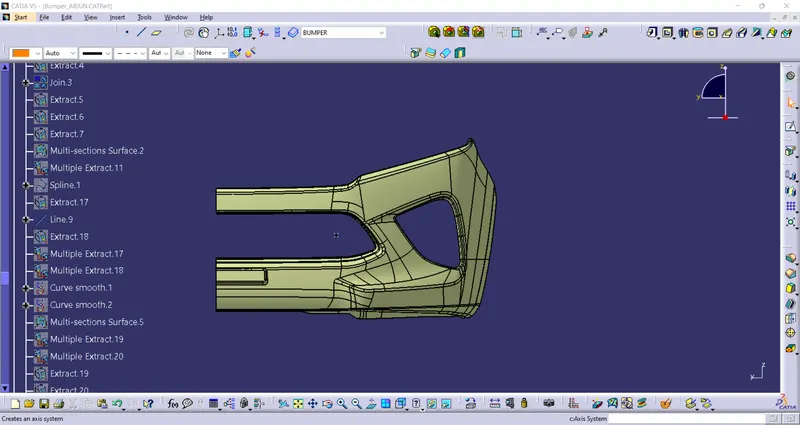
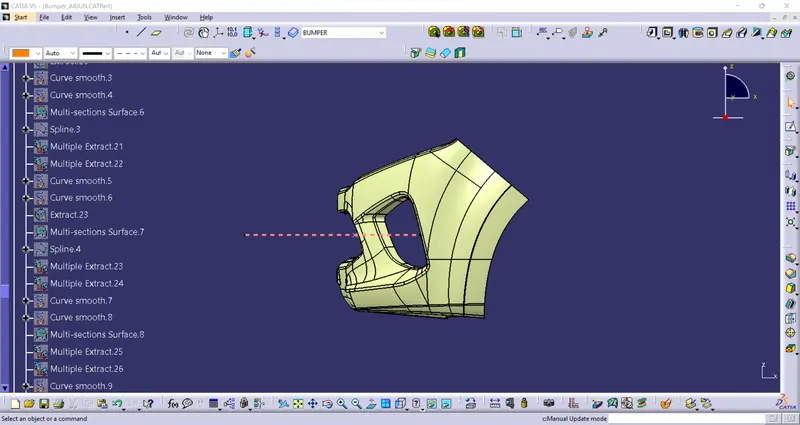
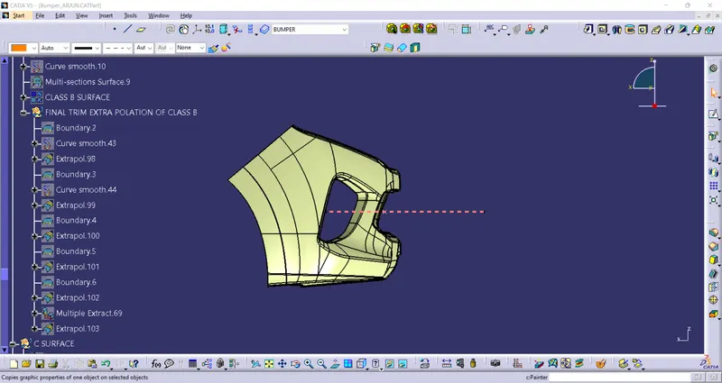
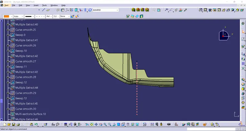
- This surface is created by taking direct offset from class A surface. It is the surface on which all engineering feature like screw bosses, dog house, ribs & mounting are created.
Class-C Surface:
- This is the surface that joins class A & class B together.
After creating class c surfaces this steps will follows:
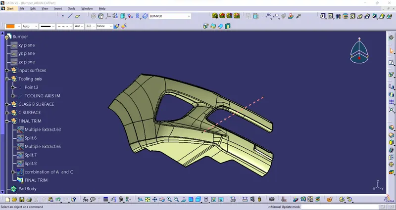
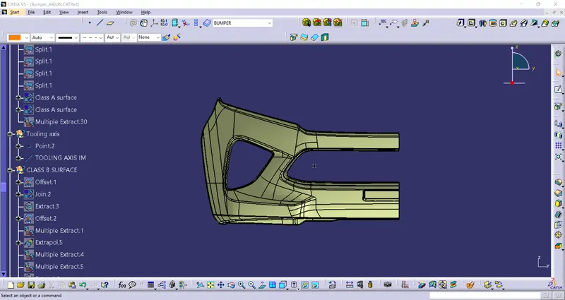
- Joining the Class A & C Surface.
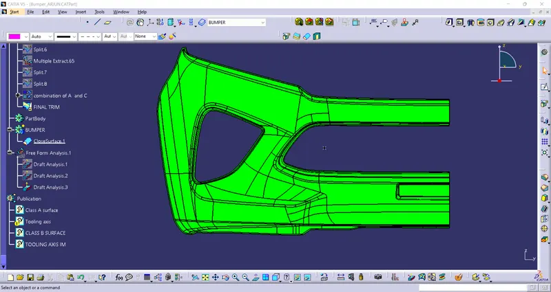
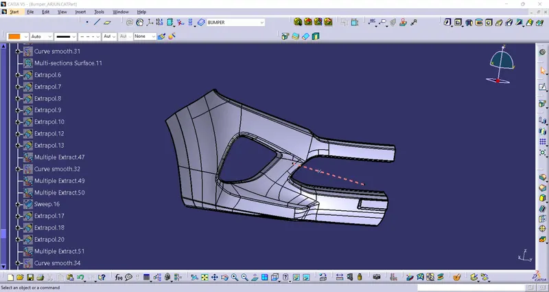
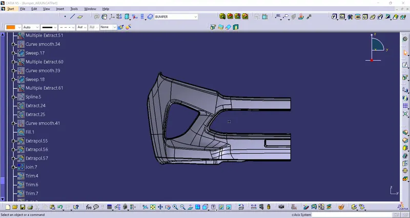
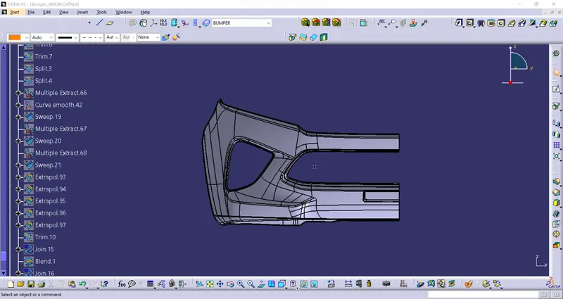
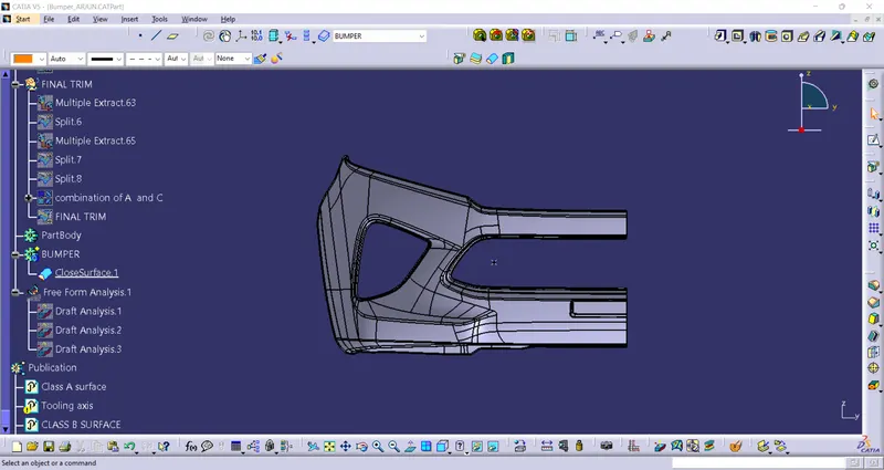
- Trimming the Class B & C surfaces and get the final trimmed bumper closed surface.
- Solid Model is created in part workbench by using Close Surface command.
Conclusion
Created bumper through the given class A surfaces and draft analyzed the surface with 2.9 degree of draft angle.