Roof Design
Aim
Design roof and its reinforcements and analyse with curve study.
OBJECTIVE
- The objective of this project is to design car roof with essential flanges and reinforcements like ditch area, front roof rail, bow roofs, central roof rail and rear roof rail for the the given styling surface.
- Perform a curvature study on the roof and perform the calculations for the heat distortion and snow load criteria to determine whether the bow roofs are at the correct positions.
- Finding moment of inertia and section modulus for Bow roofs, central roof rail,front roof rail and rear roof rail.
- Perform the draft analysis for each reinforcements.
Roof Design
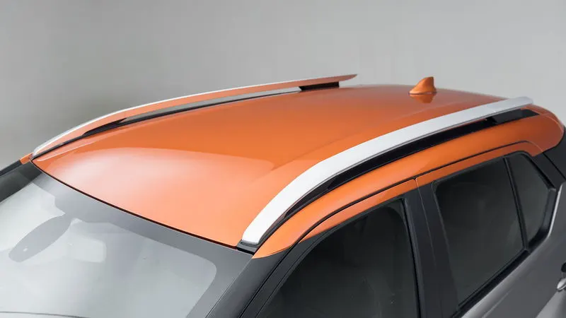
A roof of a car consists a outer skin panel which is designed with aesthetics and aerodynamics in mind and the support structure of the panel. In case of passenger cars the roof is designed to be flexible enough to regain its original shape after smaller loads due to snow of light impacts are applied to it. At the same time the roof needs to withstand all the impact forces and self weight in a roll over incident. Hence the support structure is a vital part of the roof design. Usually it consists of a Front roof rail, a rear roof rail, roof reinforcement, and 1 or more bow rails.
The front and rear roof rails are used to join the roof with the rest of the BIW of the car along with front windshield, dampening components, sealants etc. Roof reinforcement panel is provided where the roof is flatter usually in the middle along the length of the car again to provide strength to the roof. Bow roof rails are provided as and when necessary, and are attached to the roof panel using mastic sealants. The longer the roof, more the number of bow rails. The dimensions of the support structure like the depth and length which will affect the front and rear visibility, interior design and material required, headroom and overall space it will occupy is governed by ergonomics and region specific regulations where the car is to be sold.
WHY REINFORCEMENTS ARE NECCESSARY?
If the roof is flat it is very weak and cannot able to with stand the forces like snow, so in order to increase the strength of the roof these reinforcements like front roof rail, central roof rail, rear roof rail and the bow roofs are introduced and joined to the flat surface of the roof with the different joining process.
Different types of reinforcements that the car has are:
- Front roof rail
-
Bow roofs
-
Central roof rail and
-
Rear roof rail
FRONT ROOF RAIL
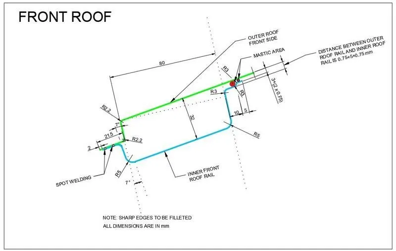
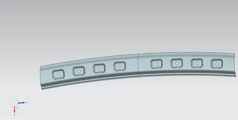
Front roof rail is the one which joins the wind shield glass, body side outer and the inner panel also. Here the front roof rail is designed based up on the master saection given.
REAR ROOF RAIL
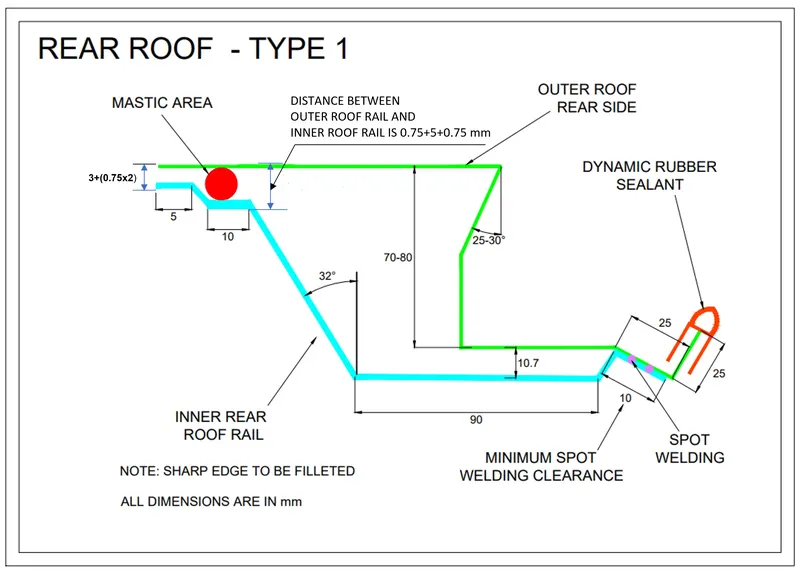
Rear roof rail is the one which joins the back door and the body side outer.
CENTRAL ROOF RAIL
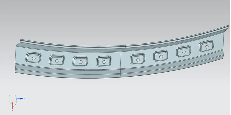
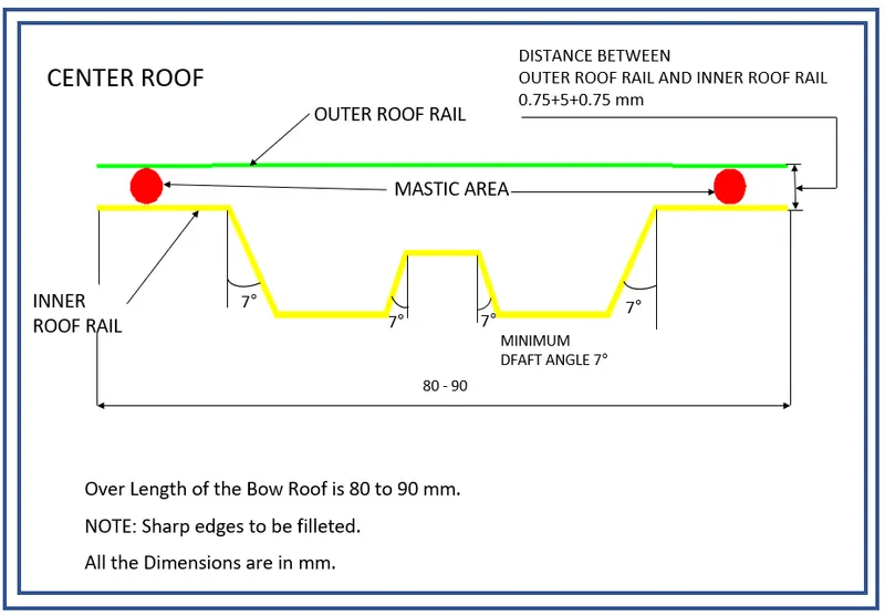
central roof rail helps in providing effectively support to the flat area of the roof as it is more susceptible to failure under the action of load. generally central roof rail is placed at the center of the roof which is connected to the B-pillar support structure. This central roof rail helps in adding the strength to the roof during the rool- over test. The thickness of the central roof rail is 1.25 mm.
BOW ROOFS
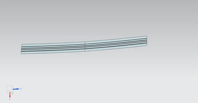
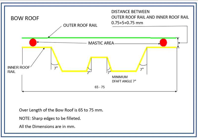
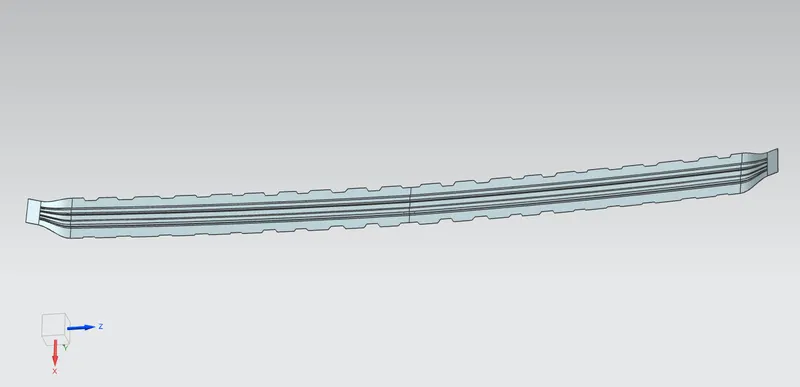
The bow roofs are give to improve the torsional stiffness and load bearing capacity of the roof structure. The number of bow roof present is depends on the overall size of the roof Presently in this project two bow roofs are added.
JOINING PROCESS
Mastics are introduced between the roof outer panel and the reinforcements for joining.where ever the mastic are introduced there is remarkable improve of the strength Spot welding is also introduced to join the reinforcements and the outer panel.
It is basically an NVH topic mastics are point/ surfaces given an embosses for applying mastic sealant to join outer and inner panel and also give good value of NVH.
So mastic sealants are joining material used to join inner and Outer panel and at the same time reduces the NVH value.
One spot of mastic sealant provides strength locally at around 80 mm so we need to put these mastic points in such a way that it covers the most of the hood region except reinforcement area of latch and hinge because that alone provide good NVH so no worries there.
CALCULATIONS
Heat Distortion Curvature Study
This study is used to find out and predict the heat distortion temperature at where the material starts to soften when exposed to a fixed load. So in order to avoid bending or damage of the roof based on this calculation we will decide the position on the roof bows on the roof.
W = [1.73 x 10^(-3) x L] + [1.85 x 10^(-8) x (R^2)/t] + [ 1.10x10^(-3) x l] - 2.68
Judgement Condition: OK< 2.7
Where,
L= Roof Length in X-Direction[mm](Roof dimension in 0-Y)
R=Roof curvature
R=2(Rx Ry)/(Rx+Ry)
Rx=X curvature
Ry=Y curvature
t-=Roof plate thickness [mm]
1=Bow Roof Span [mm]
| Position | Rx | Ry | R | I | L | t | W | OK/NG |
| FR AND 1ST BRR | 5776.4 | 2584.4 | 3571.07 | 399.9 | 2046.6 | 0.75 | 1.61 | OK |
| 1ST BRR TO CTR | 5006.6 | 6241.72 | 5556.9 | 4337 | 2046.6 | 0.75 | 2.09 | OK |
| CTR TO 2 ND BRR | 4013.3 | 10617 | 5824.7 | 434 | 2046.6 | 0.75 | 2.17 | OK |
| 2 BRR TO RRR | 3334.5 | 14516 | 5123.2 | 347.9 | 2046.6 | 0.75 | 1.89 | OK |
As per standards the value supposed to be lesser then the 3.1.In the Above Design, we have found the W value is lesser than 3.1 in all Components.Hence the Heat distortion criteria is satisfying.
Snow Load Criteria
This evalution is performed in cold regions where snow occurs.roof design must pass through these calculations to ensure that it has sufficent stiffness to withstand the load due to accomalation of snow over the roof.
Formula-
Qr = [Iy x t2] / [α x s x [(Rx + Ry)/2]2 x 10-8]
Note: The Qr value given over here is correct. There was a typo error in the formula given in the video.
Where
α = My x Lx2 x 10-12, My = Y(Ly - Y)
Judgement condition
Qr> 3.1
250 <= s <= 380
t=Roof plate thickness [mm]
Ly=Distance between the front and rear roof Rails on the Vehicle along with 0Y[mm]
Length of Roof panel with the center point between Roof rail Front/Rear as the reference point of the
front and the rear.
LX=Distance between the Left and Right end of the roof on the Roof BOW [mm]
Width of the roof panel exposed on the surface.
Y=Distance front Front Roof Rail to Roof BOW[mm]
s=Distance for which Roof BOW bears divided load [mm]
s = L1/2 + L2/2
ly=Geometrical moment of inertia of Roof BOW (Y cross-section )[mm-4]
Rx=Lateral direction curvature radius of roof panel Y cross-section on Roof BOW [mm]
Roof panel curvature Radius of the Length Ix in Front view
Ry= Longitudinal Direction curvature radius of the Roof panel X cross-section on Roof BOW [mm].
| Position | Iy | α | Lx | Ly | Y | s | Rx | Ry | t | Qr | Determination |
| FR AND 1ST BRR | 9.511 | 105.92 | 11898 | 2046.6 | 476.6 | 489.6 | 4556.4 | 2639.9 | 0.75 | 1.53 | NG |
| 1ST BRR TO CTR | 14.349 | 100.78 | 11396 | 2046.6 | 502.6 | 502.95 | 3791.5 | 6150.6 | 0.75 | 1.27 | NG |
| CTR TO 2 ND BRR | 9.93 | 96.09 | 11123 | 2046.6 | 503.3 | 492.5 | 4307.6 | 11110.8 | 0.75 | 3.39 | OK |
As per standards the Qr value supposed to be greater then the 3.1.In the Above Design,we have found the Qr value is greater than 3.1 is only in one Components.Other components need to strengthen with more embosses.hence the Snowload criteria is not satisfying.
SECTION INERTIA ANALYSIS
Section modulus is a geometric property for a given cross-section used in the design of beams or flexural members. Other geometric properties used in design includes area for tension and shear, radius of gyration for compression, and moment of inertia and polar moment of inertia for stiffness. Any relationship between these properties is highly dependent on the shape .
There are two types of section modulus
- The elastic section modulus
- The plastic section modulus
The elastic section modulus is defined as
where
S = I / y
S=Section modulus
I= second moment of inertia (or area moment of inertia, not to be confused with moment of inertia)
y=the distance from the neutral axis to any given fibre. It is often reported using y=c. where c is the distance from the neutral axis to the most extreme fibre
BOW ROOF RAIL 1
Create an intersection curve with the help of the plane and select the bow roof 1
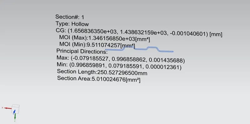
s=I/Y
Y=57.12 ,Y/2=28.56
S=9.511074257/28.56=0.333
Ceter roof rail
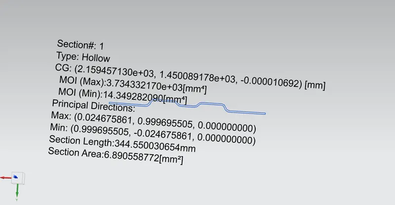
s=I/Y
Y=80.97,Y/2=40.48
s=14.349282090/40.485=0.354
BOW ROOF RAIL 2
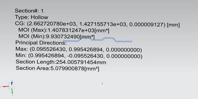
s=I/Y
Y=57.99,Y/2=28.99
s=9.930732490/28.99=0.342
Draft analysis
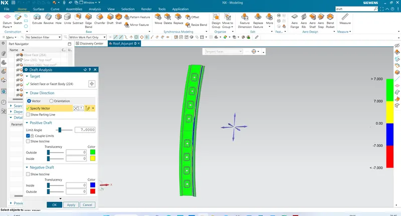
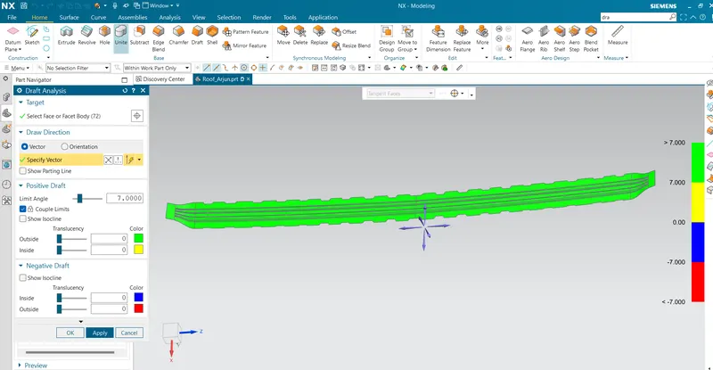
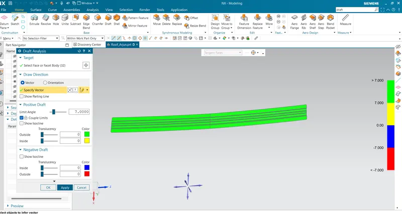
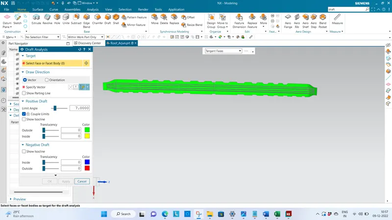
Parts Cannot be ejected from the tool if it is at 90 degree surfaces.For the reason A small Draft angle is to be provide for each and every surfaces of the Component in order to easy removal of component from the moulds without any defects. Draft is the angle in which the part is tapered to allow it to release Most of the sheet metal part require minimum 7degree to 10 degree.however 7 degrees are widely accepeted in sheet metal component design. Draft Analysis is the technique used to analyse weather our designed product are manufacturable with required conditions or not Below shown image is the Draft analysis of the above designed Roof.
Draft analysis of front roof rail
Draft analysis of bow roof rail
Draft analysis of center roof
Draft analysis of bow roof rail 2
Draft analysis of rear roof rail
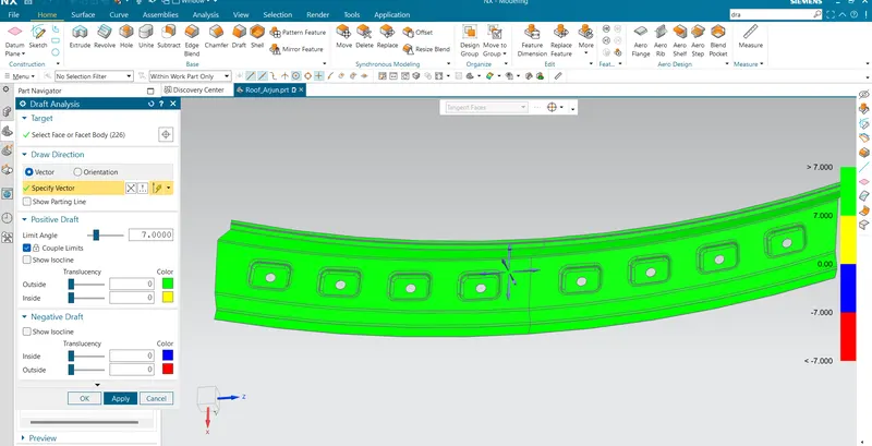
Draft analysis of top roof
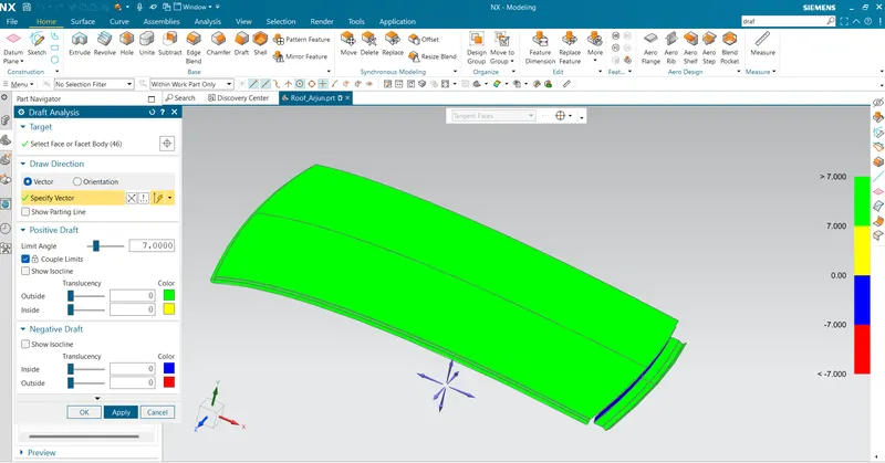
We gave a limit angle of 7 degree.
When the colour is green it means it has a positive draft it means area which are more than 7degree is shown as green. If it is shown in yellow that means it has less then 7 degrees and if in blue or red then it means it has negative draft.
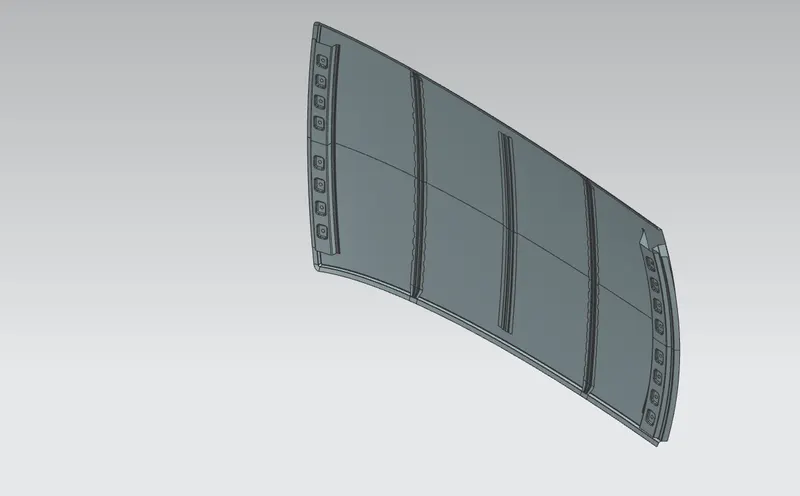
ISO METRIC VIEW OF ROOF
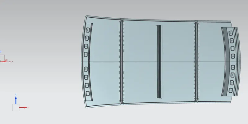
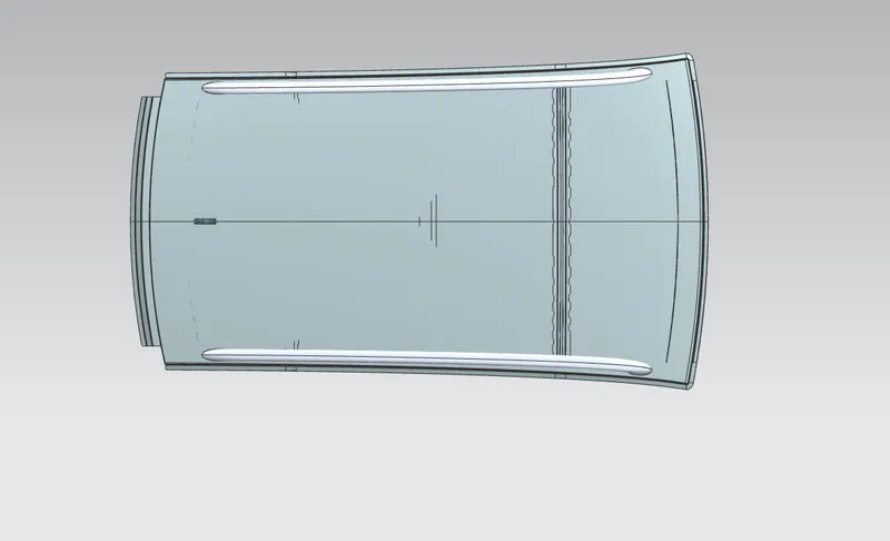
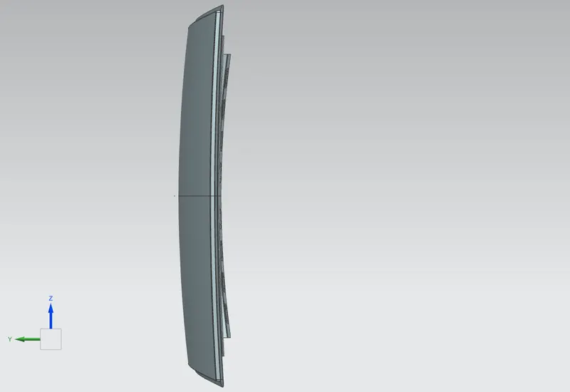
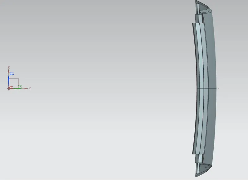
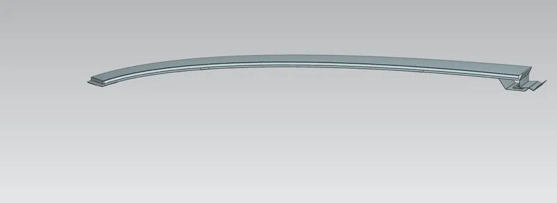
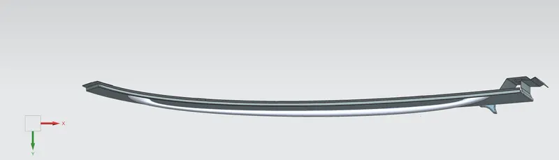
OTHER VIEWS
CONCLUSION
Hence the top roof, front roof rail, bow roof rails, central roof rail and the rear roof rail is designed by following the master sections and the moment of inertia, section modulus and draft analysis are carried out to check feasibility manufacturing.