Week 8 - Challenge 6 - Core & Cavity Design
OBJECTIVE:
- The objective of the project is to carry Draft Analysis by creating the tooling direction for the given Class-A surface.
- Create the class B and C surface for the Switch bezal with the given Class-A surface to design a component.
- Create core,cavity,parting line,parting surface for the switch bezal.
- INTRODUCTION:
- The Draft Analysis command enables you to detect if the part you drafted will be easily removed from the mould. This type of analysis is performed based on colour ranges identifying zones on the analyzed element where the deviation from the draft direction at any point, corresponds to specified values.
- Tooling direction is the main consideration for plastic part and mould parts because it defines the movement of the mould part and the possibility of the plastic part coming out from the mould part (Core and Cavity).
- The switch bezels are the plastic frames that cover the window switches and other controls found on the door of the car.and the switch bezel designed in this project having 2.5 mm thickness.
- Core and cavity is designing for manufacturing of switch bezal.
PROCEDURE
- Open the given CATPART and check for the gaps and boundaries of the component by using boundary option and selecting the whole component. any unwanted gaps in the model will be highlighted easily.
- The tooling axis needs to be created (the direction of the Mold input), perform all the operation in the separate geometrical set an name it accordingly.
- Firstly, create a point in the desired location and between the hole in the component.
- Create a Dummy Tooling Axis with the center point in Z direction.
- Now using the intersection option select the component and the YZ-Plane to create a intersecting lines on the component. Make sure to keep all sub elements.
- Now with the reference on the intersecting lines create another lines using point-point option and extend them accordingly.
- Now create a bisecting- line with reference of the two newly created lines and point
- Bisecting line were used to get the exact medium so that maximum positive draft angle can be achieved.
- Finally by using the bisecting line option the tooling axis were created.
Publication:
- The tooling axis and class-A surface were published for further easy reference.
- What is Draft?
- Draft is providing angles or tapers on product features such as walls, ribs and bosses that lie parallel to the direction of release from the mold eases part ejection.
- Draft allows for the parts to release from the mold.
- Draft is required on all parts in the direction of mold movement in order to allow parts to release or eject form mold properly.
- Draft is the angle in which the parts is tapered to allow it to release. As the part cools, it tends to want to shrink to the core side of the mold.
- Adding draft helps the part to release. Most parts or applications require minimum of 1/2 to 1 degree, however 3 degrees is widely accepted as the norm.
DRAFT ANALYSIS:
- For plastic parts, the nominal angle value for draft analysis is 3 degree but even a 0.5-degree angle can be created for sub-assemblies like ribs and slots. (For Sheet Metal 7 degree angle is the nominal value)
- Insert - Analysis - Feature Draft Analysis.
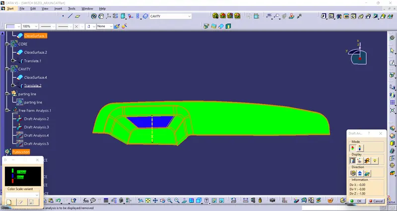
- Draft analysis was carried out by pulling the compass to the tooling axis and an inverse draft axis was carried out if required.
- After setting the compass over the tooling axis the compass must be locked to a specific direction.
- If the surface was in green then the model passes or else further operations need to be carried out.
DRAFT ANALYSIS ON CLASS A SURFACE
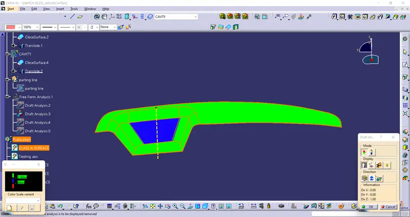
FINAL DRAFT ANALYSIS
Class A Surface :
In automotive design application Class A Surfaces are created on all visible exterior surfaces (ex; body panels, bumper, grill, lights etc.) and all visible surfaces of see-touch & feel parts in interior (ex: Dashboard, seats, door pads etc.). This can also include beauty covers in the engine compartment, mud flaps, trunk panels and carpeting. This surface has 0 mm thickness.The given CLASS A SURFACE should be in IGES OR STEP format.
When opening the file of class a surface, it will be combination many surfaces.After that it should be join in the tolerance of 0.001(Maximum value is 0.1).And publish the joined surfaces as class A surface.
Class-B Surface
This surface is created by taking direct offset from class A surface. It is the surface on which all engineering feature like screw bosses, dog house, ribs & mounting are created.
when offseting the class A surface many erronimous sufaces may appear.The erronimus surfaces can remove and repair by the help of tools like Multi section suface,fill,blend and sub element to remove etc.The class b surface should not contain any kinds of gap .By using boundary comand we can check the gap in surfaces.
Class-C Surface
This is the surface that joins class A & class B together.The c suface mainly done though sweep tool.the sweep suface created either with the referance of tooling axis or with referance to the surfaces.the draft angle of the sweep surface which are perpendicular to the tooling axis is given as 87 degree.And parallel to the tooling axis will be 3 degree.
After creating class c surfaces this steps will follows:
- Joining the Class A & C Surface.
- Trimming the Class B & C surfaces and get the final trimmed switch bezal closed surface.
- Solid Model is created in part workbench by using Close Surface command.
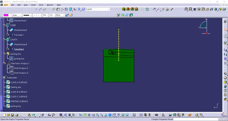
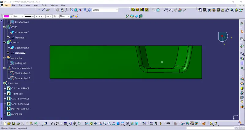
CAVITY
It forms the external Shape of the moulding. Generally, the cavity is situated in the Fixed half. The plate in which the cavity is formed is known as the cavity plate.
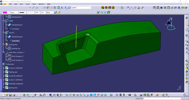
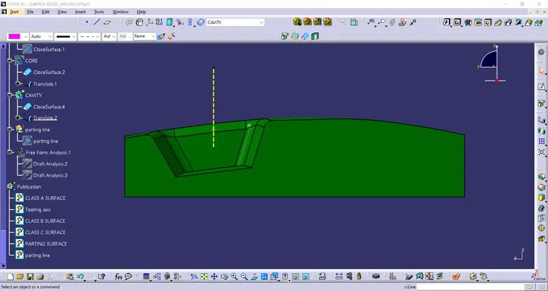
CORE
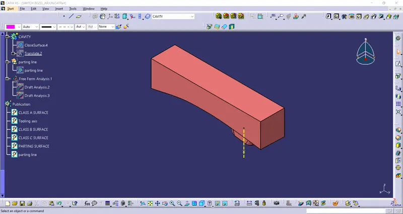
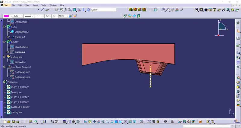
It forms the internal shape of the moulding. Generally, the core is situated in the moving half. This is because, it is easier to provide the ejector system in the moving half. The core assembly is divided in to two portions
Core plate-the plate from which a core projects is termed the core plate.
Core insert-It is the actual profile of core. The core includes many combinations of core insert.If any modifications or repair is needed we can take out the core insert seperatly.It avoiding effort of removing whole assembly.
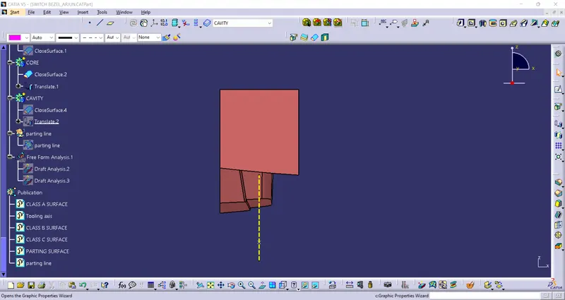
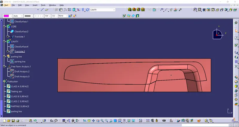
Injection mold parting surface.
Generally, injection mold has two major components: the movable halve and the fixed halve, during injection molding process, these two halves are pressed tightly and form a sealed hollow to avoid the melt flow leakage and maintain certain holding pressure, the pressed surface are called parting surface, usually parting surface are the biggest projection outline of the part.
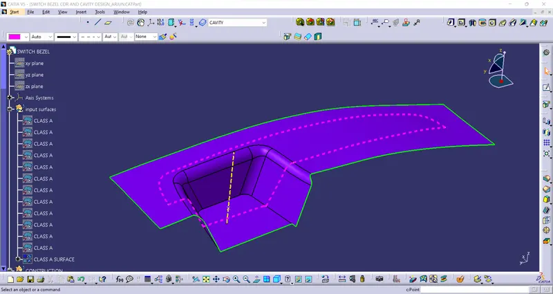
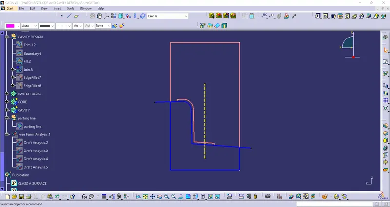
Parting surface design principles
Parting surface design directly affects the product quality, ease of construction and operation of the injection mold, the mold design is one of the key factors to success.
Design parting surface should follow the following principles:
1. Design the injection mold structure as simple as possible. Avoid or reduce side parting as much as possible to reduce the complexity of mold making
2. Ease of de-molding. As far as possible, for instance, the plastic parts should stay in fixed halve of the injection mold and ejected by ejection system, avoid side de-molding action.
3. Ensure the dimensional accuracy of the molded parts. Try to make the parts with similar dimensional accuracy requirements in the same module to reduce manufacturing and assembly errors.
4. Ensure appearance requirement of the molded parts. Flash or mismatch occurs usually on parting surface, so the parting surface should not be designed on any high quality requirement surfaces.
5. Ensure adequate venting If possible, parting surface should be place at the end of the mold flow. This is going to be a good advantage of filling and venting.
PROCEDURE FOR CREATING CORE.
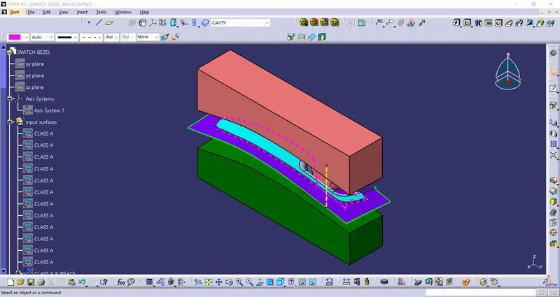
- Create boundary on class A surface and extapolate upto 15mm.
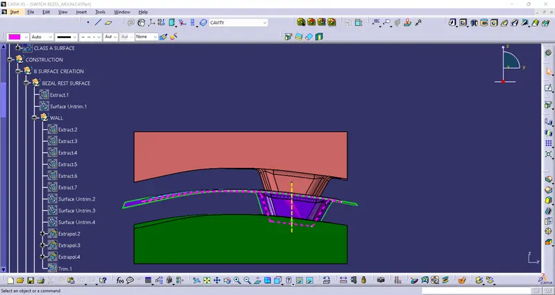
- Trim extrapolated surface with c surface.
- For creating parting surface trim b surface with previously trimmed surfaces.
- Create extrude of rectangle from the parting surface in tooling direction and trim with parting surface.
- use fill option to cover the top
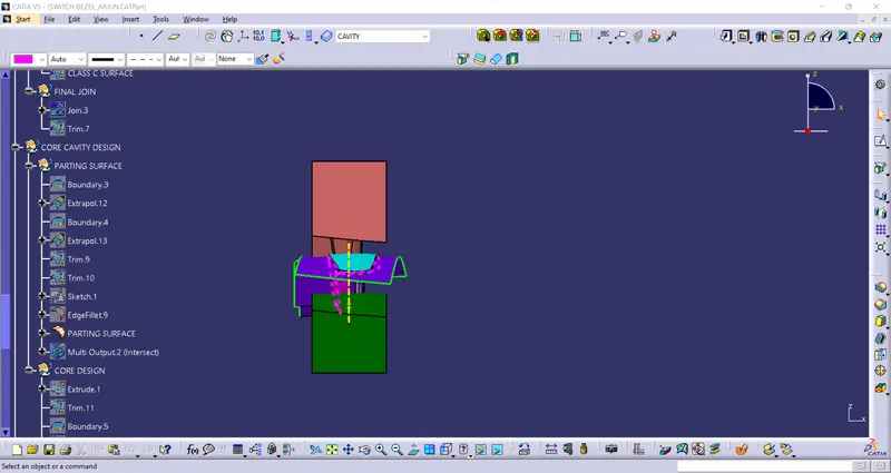
- Join all the surfaces with 0.001 mm tolarance.
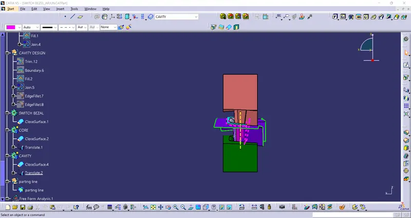
- Use close command to close the core body.
Procedure for creating cavity.
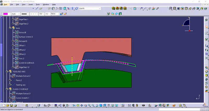
- Trim the extruded surface with b surface.
- Fill the bottom by using fill command.
- join all the surfaces with 0.001 mm tolarance.
- Use close command to close the body of cavity.
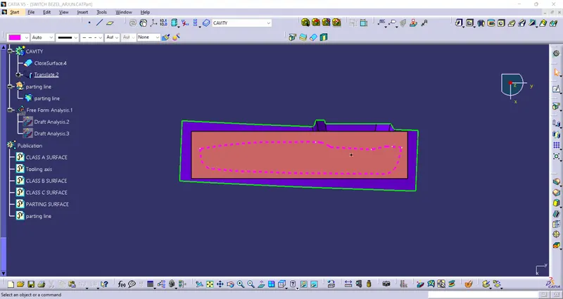
- intersect switch bezal,core,cavity and parting surface to create parting line.
Conclusion
Created core and cavity of switch bezal with given procedure.