Radar Mast & Final Assembly of Yacht
DESIGN AND ASSEMBLY OF SUNSEEKER PREDATOR YACHT USING SOLIDWORKS
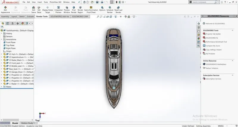
Objective:-To design individual components of Sunseeker Predator Yacht using solid works and assemble them in a felicitous way and render it to make a realistic view of the model using photo view and solidworks visualize. The whole process is carried out in Solidworks tool.
Introduction: - This project is accomplished using Solidworks by sketching and part modelling each component and then they were sent to the assembly process to assemble each part in arrangement to demonstrate a Sunseeker Predator Yacht. This report explanation includes basic commands used while designing the model step by step.
Components of Sunseeker Predator Yacht
- Propeller
- Radar
- Hull
- Garage Door
- Front Seat
- Middle Seat
- Rear Seat
- Super Structure
- Radar Mast
Design methodology
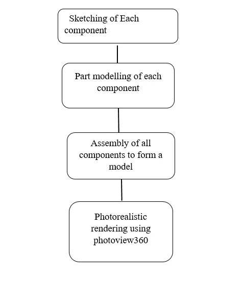
Sketching: - A rough diagram that represents the chief features of an object, to examine the model before going into part modeling.
Part modeling: - It is the next process of sketching where we will be giving a calculated dimension of the virtue prototype of an object by modeling each individual part separately.
Assembly: - In this, we will insert each component and assemble them using mates to form a model.
Tools used in surface modeling in designing sunseeker predator yacht
- Extrude Surface:- You can create extruded surfaces from models that include 2D or 3D faces and knit the extruded surfaces to surrounding features.
- Extended Surface:- You can extend a surface by selecting an edge, multiple edges, or a face. Under Edges/Faces to Extend, select one or more edges or faces in the graphics area for Selected Face/Edges. For edges, the surface extends along the plane of the edge.
- Swept surface:-
Create planes for sketching the sweep profile, sweep path, and if necessary, the guide curves. If you are using guide curves, create coincident or pierce relations between the guide curves and the profile.
- lofted surface:- loft Surfaces are surfaces generated by multiple 3D Curves or existing edges creating a smooth tangency between the selected curves. Match Points are created between each selection denoting the orientation and path of the loft surface.
- Boundary surface:- The boundary surface feature lets you create surfaces that can be tangent or curvature continuous in both directions (all sides of the surface). In most cases, this delivers a higher quality result than the loft tool.
- Ruled surface:- The Ruled Surface command creates surfaces that extend out in a specified direction from selected edges.
- Filled Surface: The Filled Surface feature constructs a surface patch with any number of sides, within a boundary defined by existing model edges, sketches, or curves, including composite curves.
- Knit surface: Use the Knit Surface tool to combine two or more faces and surfaces into one. Create a solid body when the knit surfaces form a closed volume or leave as a surface body.
9.Delete surface: To delete the face on the plane or bodies
Tools used in solid modeling in designing Sunseeker predator yacht:
- Extrude boss/base:-An Extruded Boss/Base feature will allow you to take a 2D sketch and add thickness to it in the third dimension. Every few releases, this feature gets some terrific functionality added to it.
- Extrude cut: Extruded cut feature removes material from the part. The End Condition, Draft, and Thin Feature options are the same as described in Extruded Boss/Base.
To create an extruded cut:
1) Sketch the profile for the cut.
2) Click Extruded cut on the Features toolbar.
- Fillet: - Fillet/Round creates a rounded internal or external face on the part. You can fillet all edges of a face, selected sets of faces, selected edges, or edge loops.
- Chamfer:-
The chamfer tool creates a beveled feature on selected edges, faces, or vertex. Set the Distance and Angle in the Chamfer Property Manager or in the graphics area. A manipulator arrow appears that points in the direction in which the distance is measured
- Offset:-.
Offset one or more sketch entities, selected model edges, or model faces by a specified distance. For example, you can offset sketch entities such as splines or arcs, sets of model edges, loops, and so on. You can also offset finite lines
- Convert entities: - The Convert Entities tool allows users to make a copied projection of a given sketch, face, or set of edges onto the active sketch plane. These sketch entities will update their size and/or positioning if either of these characteristics changes in the source sketch.
- Dome:-The software calculates the distance using the radius of the arc as a basis for the dome. It creates a dome that is tangent to the adjacent cylindrical or conical face.
- 7. Spline: - A Spline sketch is defined by its continuously changing curvature. Points are placed to shape the curve.
- Trim entities: - Select the trim type based on the entities you want to trim or extend. All trim types are available with 2D sketches and 2D sketches on 3D planes. You can use any of the following trim options: Power trim.
- Revolve base: - Revolved Boss or Base is a SolidWorks feature tool that is used to create a solid 3D model around an axis.
Description of Surface modeling and Solid modeling of components in Sunseeker predator yacht
- Propeller
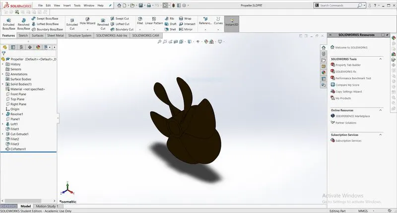
Tools used in solid modeling in designing Propeller:
- Revolve
- Loft
- Fillet
- Extrude cut
- Circular pattern
- Radar
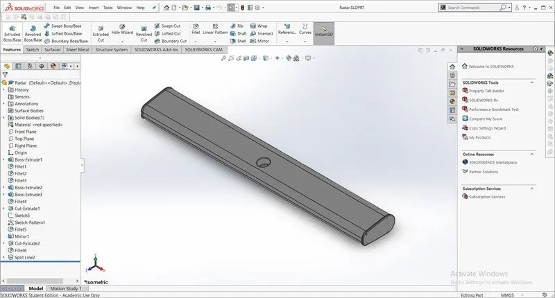
Tools used in designing radar :
- Boss Extrude
- Cut extrude
- Fillets
- Sketch pattern
- Mirror
- split line
3.Hull
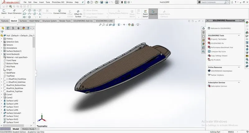
Tools used in surface modeling in designing Hull:
- Extend surface
- Extrude surface
- Surface offset
- Lofted surface
- Ruled surface
- Projected curve
- Surface trim
- Surface knit
Tools used in solid modeling in designing Hull:
- extrude boss/base
- Extrude cut
- Fillet
- Chamfer
- Sweep
- Mirror
- Split lines
- Delete faces
- Linear pattern
- Shell
- Garage Door
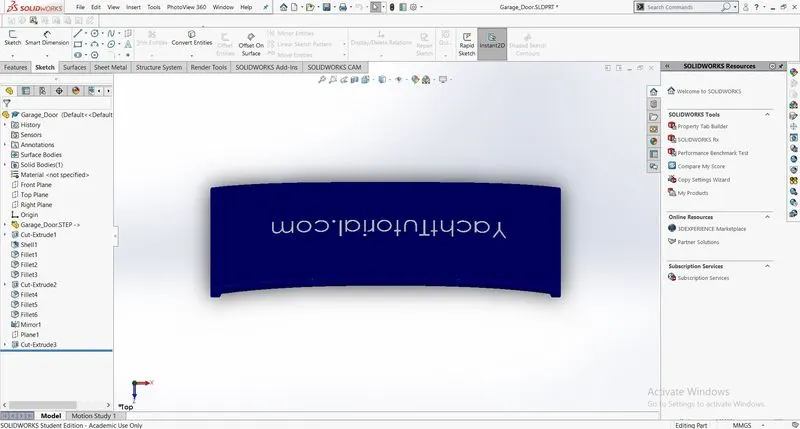
Tools used in solid modeling in designing Garage door:
- Cut extrude
- Shell
- Fillet
- Mirror
- Front Seat
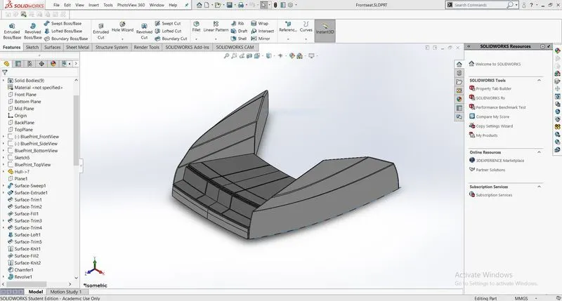
Tools used in surface modeling in designing Front Seat:
- Surface sweep
- Surface extrude
- Surface trim
- Surface fill
Tools used in solid modeling in designing Front Seat:
- Revolve
- Boss extrude
- Cut extrude
- Chamfer
- Fillet
- Dome
- Mirror
- Middle Seat
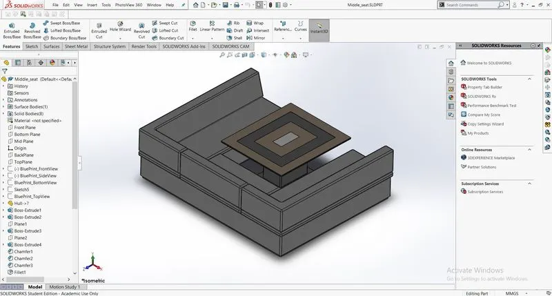
Tools used in solid modeling in designing Middle Seat:
- Boss extrude
- Chamfer
- Fillet
- Mirror
- Rear Seat
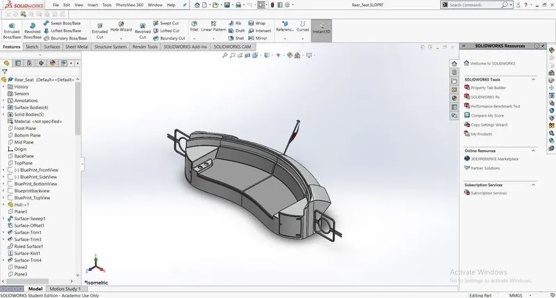
Tools used in surface modeling in designing Rear Seat:
- Surface Sweep
- Surface extrude
- Surface trim
- Surface knit
- Surface loft
- Surface extrude
Tools used in solid modeling in designing Rear Seat:
- Surface offset
- Boss extrude
- Cut extrude
- Chamfer
- Fillet
- Sweep
- Mirror
- Super Structure
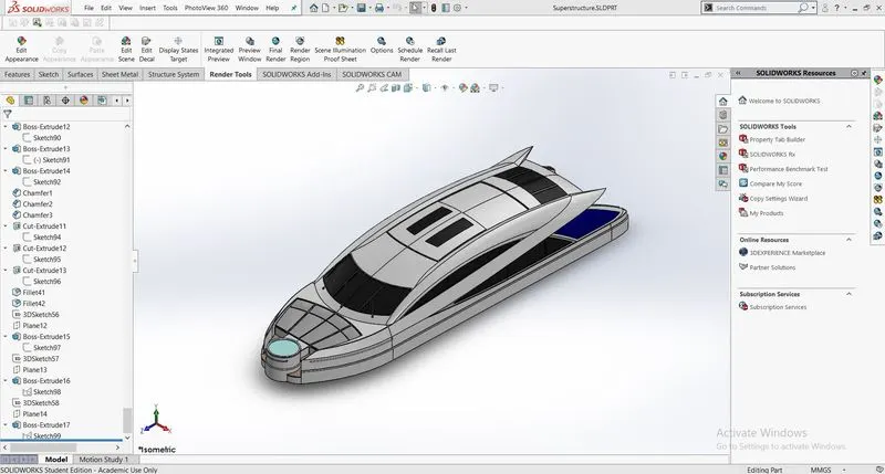
Tools used in surface modeling in designing Superstructure:
- Surface extrude
- Ruled surface
- Lofted Surface
- Surface sweep
- Surface trim
- Surface knit
- Extended surface
- Projected curve
Tools used in solid modeling in designing Superstructure :
- Boss extrude
- Cut extrude
- Chamfer
- Delete faces
- Surface offset
- Thickness
- Dome
- Sweep
- Mirror
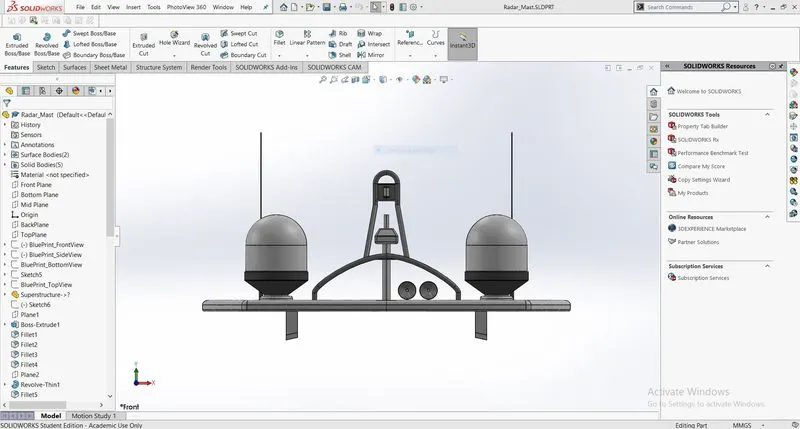
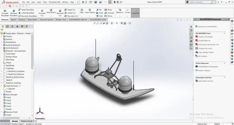
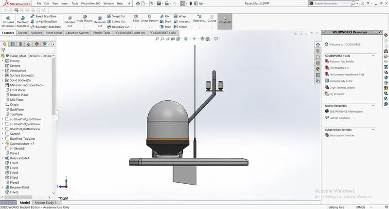
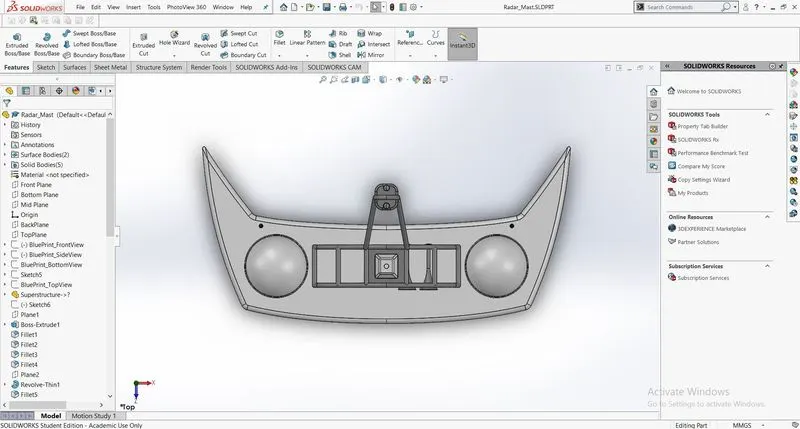
- Radar Mast
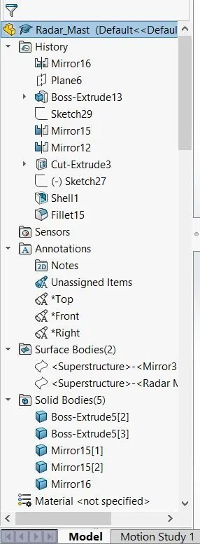
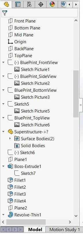
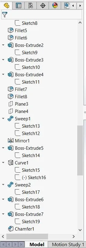
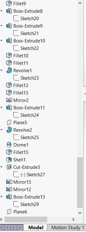
Tools used in solid modeling in designing Radar mast:
- Boss extrude
- Revolve
- Fillet
- Cut extrude
- Sweep
- Curve
- Shell
- Mirror
- Combine
Assembly of the Sunseeker Predator Yacht:
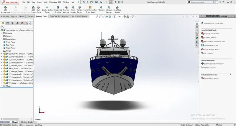
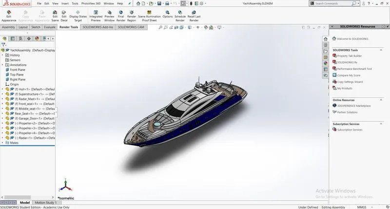
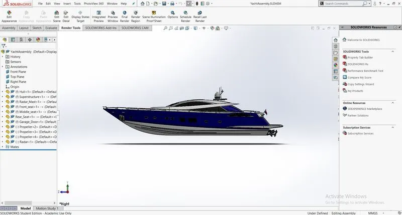
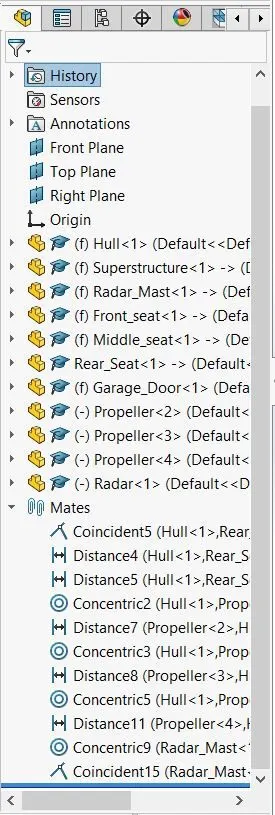
- Initially the Hull part is inserted in the assembly by using insert parts in the option. After that the part is inserted in the assembly environment and click ok to fix the Hull.
- After that other parts of the Sunseeker Predator Yacht are inserted into the assembly and given passible mate conditions.
Front View
Top View
Side View
Isometric View
Features used to Sunseeker Predator Yacht:
- Inserting Parts
- Mates
Mates:
Mates create a geometric relationship between the assembly components. As we add mates, we define the allowable directions of linear or rotational motion of the components. We can move a component within its degree of freedom, visualizing the assembly behavior.
Rendering:
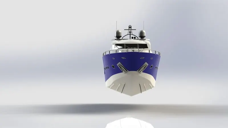
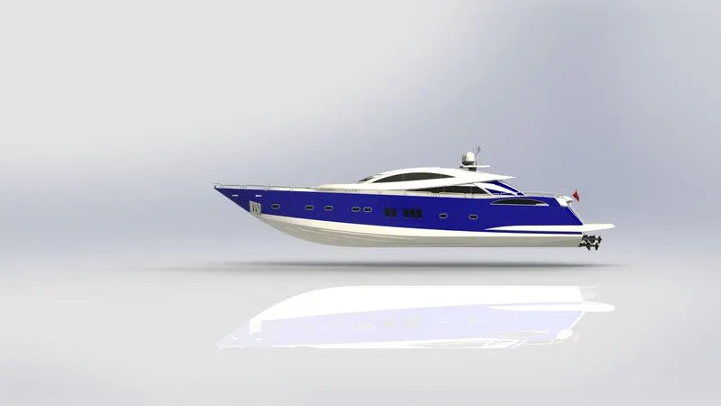
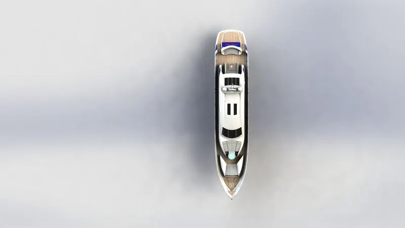
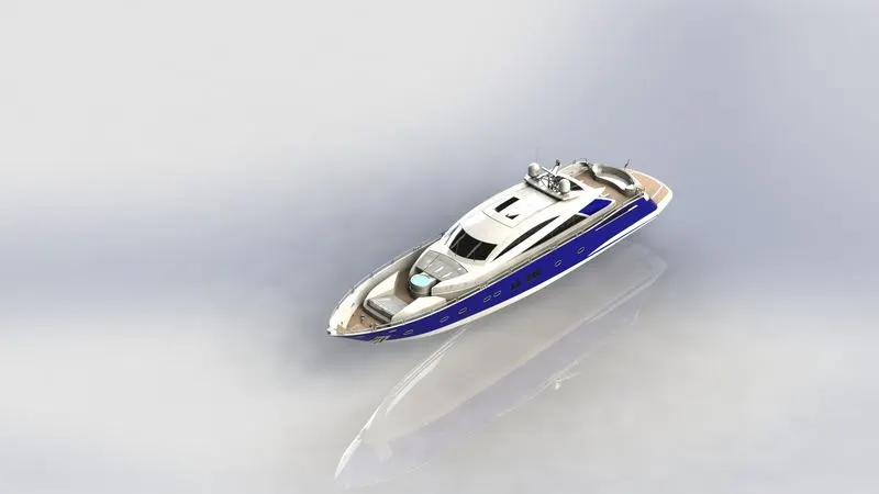
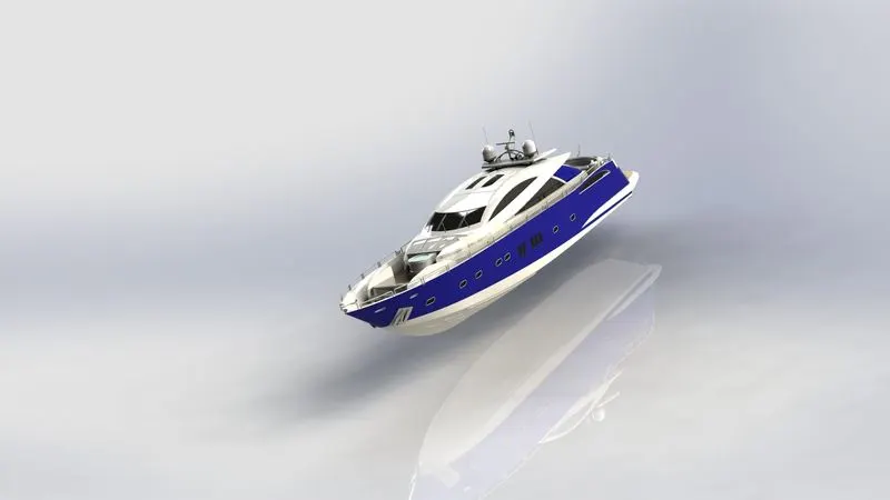
- Rendering is a process of creating realistic images of the photorealistic model with the environment.
- Rendering has been done in two ways in Solidworks:
- Photo view 360
Rendered Images
Conclusion:-
We have designed Sunseeker Predator Yacht using Solidworks and rendered it using photo view 360 and by designing this model I have learned some advanced commands in Surface modeling and Solid Modelling in Solidworks