Project - Speed Control of a Direct Current (DC) motor
Aim:
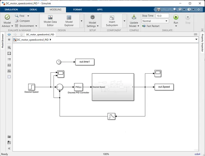
In this project, a Simulink model for the DC motor will be first developed per the schematic shown in Figure 1.
Use the Proportional, Integral, and Derivative (PID) control design knowledge gained in the training to design, develop and test a controller to maintain a desired speed for the motor.
Ans:
Subsystem Dc motor is connected to the discrete PID controller to maintain the desired speed as it is.
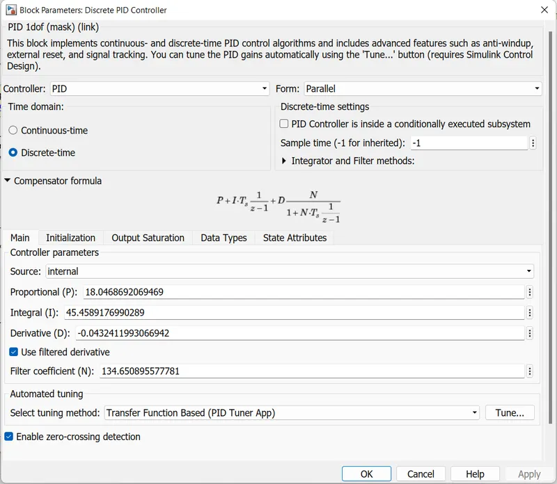
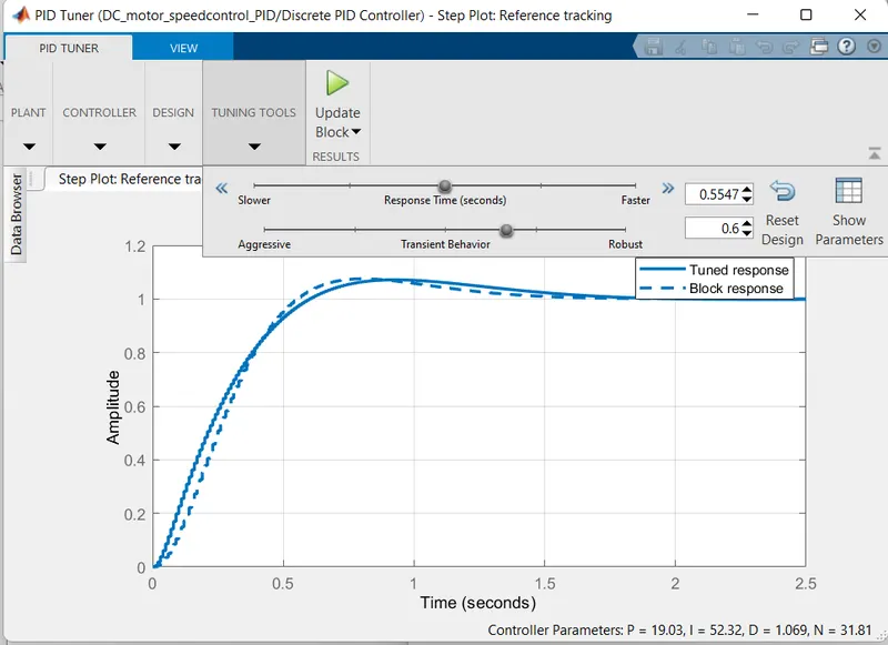
After that Pid controller begin with Kp,Ki,Kd as 1.0,1.0,0 after tuning accordingly, we can adjust Kp,Ki,Kd as
18.04, 45.45, -0.04 respectively. To obtain Control Design Objectives.
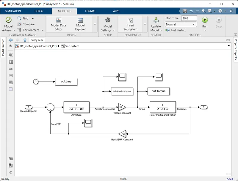
Subsystem of DC motor:
Discrete PID controller block parameter:
.m file for defining DC motor parameters:
% Design parameters of motor
J = 0.01;    % Moment of inertia of the rotor in kg-m^2
B = 0.1;     % Motor viscous friction constant in N-m-s
Km = 0.01;   % Back emf constant in v/rad/s
Kt = 0.01;   % Motor torque constant in N-m/amp
Ra = 1.0;    % Resistance of armature circuit in ohms
La = 0.5;    % Inductance of the armature circuit in henries
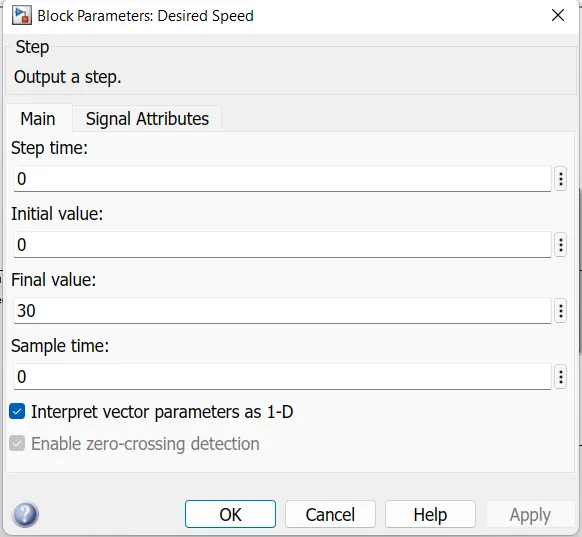
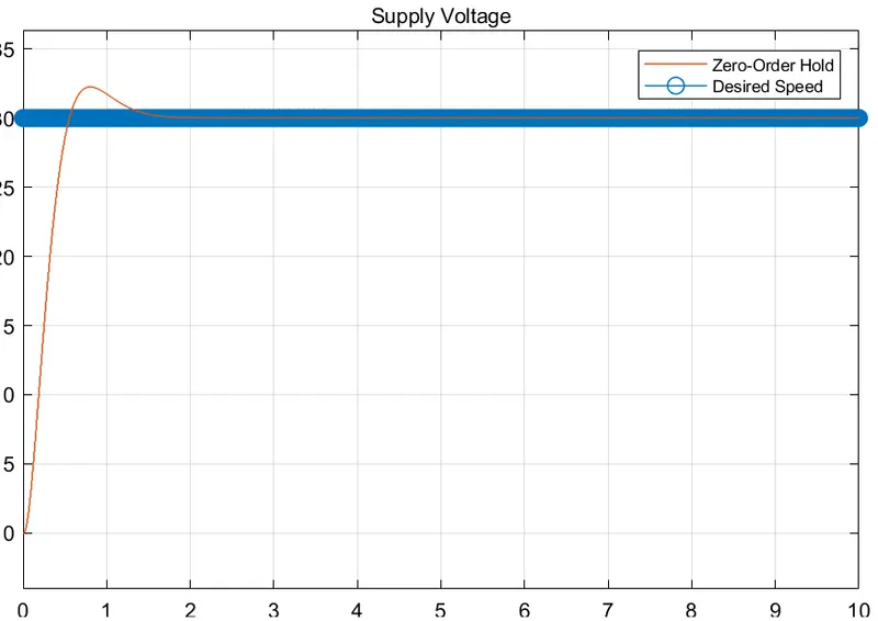
Taking step block as input the desired speed is 30:
Tunning plot:
Graph of desired speed and actual speed w.r.t time:
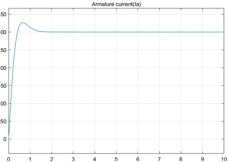
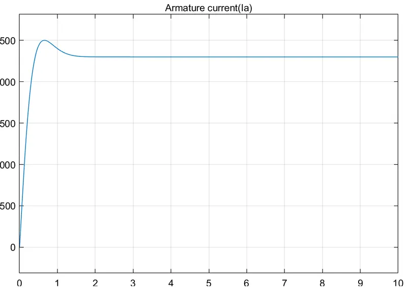
Armature current(Ia):
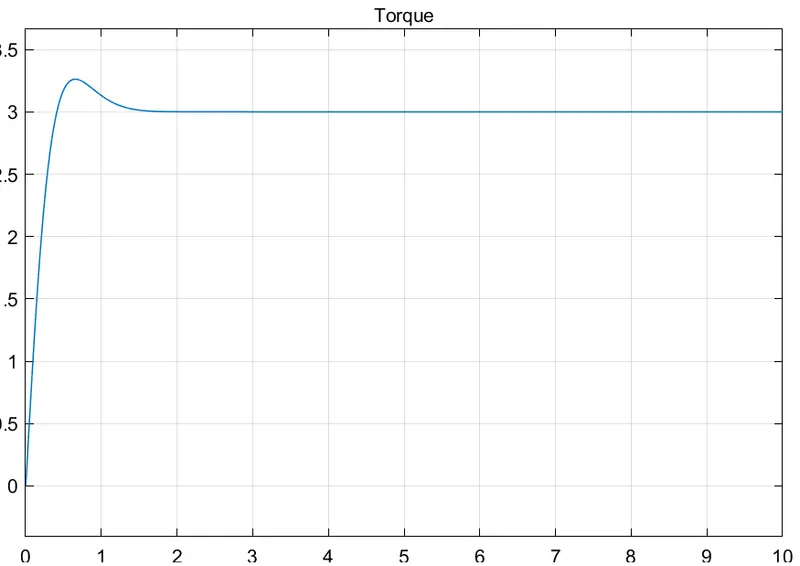
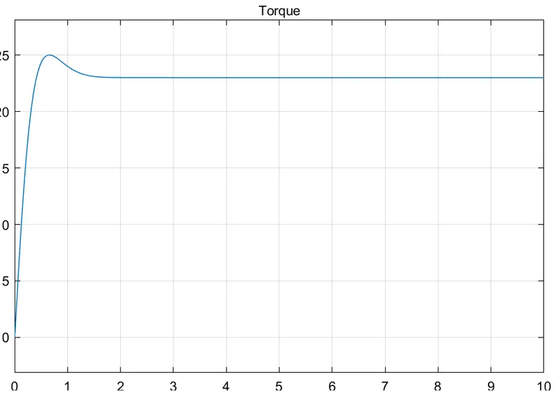
Torque:
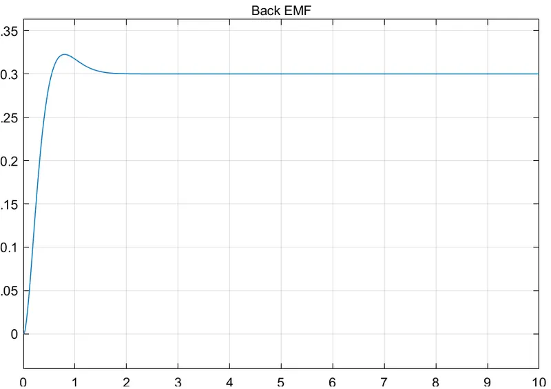
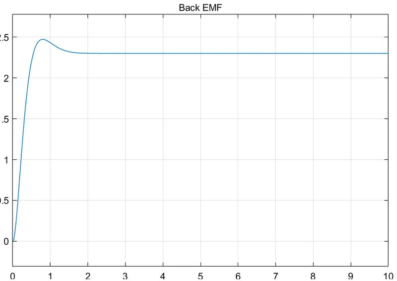
Back EMF:
Speed:
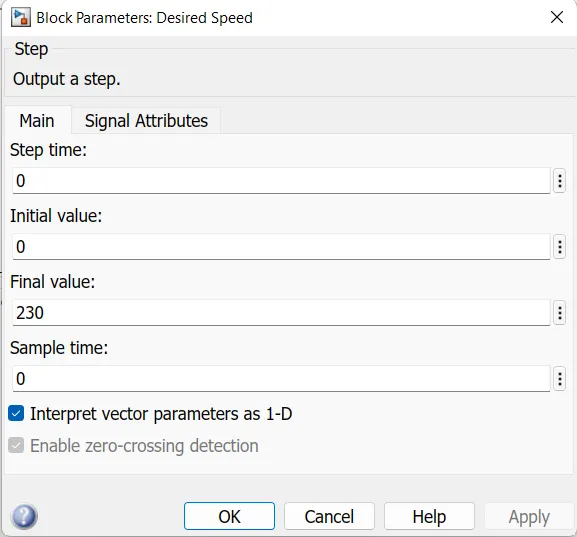
At the desired speed of 230:
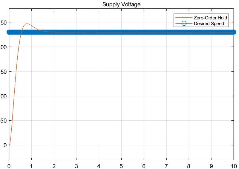
Desired and actual speed w.r.t :
Armature current:
Torque:
Back EMF:
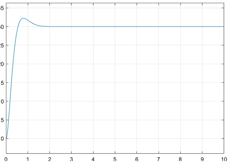
Speed:
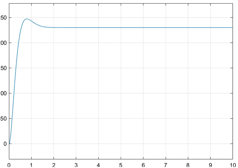
In above two cases,we change desired speed as 30 in case 1 and 230 in case 2 , since the both a case, Plotting Remains same. Hence, we maintain desired Speed For a Dc Motor.