Project - Position control of mass spring damper system
Obtain the transfer function of a mass spring damper system and use it in the model. Add a PID controller to adjust the force on mass so that its position follows a reference signal.
Take m = 3.6; %kg k = 400; %N/m c = 100; %Ns/m
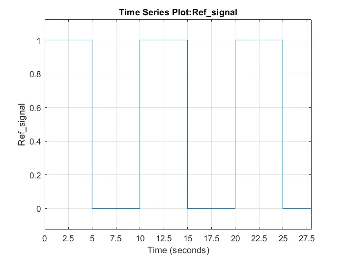
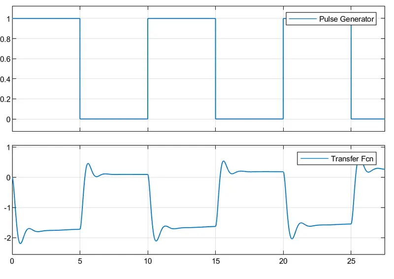
The reference signal is shown in the following figure.
Answer:
The spring-mass-damper system consists of a mass with weight (m), a spring with stiffness (k), and a shock absorber with a damping coefficient of (c). This system works based on Newton’s second law, which states that Force is equal to the rate of change of momentum. For a constant mass, force equals mass times acceleration.
Given values;
m = 3.6 kg; k = 400 N/m; c = 100Ns/m
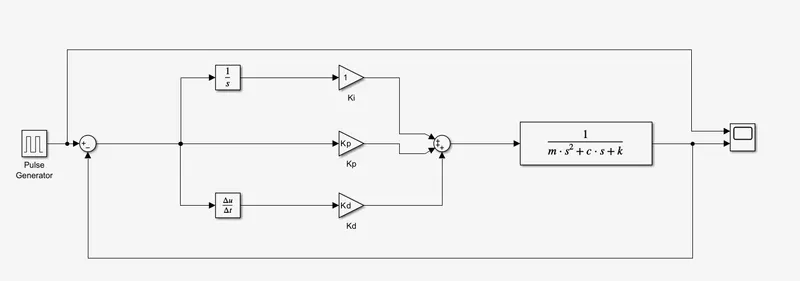
Simulink Model of mass spring damper system without PID controller block:
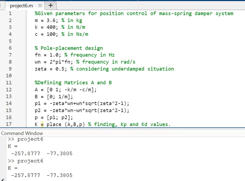
Pole placement in MATLAB code:
In this model we have used the following blocks:
Pulse generator:
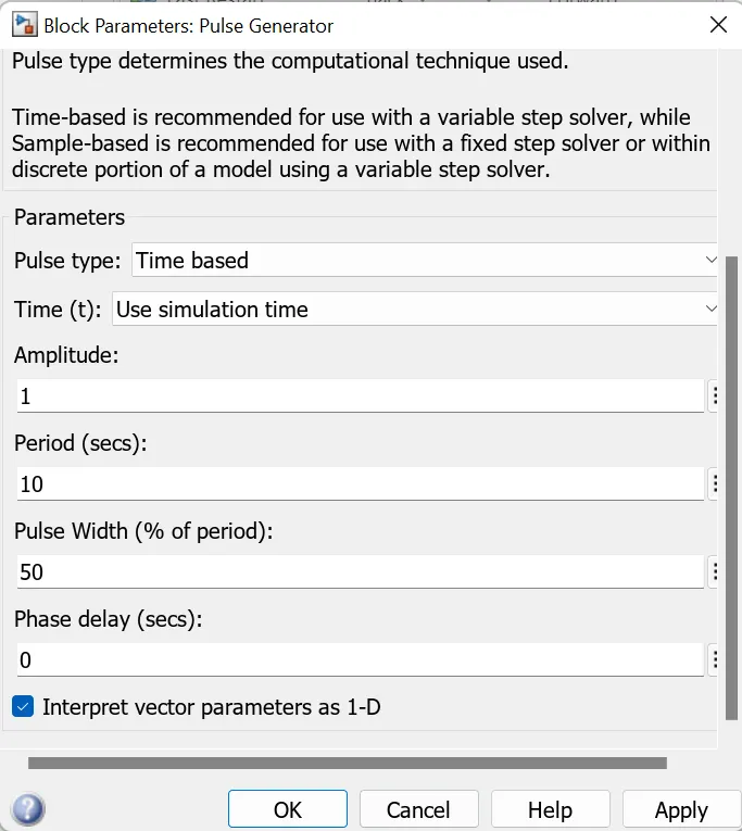
Here we have used the pulse generator to create the givem reference signal.
Integrator block:
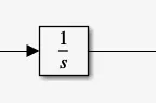
For Continuous-time integration of the input signal.
Derivative block:
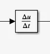
Gives numerical derivative: Δu/Δt.
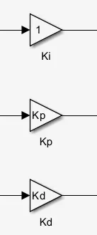
Gain blocks for Kp, Ki and Kd:
Transfer function block:
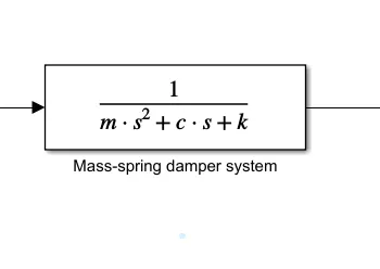
Results:
1. When Ki = 1;
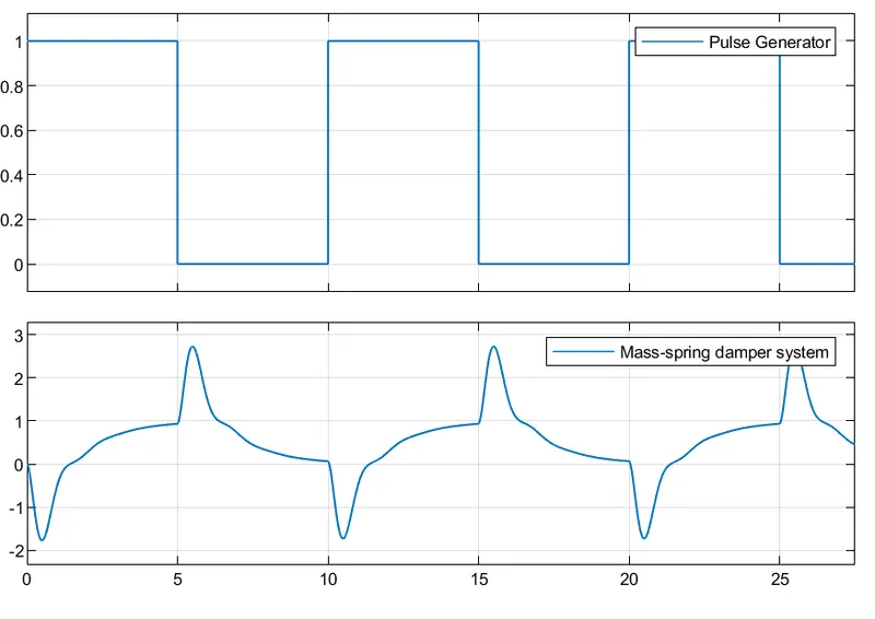
2. When Ki = 100;
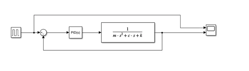
Simulink Model of mass spring damper system with PID controller block:
The given parameters are defined in MATLAB code:

The blocks used here are;
Pulse generator:
Here we have used the pulse generator to create the givem reference signal.
PID controller:
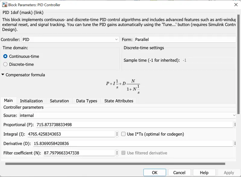
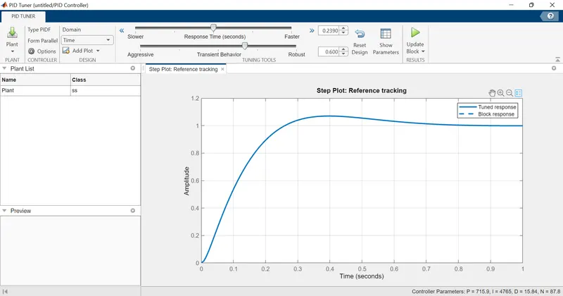
We have tuned the PID controller, to get the exact values of the Kp, Ki and Kd. After tuning we received the below response.
Results:
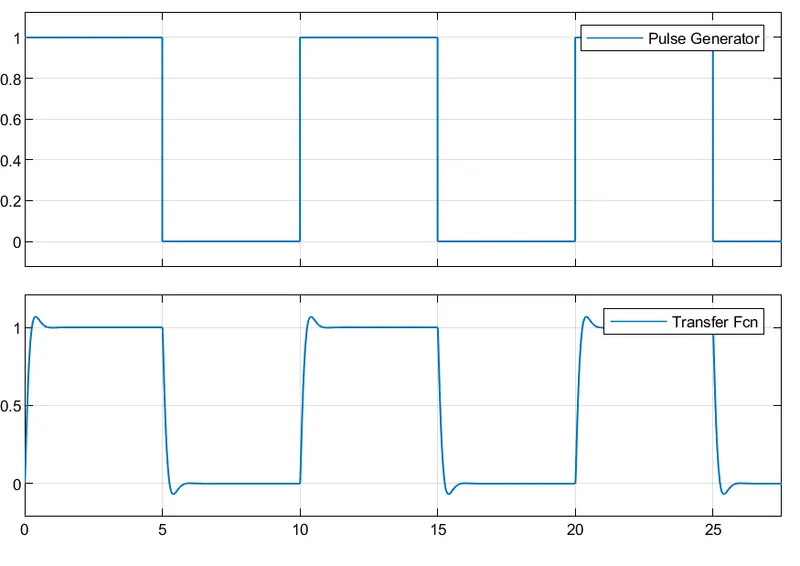
The results shows that the system is following the given input reference signal perfectly, when the PID controller is used after tuning to correct values of Kp, Ki and Kd.