Project - 2 - Meshing on the suspension Assembly
AIM: To create mesh for suspension assembly as per methodology, Quality parameters and to connect all the parts for further processing.
METHODOLOGY USED:
Step 1: Geometry clean-up and topology.
Step 2: Shell meshing
Step 3: Volume meshing
Step 4: Setting up connections
Steps are discussed in details below.
STEP 1: Geometry clean-up and topology.
Major steps include checking for errors << Auto-fix errors << Creating new faces as per requirement
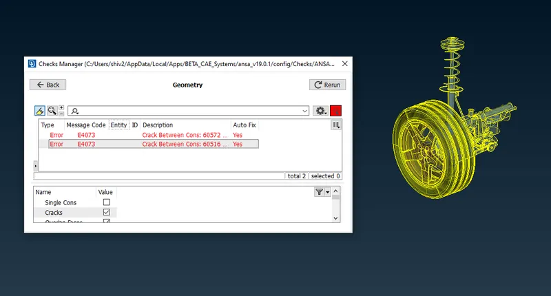
Fig: Geometry is checked for errors like unchecked faces, cracks etc.
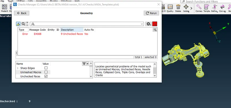
Fig: Unchecked faces are obtained after applying Auto-fix.
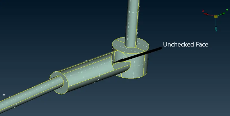
Fig: Unchecked faces
Note: Corrective methods like creating cuts and making new coons faces is used to check the face without tempering the shape of the parent body.
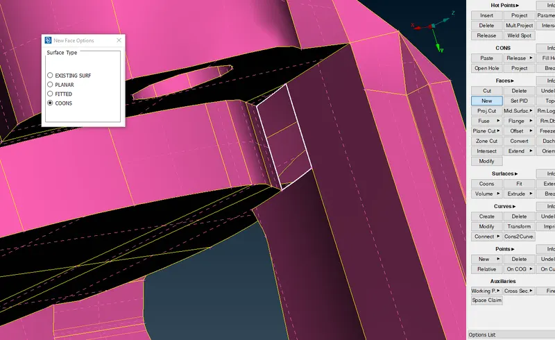
Fig: New coons face is generated.
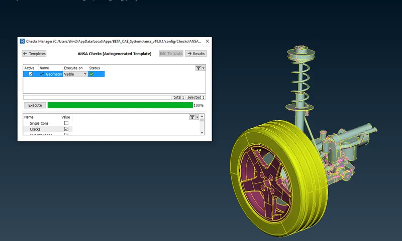
Fig: Geometry passes all the quality check parameters.
Now, as per our methodology mesh process is initiated.
STEP 2: Shell Meshing
The process line is discussed below.
Note: Parts with uniform thickness less than 4 MM are considered for the mid-surface generation where PSHELL property is assigned a thickness of the parent body.
Input Mesh parameters, shell quality, and solid quality parameters as per given data >> Meshing >> Off elements correction
For non-uniform parts, volume meshing with TET-Collapse value will be considered as a quality parameter.
shell meshing is done first in the process later volume will be defined and volume mesh is generated in the format of PSOLID cards.
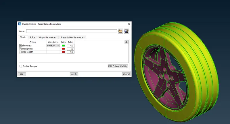
Fig: Quality parameters are input.
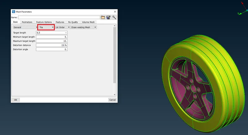
Fig: Tria elements are used for meshing.
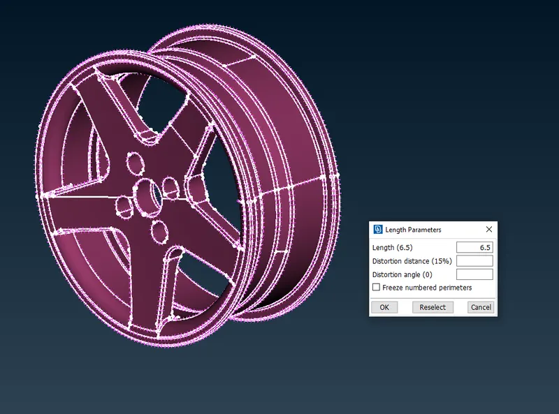
Fig: Parameter and macro length is set.
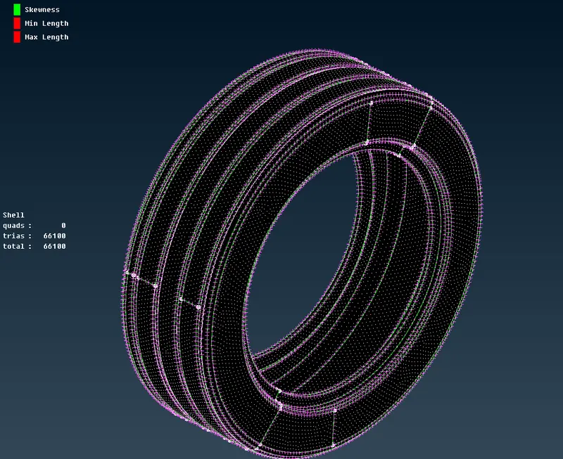
Fig: Tria meshing is done.
Note: Similar meshing is done for RIM too.
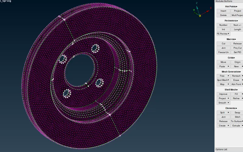
Fig: RIM meshing
Now similar process is done for non-uniform parts.
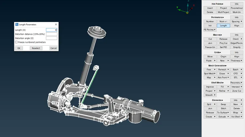
Fig: Length parameters are set.
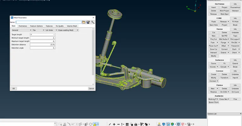
Fig: Mesh Parameters are set.
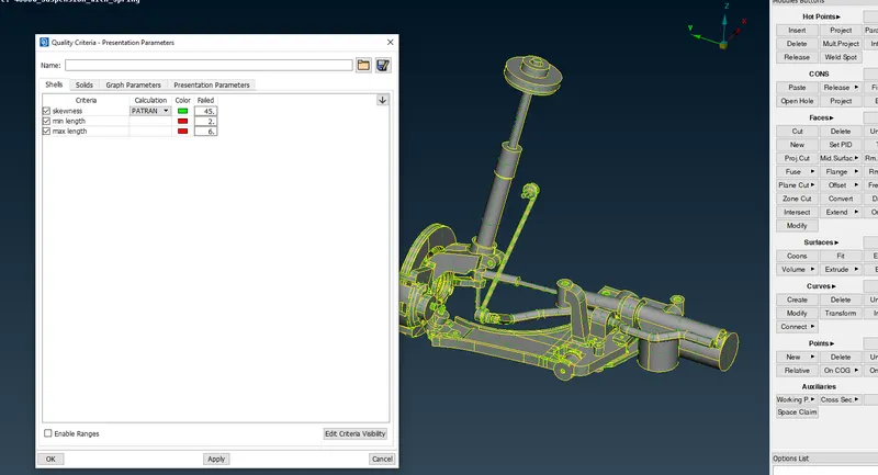
Fig: Quality parameters are set.
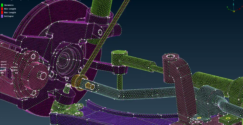
Fig: All the parts are shell meshed and PID is set separately.
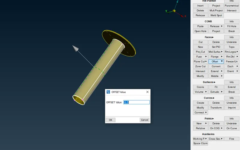
Fig: Midplane is generated for uniform parts with PID setting and thickness assignment.
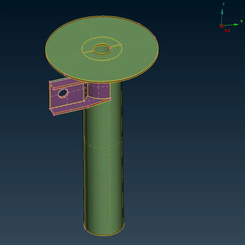
Fig: Transparency ON for parent object for Mid plane check.
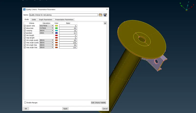
Fig: Quality parameters are set.
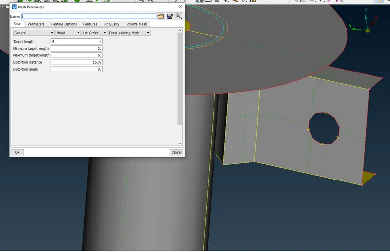
Fig: Mesh parameters are set.
Note: Here mixed mesh elements are used.
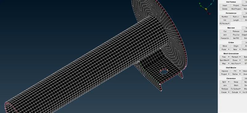
Fig: Shell elements are drawn as Solids.
STEP 3: Volume meshing.
Process steps include
Defining the volume and setting PID as PSOLID property card>> Generating Unstructured mesh >> using grid options like move free and move to correct TET Collapse errors
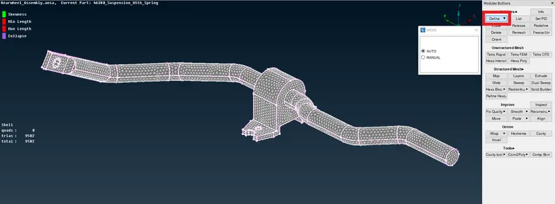
Fig: Volume is defined
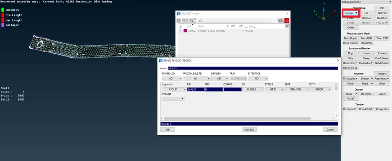
Fig: PID is set
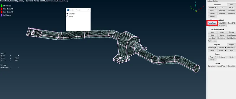
Fig: Tetra Rapid is used as an unstructured mesh option
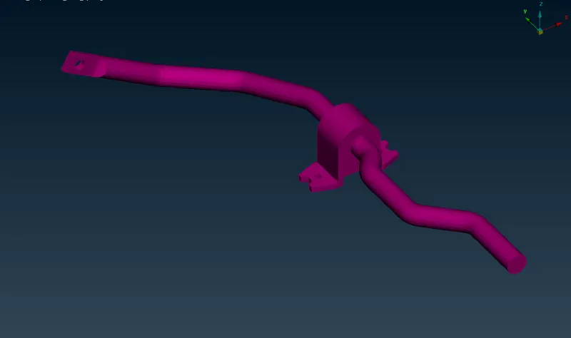
Fig: Meshed Volume elements
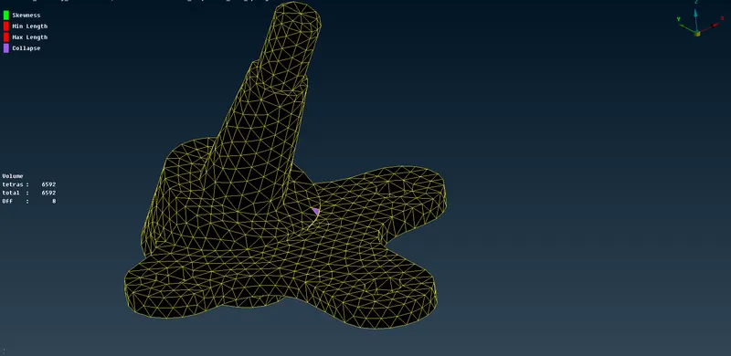
Fig: OFF elements obtained.
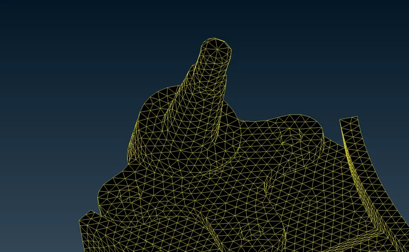
Fig: OFF elements are corrected by using various grid options
Similarly, all the parts are volume meshed
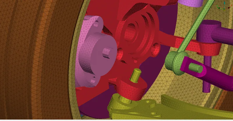
Fig: Volume mesh is obtained for all the assembly parts
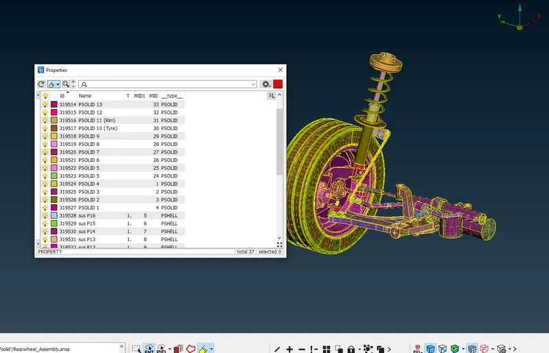
Fig: Gradient view for proper mesh and geometry check
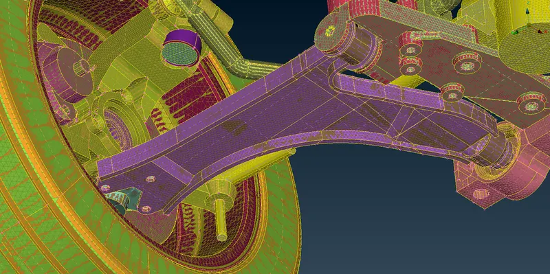
Fig: Another view for a proper check.
Note: For elements like springs midplane and volume meshing is not considered a good idea. Now, we enter the Nastran Deck to represent spring as
PBAR element with proper thickness.
Process includes
Generating middle curve in the spring>> Setting element ID as PBAR and specifying element length>> Realising spring by using line elements drawn as solids in presentation parameters
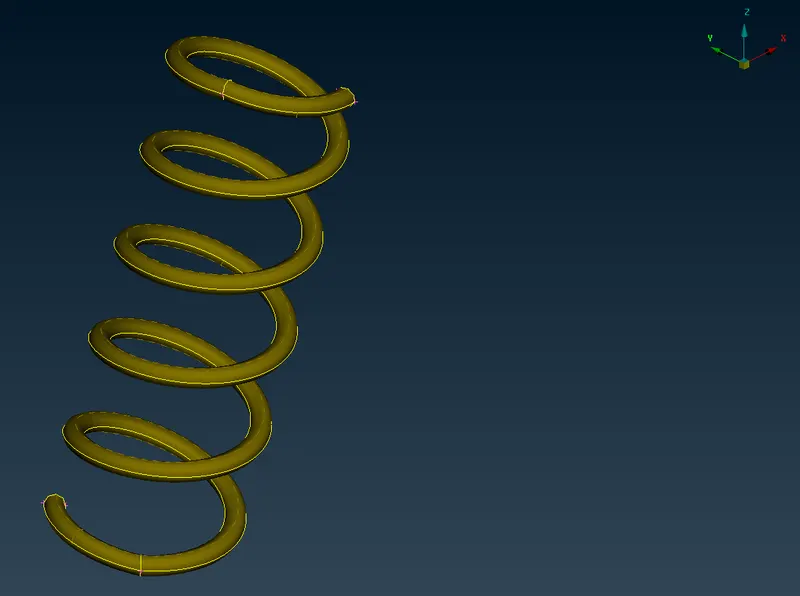
Fig: Spring parent geometry
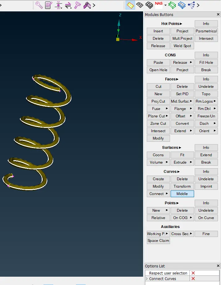
Fig: Selecting cuts for middle curve generation
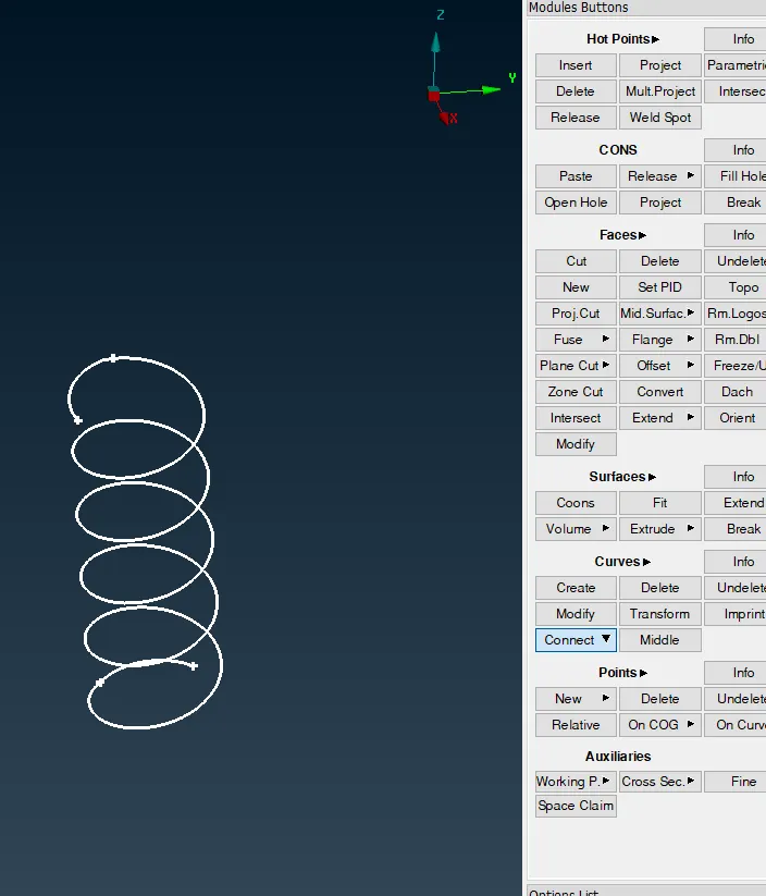
Fig: Middle curve is generated and connected to form one single geometry
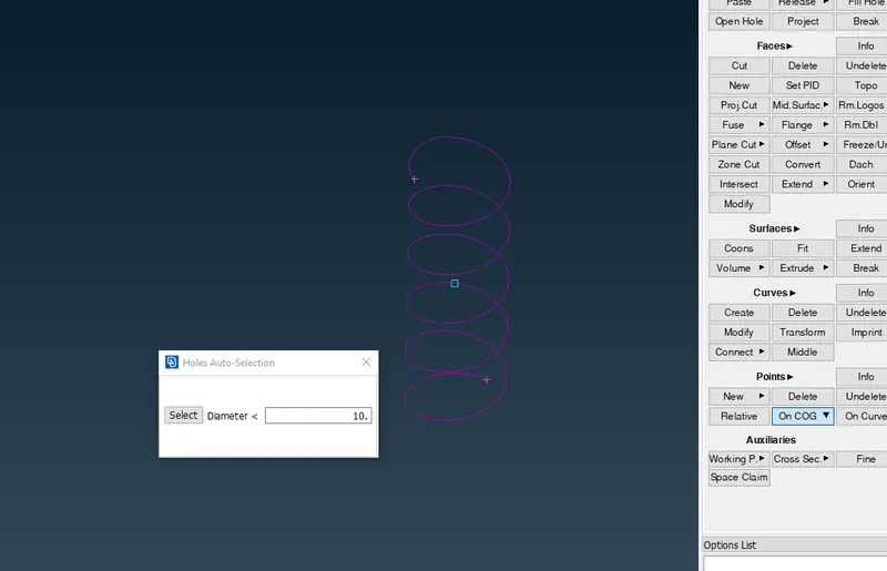
Fig: creating point on COG
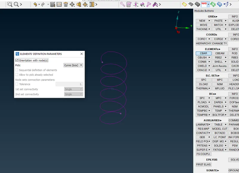
Fig: Setting element orientation
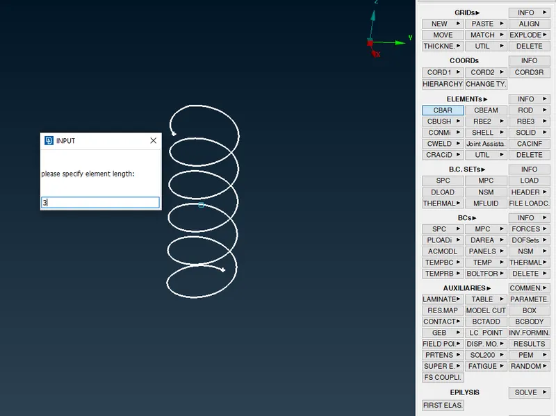
Fig: Specifying element length
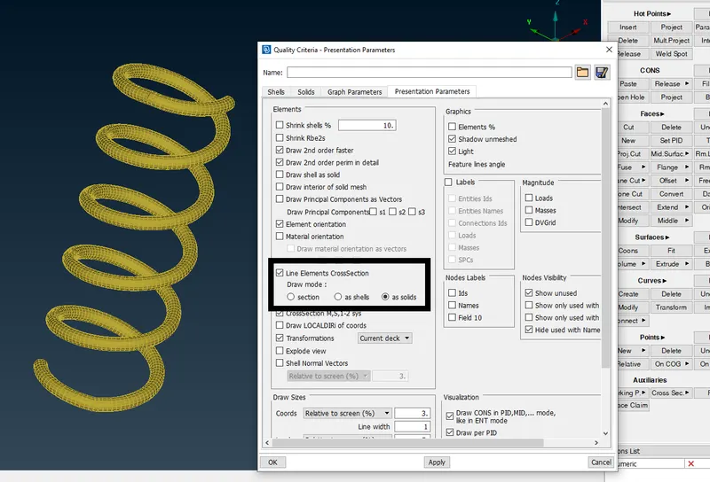
Fig: Showing line elements as solids
STEP 4: Setting up connections
Single Node and many node RBE2 elements are used under Nastran deck for connecting various FE elements as required.
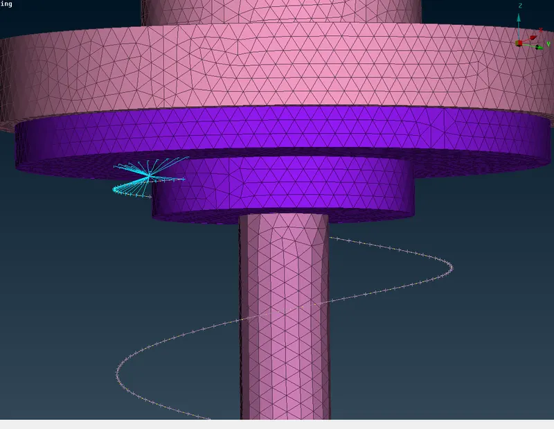
Fig: Connecting spring elements with many node RBE 2 elements

Fig: Using many node RBE2 element for top side of hole in one PID and bottom side of hole in another PID , later two master nodes are connected using two node RBE 2
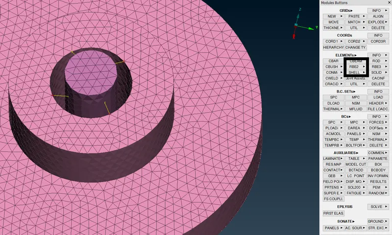
Fig: For circular contacts, two nodes RBE2 elements are used in four directions.
Now, Seam weld connection needs to be established in the parts shown below.
Major steps include creating weld data << converting data to seam weld connection << setting belt PID and weld geometry
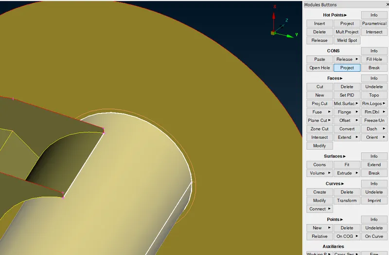
Fig: Projecting cons for middle curve generation
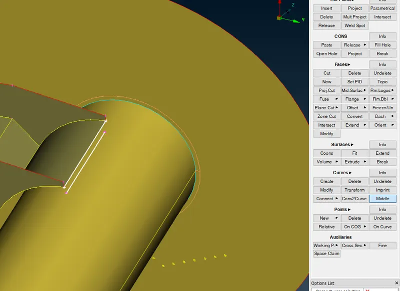
Fig: Middle curve is generated
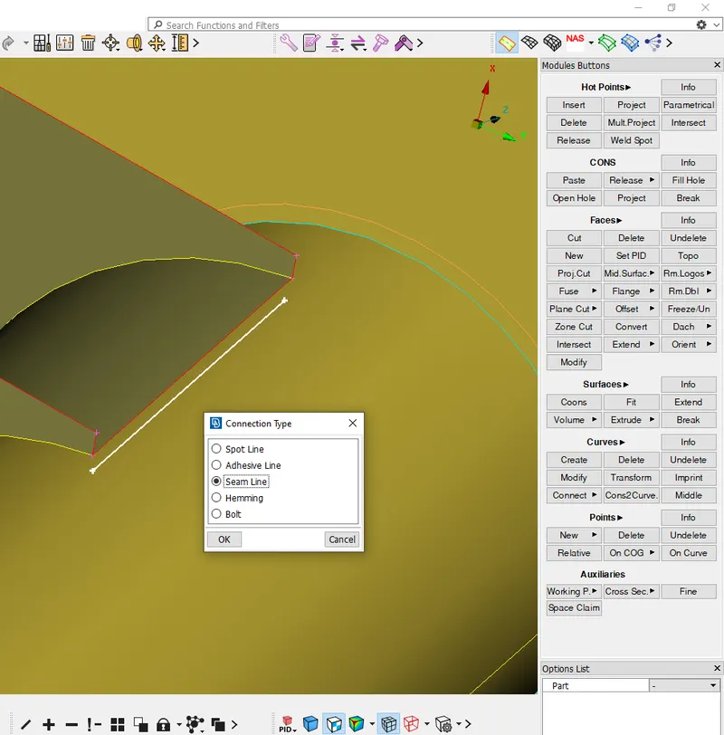
Fig: Converting curve to seam line
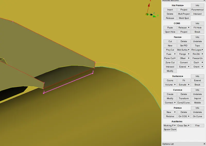
Fig: Seam line is realised
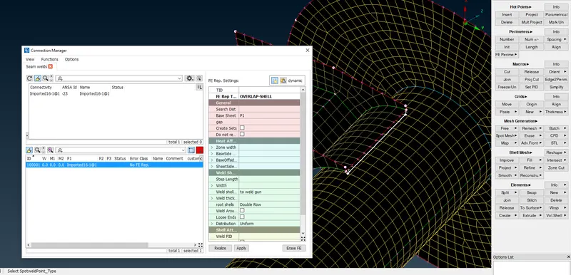
Fig: Setting part 1 and part 2 as parts to be joined by seam weld
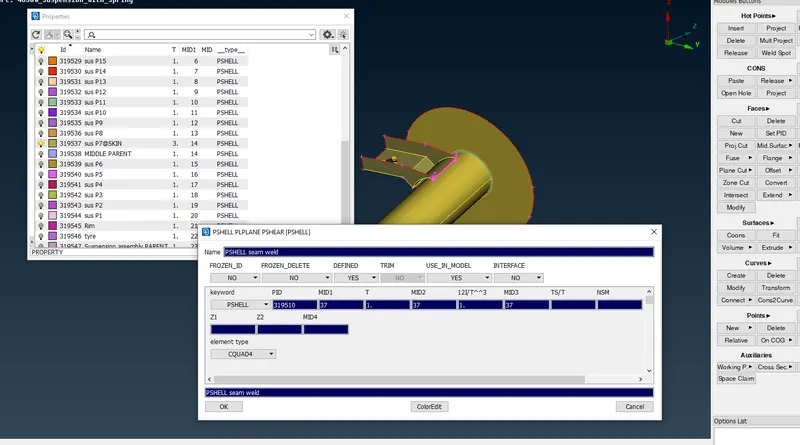
Fig: Setting weld PID
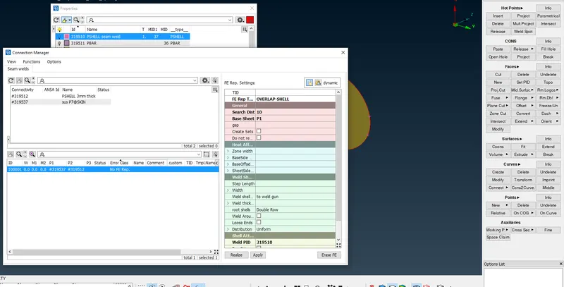
Fig: Realising Seam weld
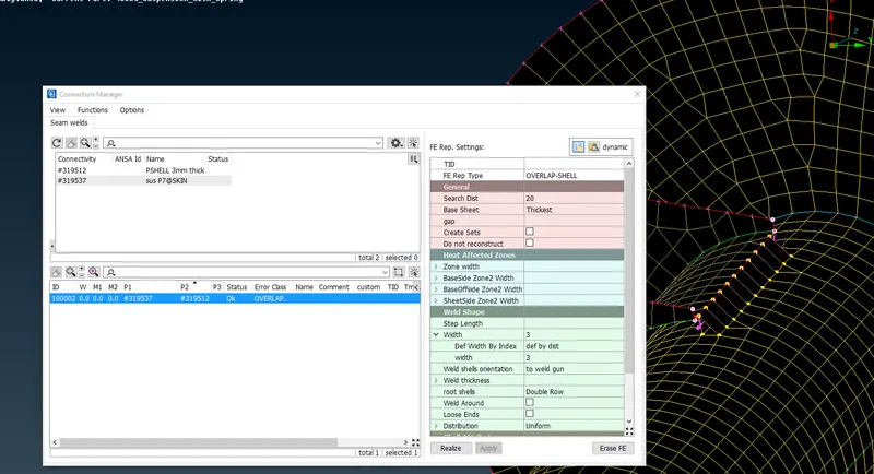
Fig: Seam weld connection is realised
Now, Symmetry command is used to copy the gemetry and FE
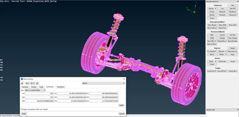
Fig: Performing symmetry
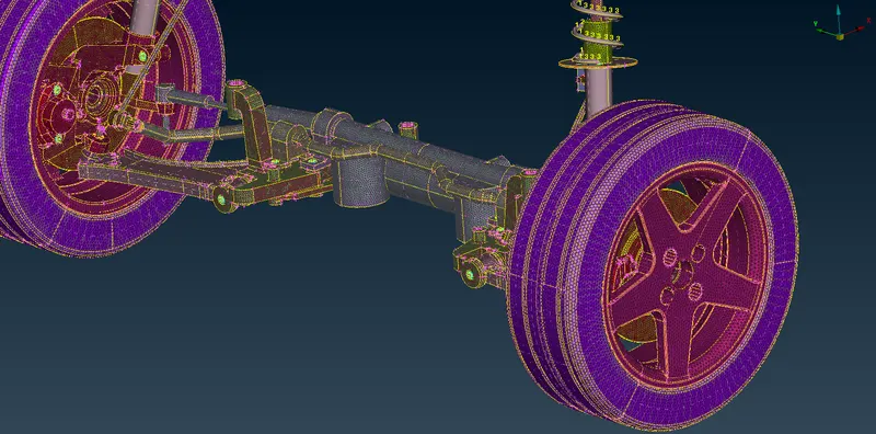
Fig: complete set-up is realised
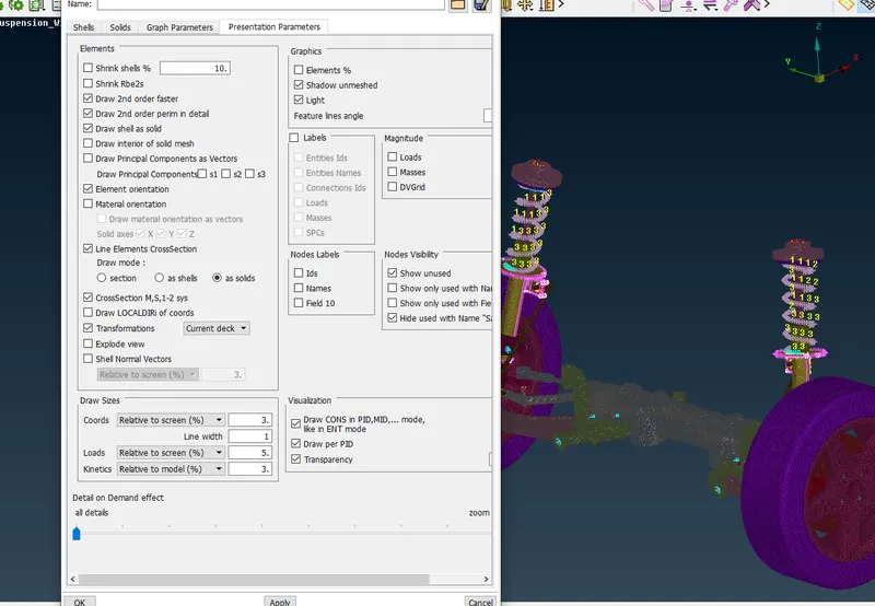
Fig: setting presentation parameters properly
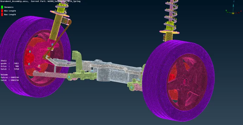
Fig: Gradient view
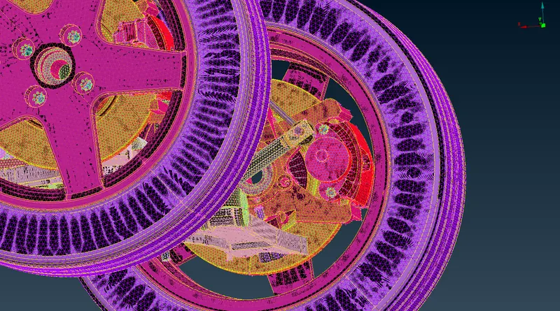
Fig: Gradient view 2
CONCLUSION:
1. ANSA is a versatile tool which lets you complete your objectives in custom steps and desires method.
2. For uniform parts with thickness less than 5 are best suited for mid planing and meshing with mixed elements.
3. Performing Symmetry along a plane helps mirroring not only parent body but Fe elements, volume and connection as well which makes it a lot easier to achieve objective.