Week 3 - 2D meshing for sheet metal
AIM: To create the mesh on the mid surface of the components in a Hood model. The process starts with performing topology along with geometry cleanup and geometry checks for correcting any triple cons, generating mid surface using a suitable method, and meshing the components following suitable quality parameters.
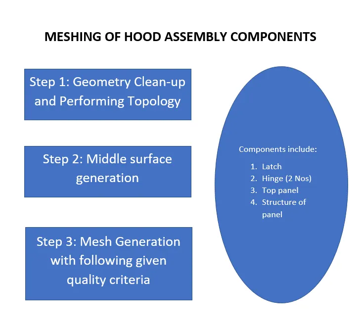
FIG: Basic Methodology
A: GEOMETRY CLEAN UP AND TOPOLOGY
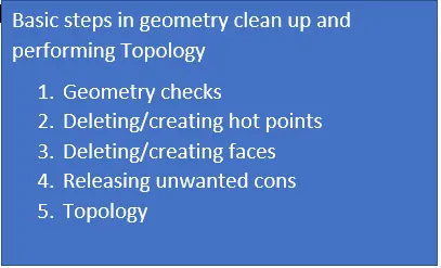
FIG: Basic options
Below are the components of hood assembly parts with and without TOPO cleanup and final geometry checks
1. TOP PANEL
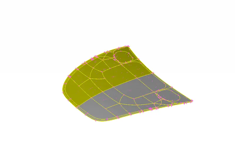
At first, the face is oriented for Positive on the outer surface and negative inside the closed volume surface using the Faces-Orient-Visible command.
Later geometry is checked for any Triple cons and geometrical errors then geometry cleanup is performed using various commands like deleting hot points, deleting faces, and generating new faces. An example is shown below
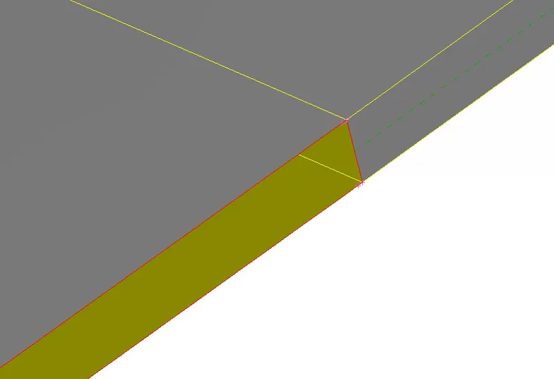
FIG: Face delete
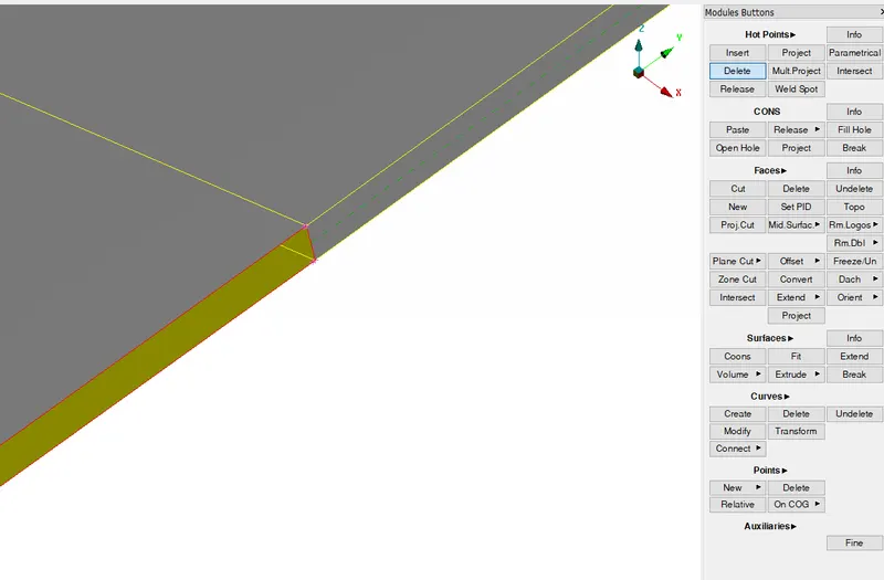
FIG: Deleting hot points
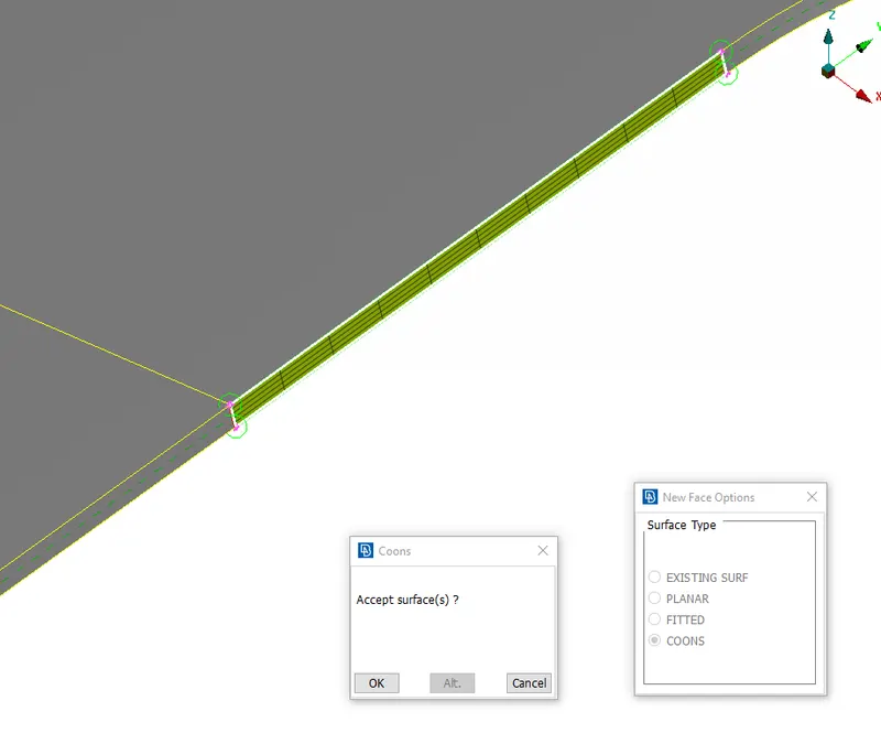
FIG: New face generation
After Geometry cleanup, a geometry check is performed on the part
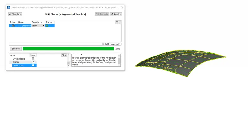
FIG: Geometry check
Now topology is performed to get the Final part for generating mid surface
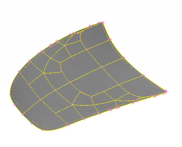
NOTE: All the actions are performed on the other parts of the hood assembly to further proceed for mid surface generation
2. Structure of Panel
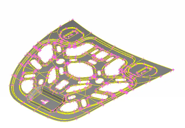
FIG: Before Geometry check and cleanup
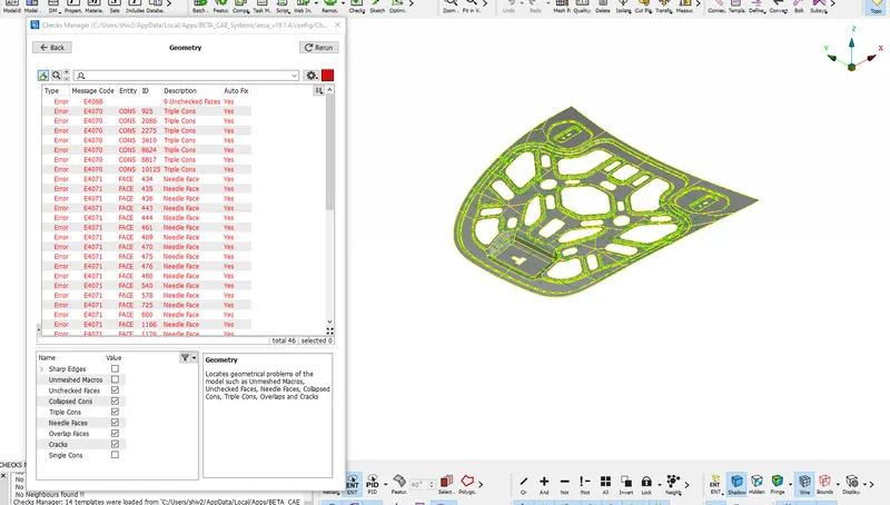
FIG: Errors in geometry
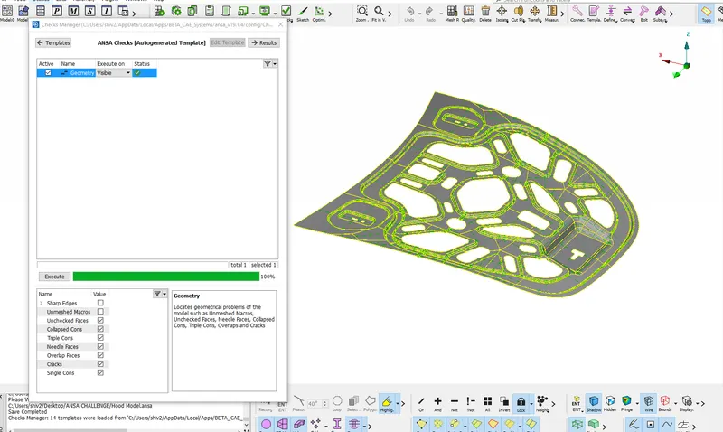
FIG: Geometry check after geometry cleanup and topology tools
3. LATCH
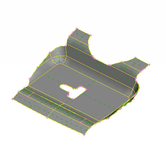
FIG: Before geometry cleanup
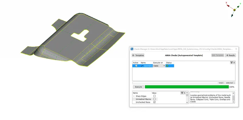
FIG: Geometry check and topology is performed for mid surface extraction
4. HINGE
NOTE: There are total two hinge present, geometry check and topology is performed on both of them individually
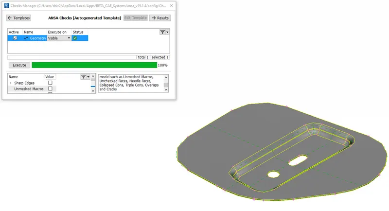
FIG: Geometry check and topology is performed
B. MID SURFACE GENERATION
After the geometry check is done, the mid-surface needs to be generated for all the components. Two types of options for mid-surfacing include manual mid-surfacing and automatic mid-surfacing using skin option in faces mid surface option. In manual mid-surfacing, thickness needs to be assigned using the set Pid option in faces options.
in an automatic mid thickness, value is assigned automatically. Automatic mid-surfacing is done for all the components due to minor complexities in the models. the mid-surfacing of Latch is shown below for reference same steps are involved for all the other components.
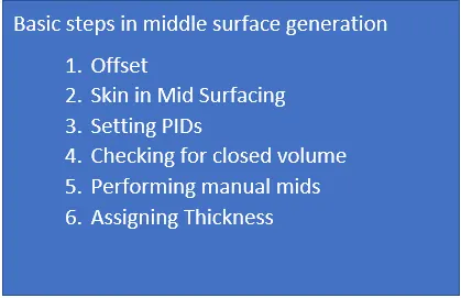
FIG: Basic Options
1. LATCH
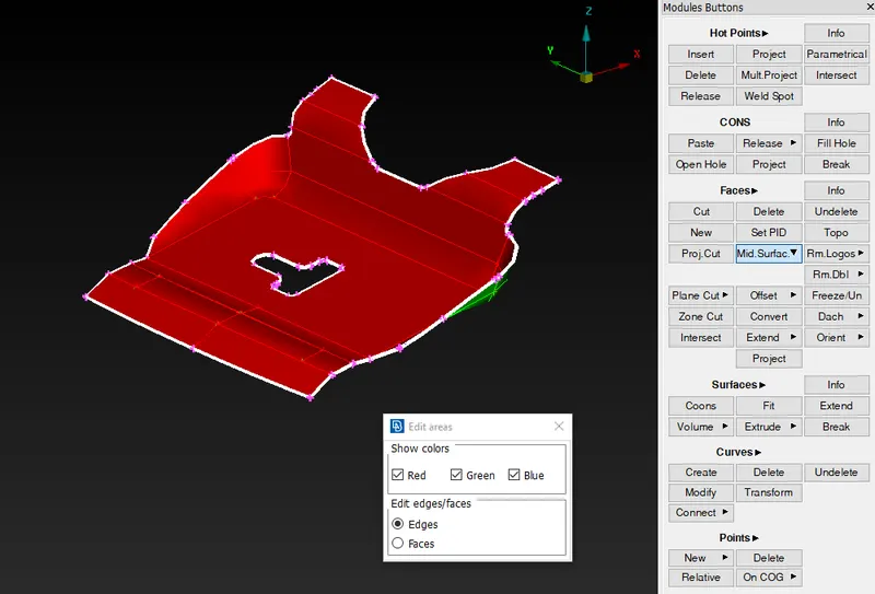
FIG: Automatic mid
After selecting the component for the skin option color on faces for reference of positive, negative, and width face is shown by three different colors. After that offset value is asked and thickness is assigned.
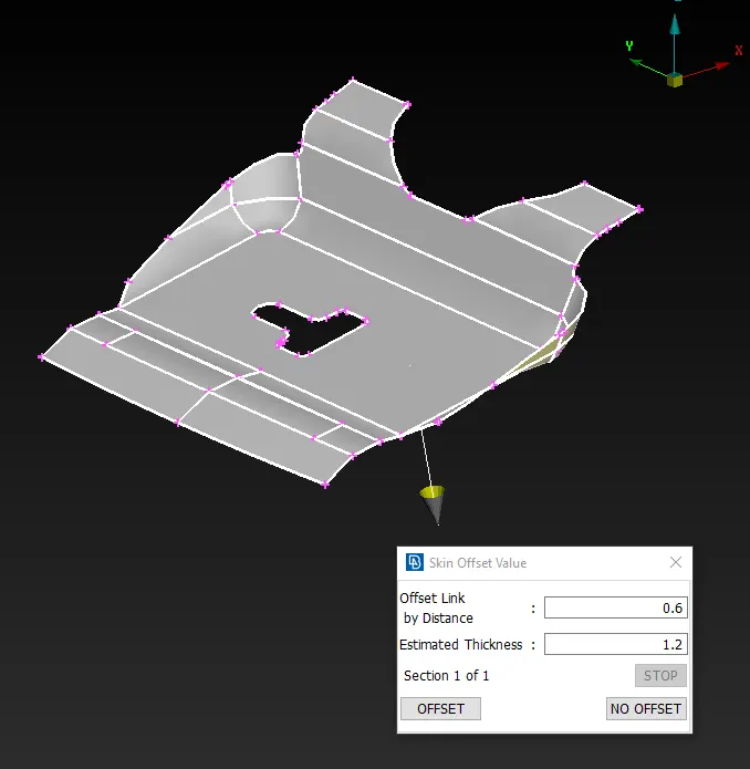
FIG: Checking offset value to set thickness in PID
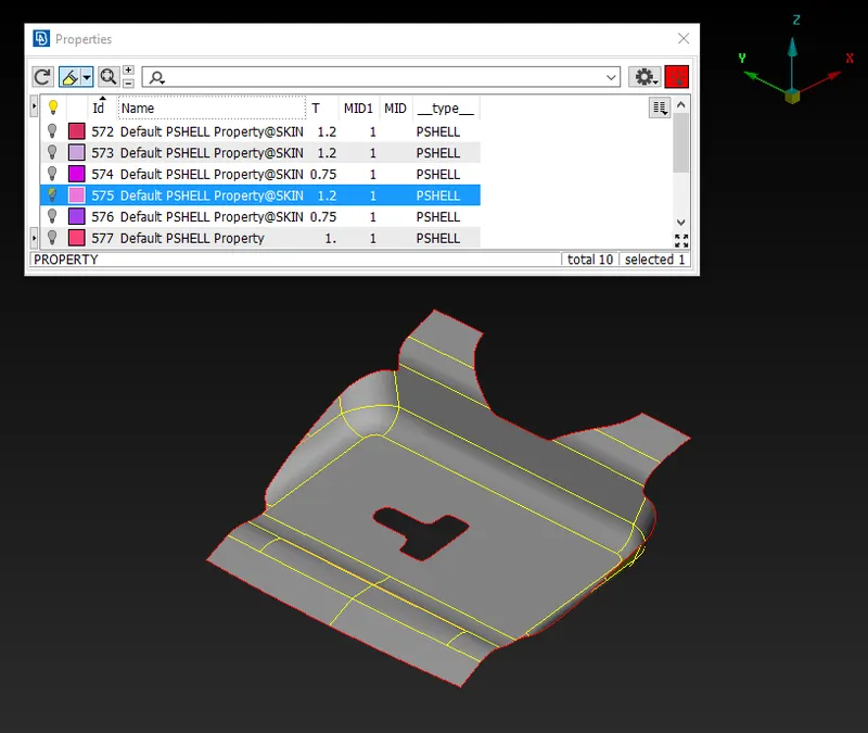
FIG: PID with thickness allowed to mid surface
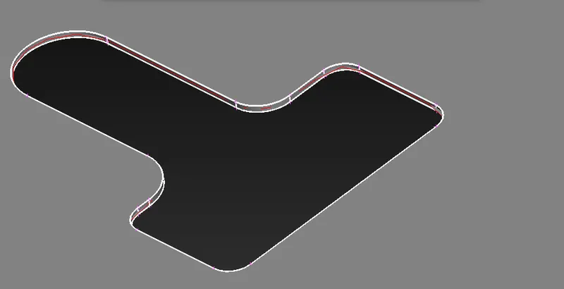
FIG: Middle surface check
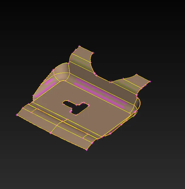
FIG: transparency ON for parent geometry
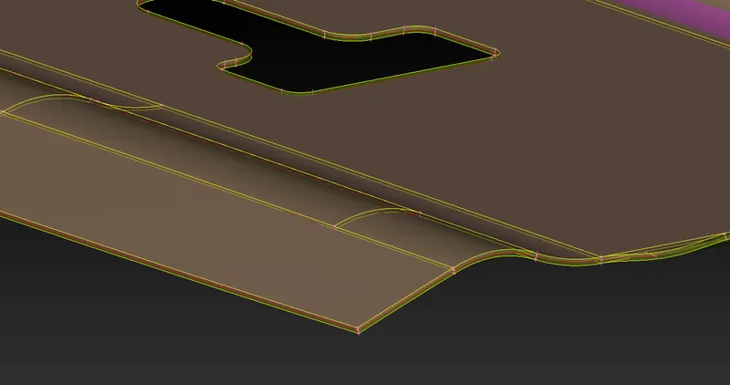
Images with Transparency ON for parent object to understand the correctness of midplane generated. The same steps are performed on all the other parts with images shown below
2. HINGE
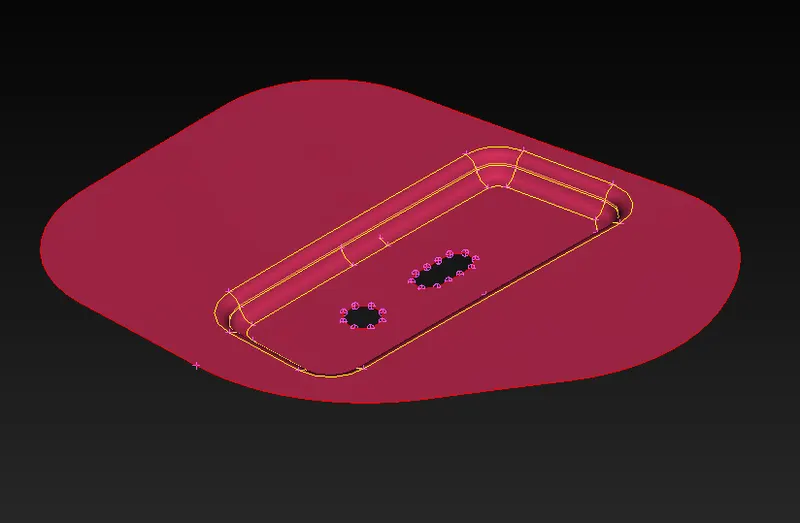
FIG: Mid surface
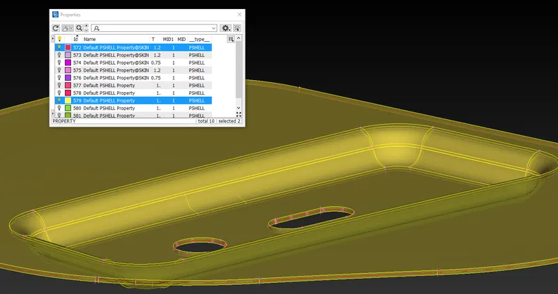
FIG: PID with thickness allotted and transparency ON for parent part
3. TOP PANEL
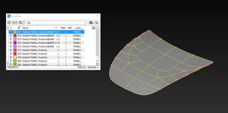
FIG: Top panel mid surface with PID and thickness allowed
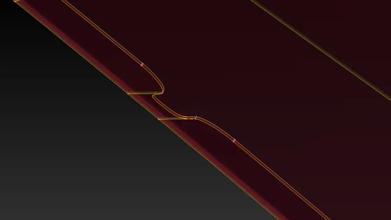
FIG: Mid surface with transparency ON for parent geometry
4. STRUCTURE OF PANEL
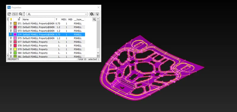
FIG: Mid surface with PID set and thickness assigned
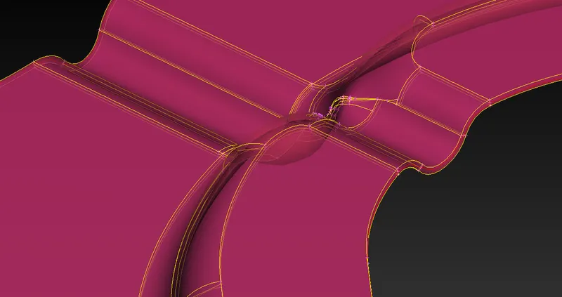
FIG: The transparent parent body for checking mid surface correctness
Now, all the constituent parts of Hood assembly are completed till the process of geometry cleanup, Topology, Geometry check, mid surface generation, and thickness assignation. It's time to start with meshing.
C. MESH GENERATION
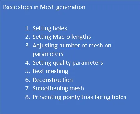
In pursuit of discretizing the parts in finite elements for further study, there are many steps to be performed on the model like setting required quality parameters, assigning length to macros and minimum-maximum length, cutting and joining macros, adjusting the number of elements on parameters for retaining triangular elements as minimum as possible.
All the steps are described using a single part which is later applied to all the parts, first, some common steps are performed
1. HINGE
a) Quality parameters: using the F11 shortcut, the option for setting quality criteria is opened. All the required parameters are put in as per the challenge. presentation parameters are also changes.
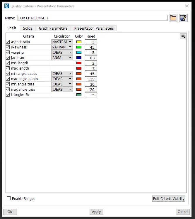
FIG: Shell quality parameters
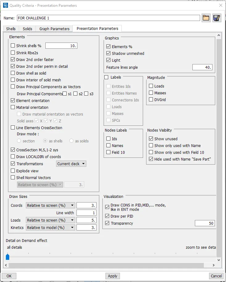
FIG: Presentation parameters like all details option for detail on demand effect and elements percentage in graphics tab is turned on.
NOTE: The quality parameters for reference can be saved using the savefile option in the top right corner of the quality parameter window. In this challenge, it is saved under name of "FOR CHALLENGE 1" so that there is no need to put parameters every time you open ANSA. it is saved as (.ansa_qual) file
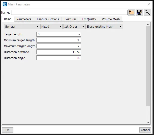
FIG: Mesh parameters are set and saved as (.ansa_mpar) file
b) Setting length: In Parameter tab under mesh module: ANSA asked for window selection first including options as parameters and macros for inside features and holes. Both are set to 5.
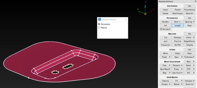
FIG: Window selection
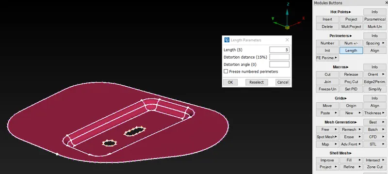
FIG: Setting length
c) Setting up holes for proper mesh generation
Holes are marked using the mark option in the hot points tab after setting the number of elements on macros in even number and sliding them in alignment to the nearest parallel hot points to avoid triangular elements.
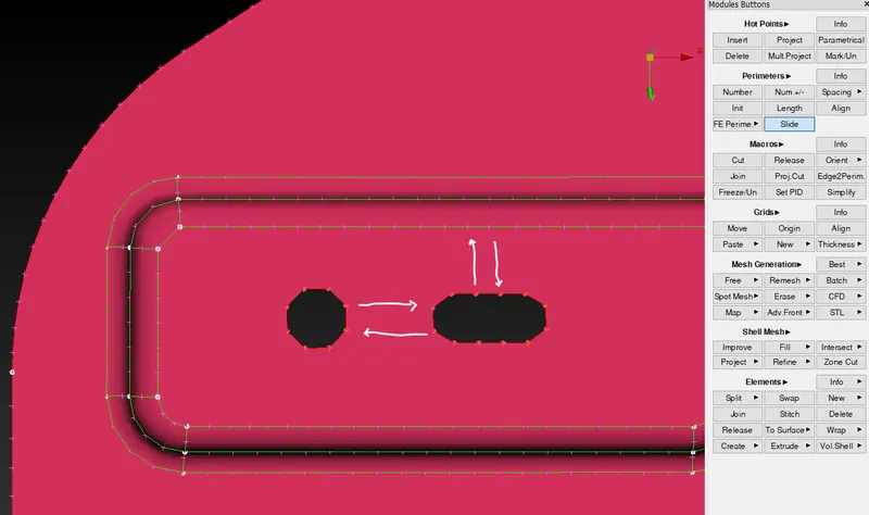
FIG: Alignment of Holes
d) Macro cut and mesh generation: It is advised to cut some planar sub-parts parts of the main part excluding features to create a proper mesh flow along with adjusting a number of elements on new parameters. it is not the best practice but gives us good results. After cutting surface local mesh is generated using the BEST mesh option in the mesh generation tab along with reconstruction and smooth options under the shell mesh tab to adjust the quality parameters.
Step by step process is discussed below.
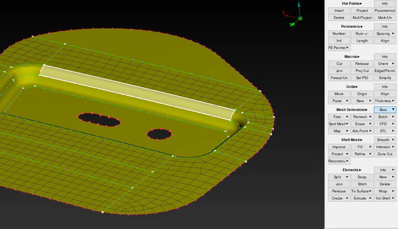
FIG: Macro cut and meshing using best mesh method under mesh generation tab
Note: Green lines separate some properly defined macro-areas for tria-free meshing
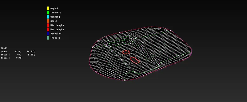
FIG: Checking for quality criteria and proper mesh in hidden mode.
After the complete part is meshed with maintaining quality criteria, macro cuts are joined using keep mesh options to ensure no reconstructions
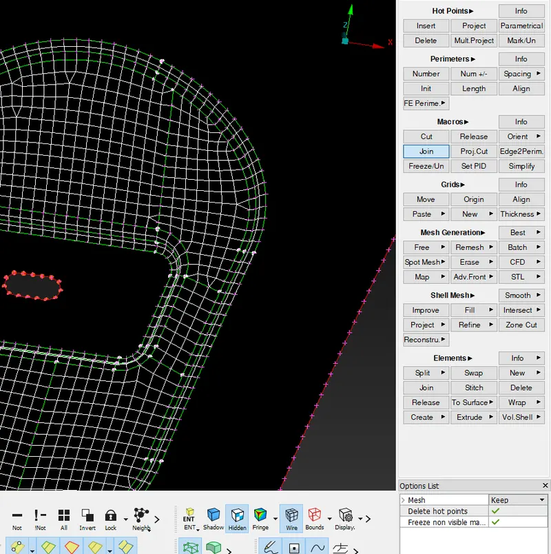
FIG: Macro cuts are joined using keep mesh under option list shown in the figure
Later reconstruction and smoothening mesh can be used to further enhance quality criteria, below is the shown advantage
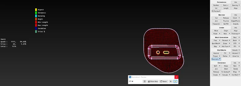
FIG: Before reconstruction
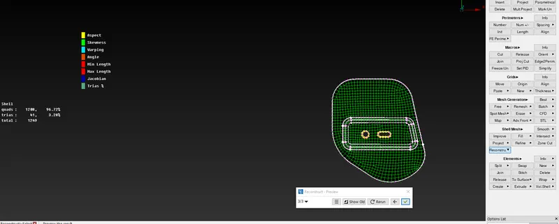
FIG: After reconstruction
Note: Tria percentage is improved 5 percent approx to 3 percent approx.
now, after the mesh is generated with proper practices. Draw shells as solids are enabled in the presentation parameters tab. Later in PID mode with enabling the parent geometry, the gradient view is checked to ensure proper meshing.
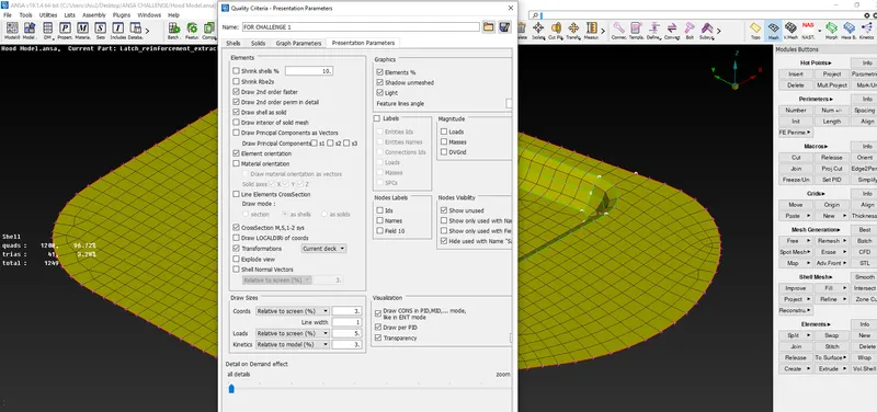
FIG: Draw shells as solids
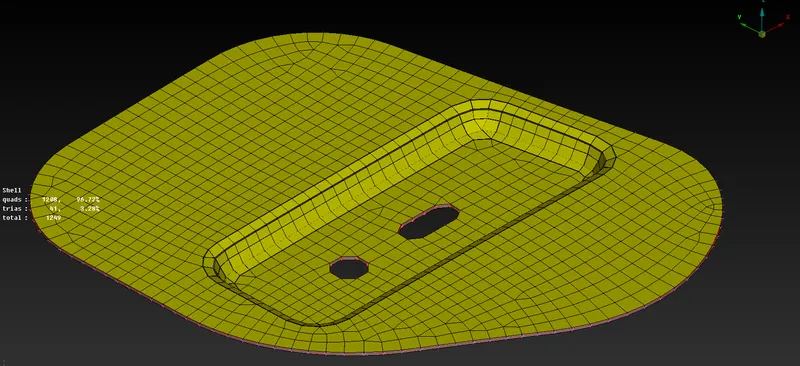
FIG: Output mesh
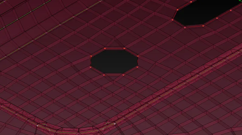
FIG: Mesh with transparency on for mid surface
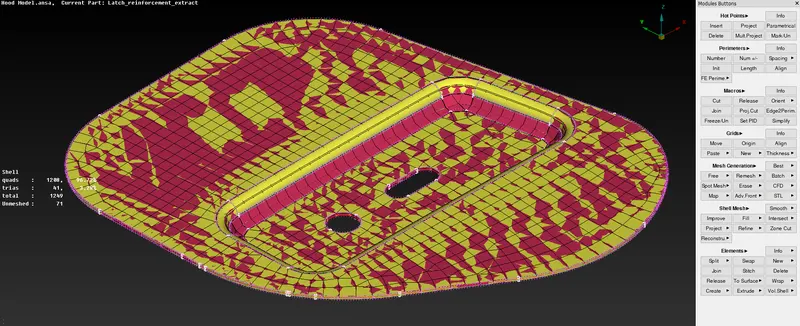
FIG: Gradient in PID mode with visibility enabled for meshed mid surface and parent geometry
NOTE: The same process is performed for all the remaining parts.
2. LATCH
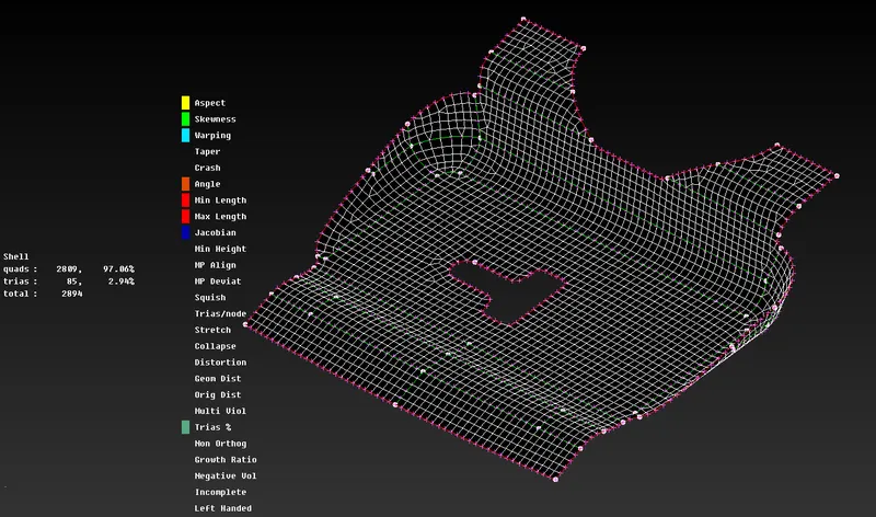
FIG: Mesh generation
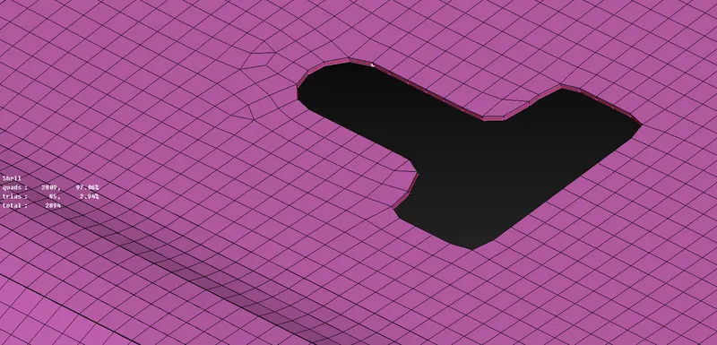
FIG: Draw shells as solids
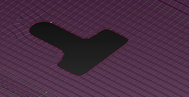
FIG: Mesh with transparency for mid surface
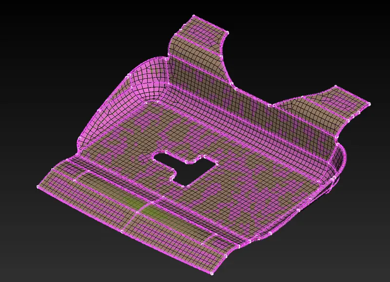
FIG: Gradient view
3. TOP PANEL
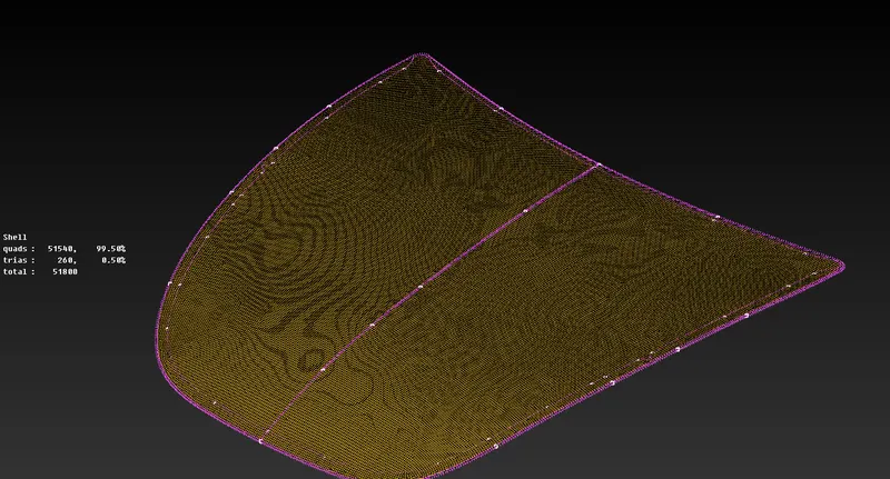
FIG: Top panel mesh
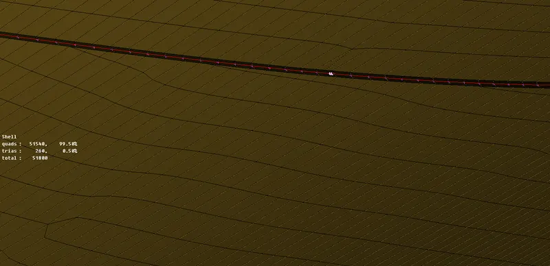
FIG: Draw shells as solids
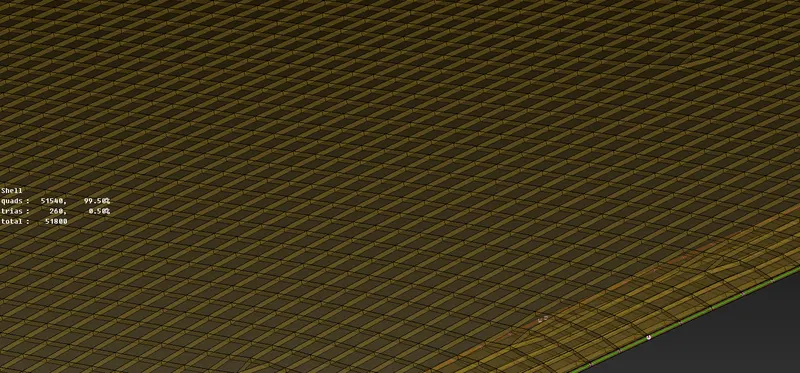
FIG: Transparency on
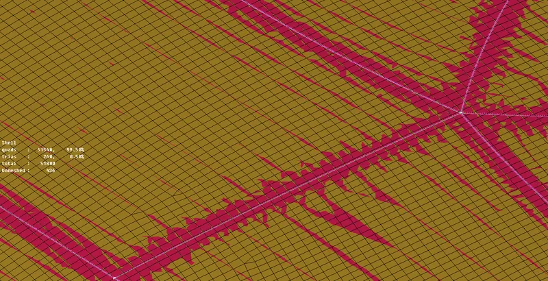
FIG: Gradient view
4. STRUCTURE OF PANEL
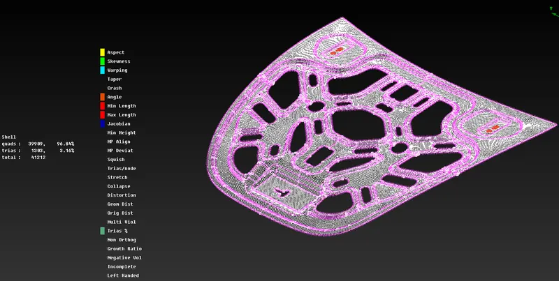
FIG: Mesh generation
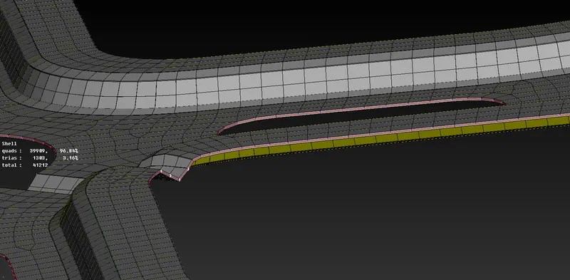
FIG: Draw shells as solids
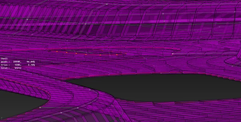
FIG: Transparency ON
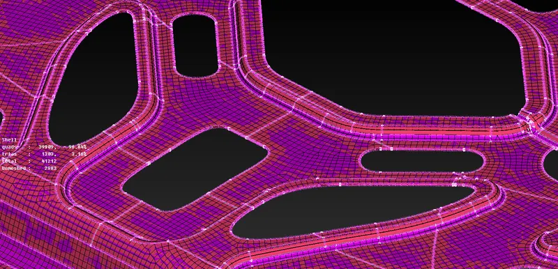
FIG: Gradient View
CONCLUSION:
ANSA is a pro-tool to generate a mesh and full preprocessing.
Topology and mesh tools are widely used in this challenge
ANSA provides two methods for the mid-surface generation which enables versatility.
while meshing the least number of tria elements must be ensured along with no pointy tria elements on macro features as well as on fillet features.
Any complex part can be meshed by separating it with some macro cuts.