Week- 5 - Solid meshing
AIM: To create solid meshing of Rear-View mirror of an automobile using Tria elements throughout the volume.
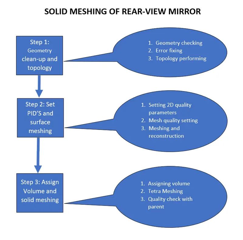
Step 1: Geometry clean-up and topology
Whenever a component or assembly is given geometry check to avoid any defects and distorted faces are done. Later, Topology is performed to create separate macros along the body for proper meshing.
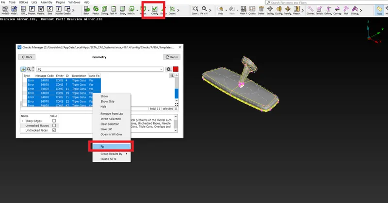
Fig: Fixing the geometry errors after topology is performed
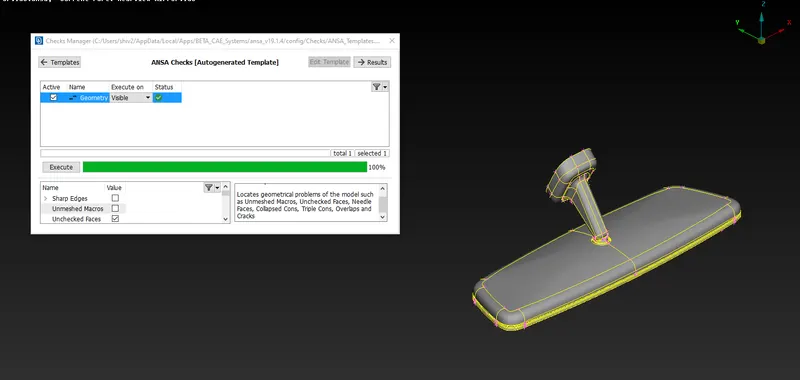
Fig: Geometry check successful
Step 2: Setting PID and surface meshing
After the geometry is ready for surface meshing, quality and mesh parameters are entered, parametric and macros are set to target length then surface meshing is done with tria as well as ortho-tria elements along with reconstruction for proper mesh flow.
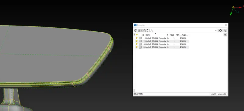
Fig: Default PID'S are set to different parts however while solid meshing different PID'S will be allocated to volumes.
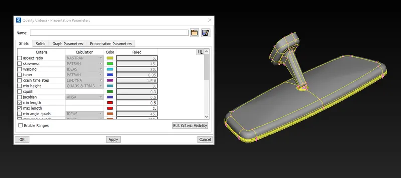
Fig: Here minimum and maximum length are taken as 2D mesh quality parameter
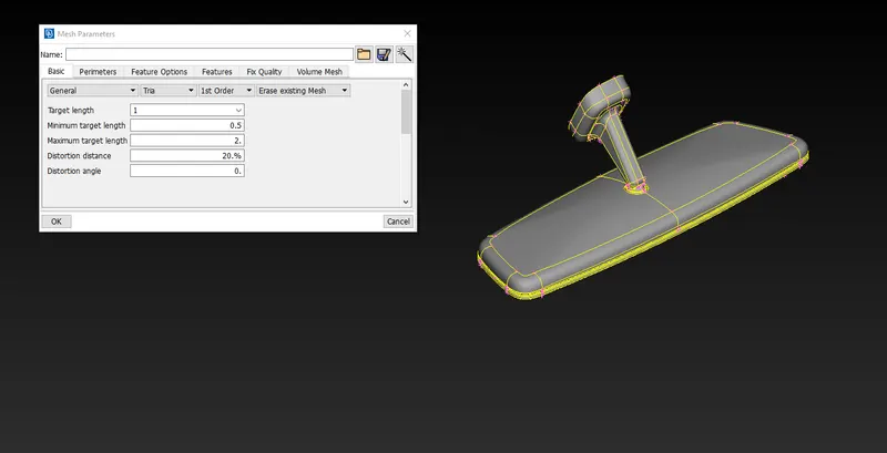
Fig: Mesh Parameters are set for the component before meshing.
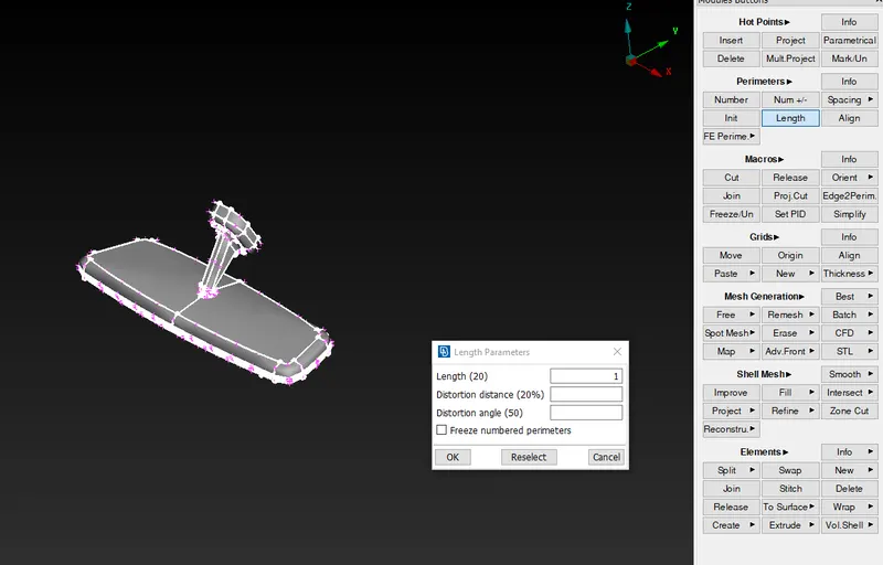
Fig: Target length for parameters and macros is set to unity.
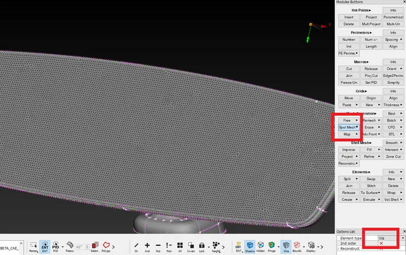
Fig: Spot mesh command is used to create the mesh with "Tria" elements, they are best suited for flat surfaces.
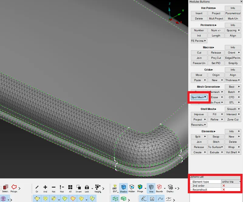
Fig: Spot mesh command is used to create the mesh with "Ortho Tria" elements, they are best suited for curved surfaces. Ortho tria elements best capture the rounded features like fillets.
Step 3: Listing Volume and solid meshing
After surface mesh, we are going to map the mesh throughout the volume with "Tria" elements. In the process, the parts are to be listed as volumes because ANSA only considers it as a volume unless we define it. Later quality parameters will be set and solid meshing will be performed using a suitable algorithm. Finally, quality must be ensured by avoiding any dents, troughs and comparing volume with the parent.
Note: We enter to the VMESH module for solid meshing. A new PSOLID card is used for setting PIDs.
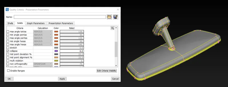
Fig: 3D Quality parameter is set.
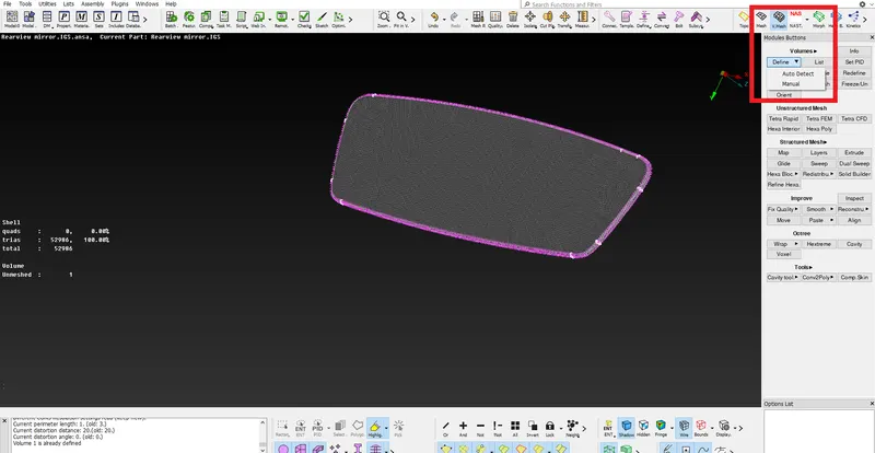
Fig: Volume is defined under Define-manual-auto with double click confirmation.
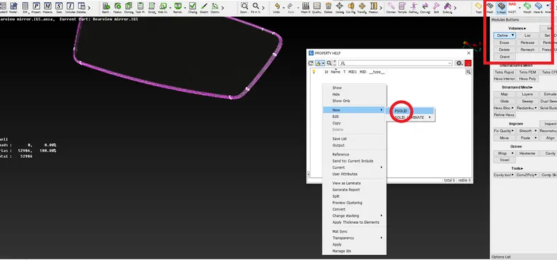
Fig: PSOLID card is set to the particular component.
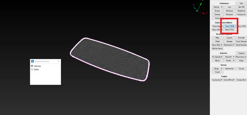
Fig: Volumetric mesh is created with the tetra FEM option. Tetra options can also be used in various situations. Tetra FEM creates tetrahedral mesh.
Similarly, all the other components are given separate PIDS with solid meshing.
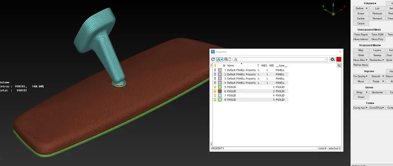
Fig: All the components of the assembly are meshed with different PIDs.
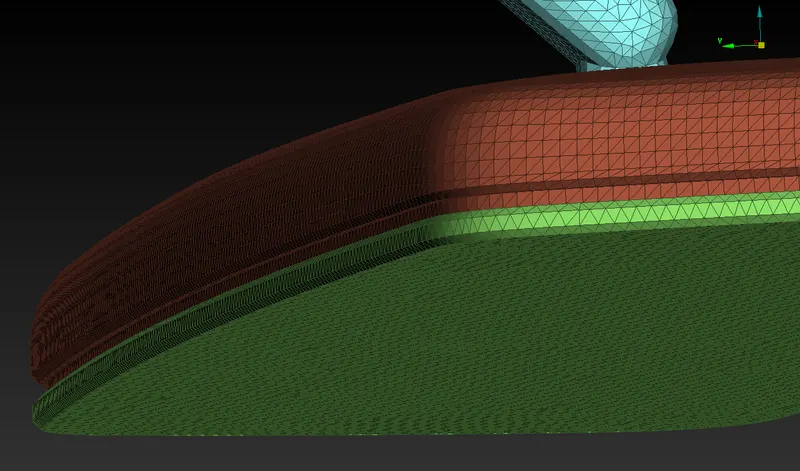
Fig: Volume is closely checked for kinks, dents, and other defects.
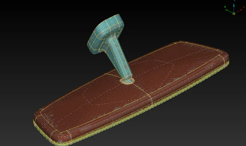
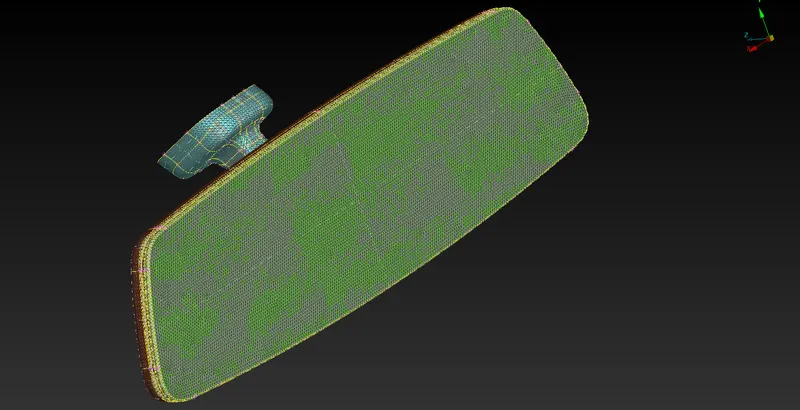
Figs: Gradient view is checked for feature coverage by volume mesh with parent geometry.
Conclusions:
1. In solid meshing Property card used is called as PSOLID.
2. There is no need to extract mid-surface because of the absence of thickness.
3. In volume meshing, mesh elements are mapped from one form face to another by using growth algorithm.
4. For complex curved surfaces, ortho-tria elements capture features with more accuracy.