Week 4-1D Element Creation Challenge
OBJECTIVE: The objective of this challenge is to form the mid surface out of the provided geometry and mesh it using a size of five units and later create 1-D elements to the particularly given cross-sections with maintaining the required degree of freedom.
METHODOLOGY USED:
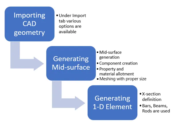
Head Topics are discussed above, we discuss all the steps in detail in sections below
STEP 1: IMPORTING CAD GEOMETRY
Under the import tab, various options are available like import model, solver deck, geometry, BOM, and connectors. The option is selected upon the primary file type available.
Here, we import the geometry and we can choose file type among IGES, Solidworks, or STEP file and click import upon file selection.
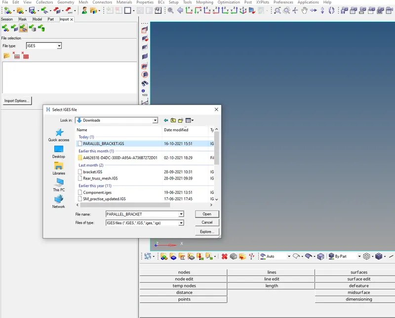
Fig: PARALLEL_BRACKET.IGS is imported.
STEP 2: GENERATING MID SURFACE
The sub-steps includes
- create the mid surface,
- Assign material and property to the components
- Mesh the mid-surfaces with a proper thickness value as that of the parent geometry
Lets us start with mid-surface creation.
Here, we use the Midsurface option under the GEOM tab.
Here we select a particular geometry part to create auto Made auto Made surface it calculates the thickness of the primary model automatically
Note: Auto mid surface option is used in case of visible uniform geometry

Fig: Midsurface option selection
Now, upon selection of upper bracket, we get mid-surface with new component as Middle surface as shown in the left ribbon.
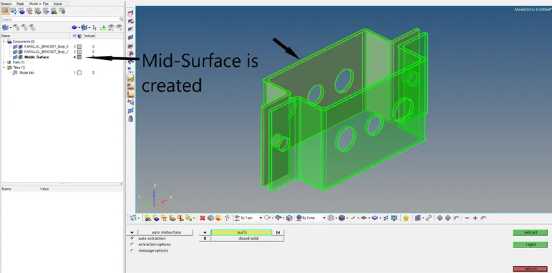
Fig: Middle surface is created
Now, the Point to be noted when we create a mid surface in the parts of the geometry, they tend to get associated with the component created by the system.
therefore, we need to create as many number of components as that of mid-surface created and later the surfaces are associated with the new component created.
This is done by moving the geometry parts using Organise option under the Tools tab.
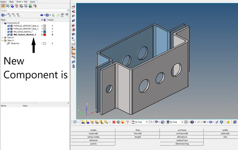
Fig: New component is created by clicking the right mouse button and further clicking the create option.
Note: The new components are renamed and parent geometry is deleted.
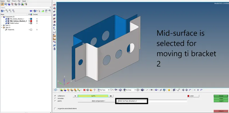
Fig: The lower bracket is moved in the new property created which is named Mid_Surface_Bracket_2.
Now, all the extra components are deleted and we get the mid-surfaces as components.
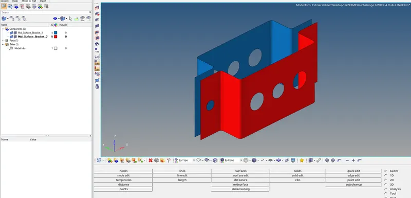
Fig: Components are associated properly.
Now, it's important to associate material and property to the components. Material and property are created by
right mouse button clicks and use create material and property.
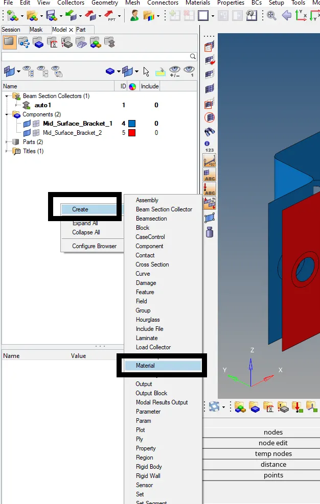
Fig: Material and property creation process.
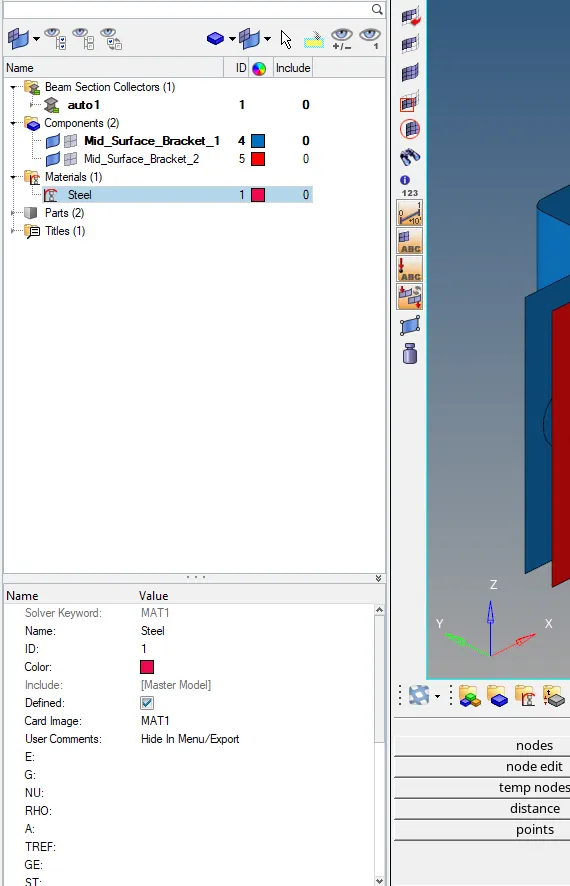
Fig: Steel material is created with card image as MAT 1
Similarly, the property is created and material, components are associated with it.
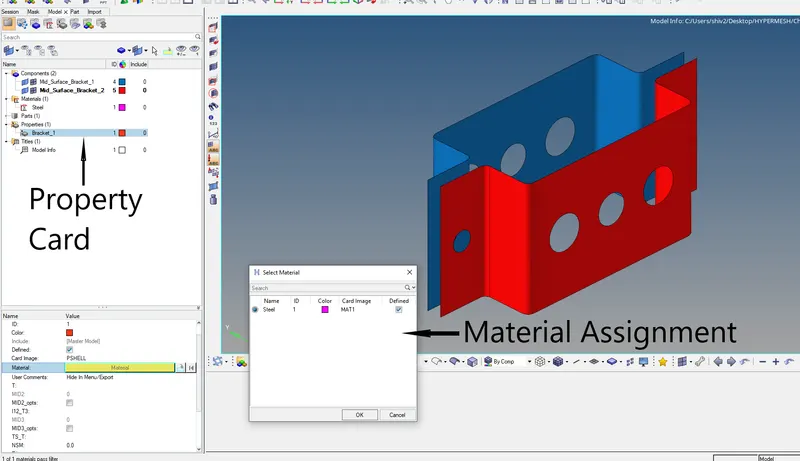
Fig: Property card is created and renamed with inputs specified like material, card image as PSHELL, Thickness, etc.
Note: Here thickness for mid-surface is taken as 2 mm but the final thickness associated with the mid surface will be the actual thickness of uniform geometry which is 5 mm, it can also be done once mesh and elements are created.
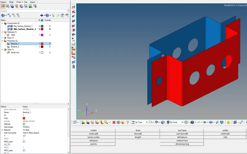
Fig: Property card is created for both of the components.
Now, it's time to associate the property with the components.
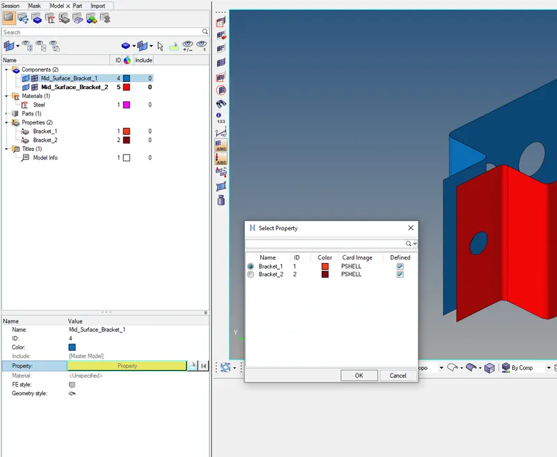
Fig: Property is assigned to components. Material is auto-assigned as we associated it in the property.
Now, before proceeding with meshing geometry preparation is also required. Here we are making washer splits using the quick edit option under the GEOM tab.
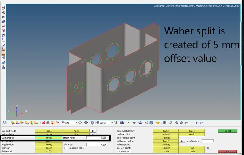
Fig: Washer splits are created around holes for an offset value of 5 mm.
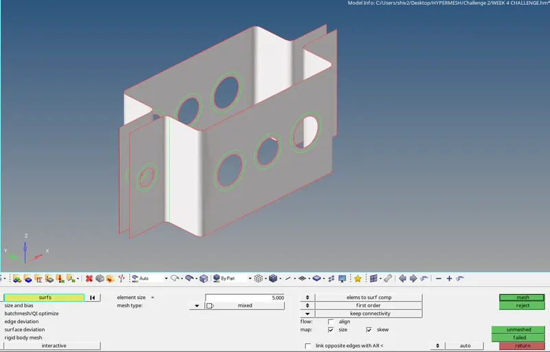
Fig: Mesh size of 5 mm is used with mixed elements type and mesh is created.
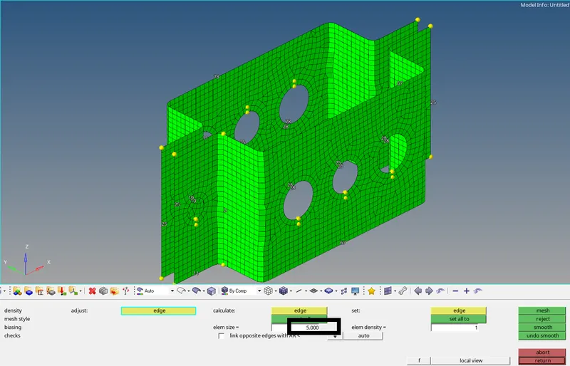
Fig: The number of elements is set equal around the washer splits for proper mesh flow.
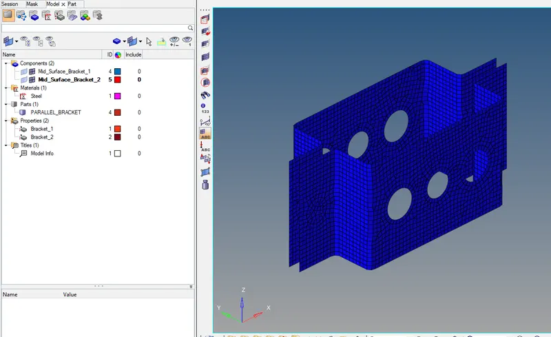
Fig: The second step is achieved
STEP 3: GENERATING 1-D ELEMENT
Here, Hypermesh follows the same methodology to create 1-D elements. Sub-steps includes
- Creating cross-sections for 1-D elements using Hyperbeam option under the 1D tab
- Creating property cards and assigning x-sections and card images
- Creating 1-D elements and updating the required property as per requirement
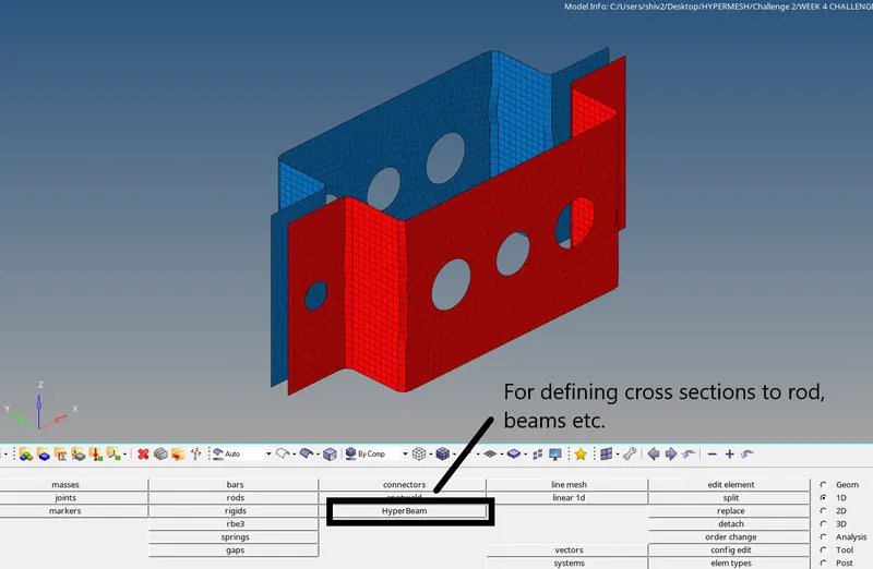
Fig: Opting for Hyperbeam option to define cross-section type
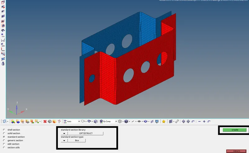
Fig: Under the following steps, optistruct is set as the standard section library.
After "create" is selected, a different Hyperbeam tab is opened, then we create X-sections, select type, and values.
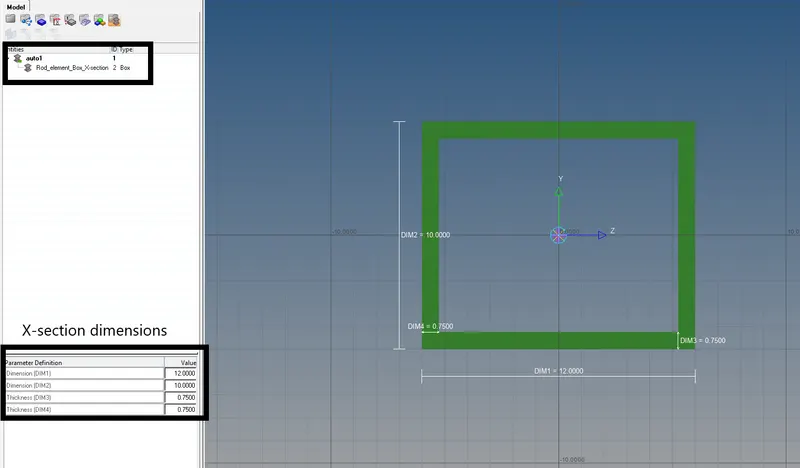
Fig: Rod-element cross-section is defined as Box, geometric values can be seen in the bottom of the left ribbon.
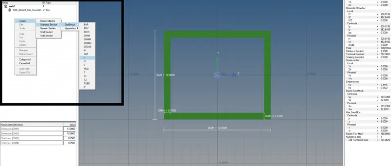
Fig: Similarly, another cross-section is defined for beam as standard "I" section.
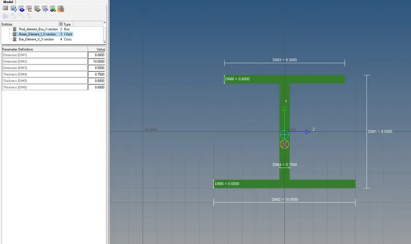
Fig: I section is created for the Beam element.
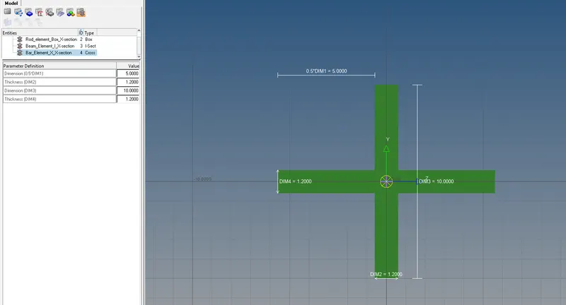
Fig: Similarly, the cross is taken as a cross-section for the bar element to be created.
Now, new properties are created for bar, beam, rod. Later, defined beam sections are associated with the appropriate properties.
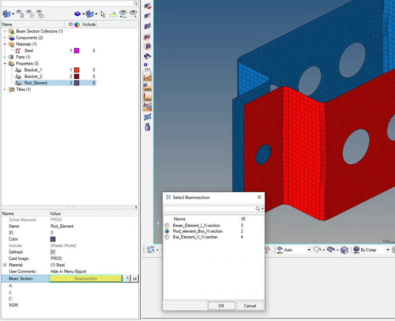
Fig: Property for Rod-element is created and rod element cross-section is associated.
Similarly, other two properties for elements are created.
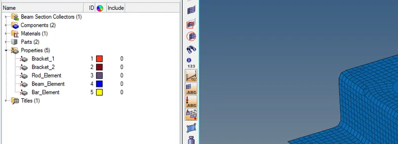
Fig: All properties are created.
Now, To create 1-D elements we need to fix the DOF'S (Degree of Freedom) at two end positions of the element. The DOF's manages how the element is supposed to show motion when the load is applied and where to stay rigid.
So, we generally use RBE2 and RBE3 links to assign DOF to elements depending upon the usage. RBE2 are the rigid elements that have infinite rigidity and the load on RBE2 is distributed uniformly across the nodes whereas RBE3 links distribute loads from increasing to decreasing value with distance increment from the point of Load.
NOTE: DOF can be altered as per our need.
Sub-steps for 1-D element creation includes
- Creating RBE2 OR RBE3 links
- Creating I-D elements as required with different card images
- Updating the elements with required property to which different cross-sections were assigned
1-D elements are found under the 1D tab

Fig: 1-D element tab.
RBE2's are found under the rigid option in the second column from the left.
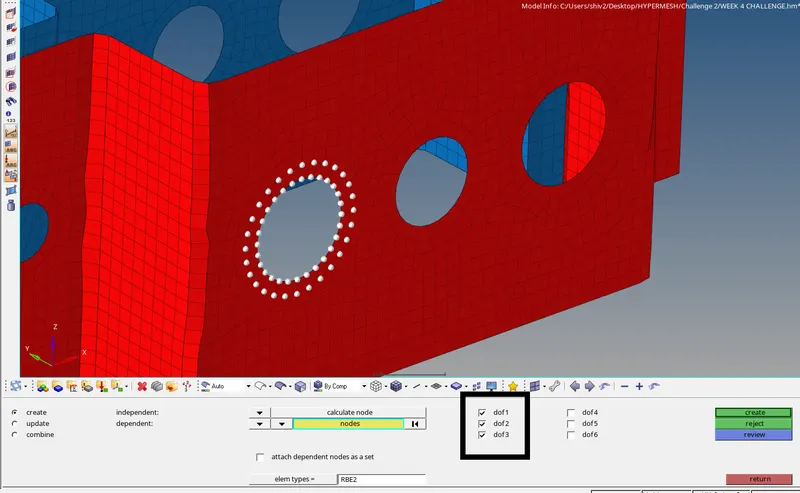
Fig: RBE2 link is created with transitional DOF constrained.
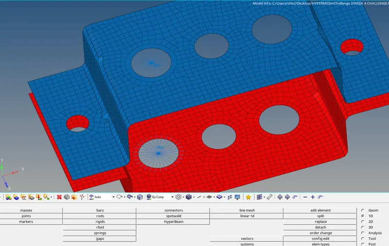
Fig: RBE2s are created to join both brackets with the ROD element.
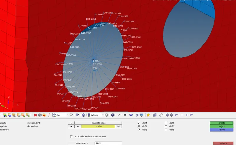
Fig: Links are reviewed for DOFs
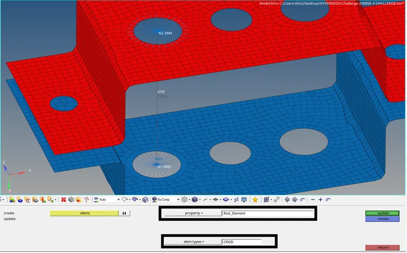
Fig: ROD element is created between two RBE2s with element type as CROD.
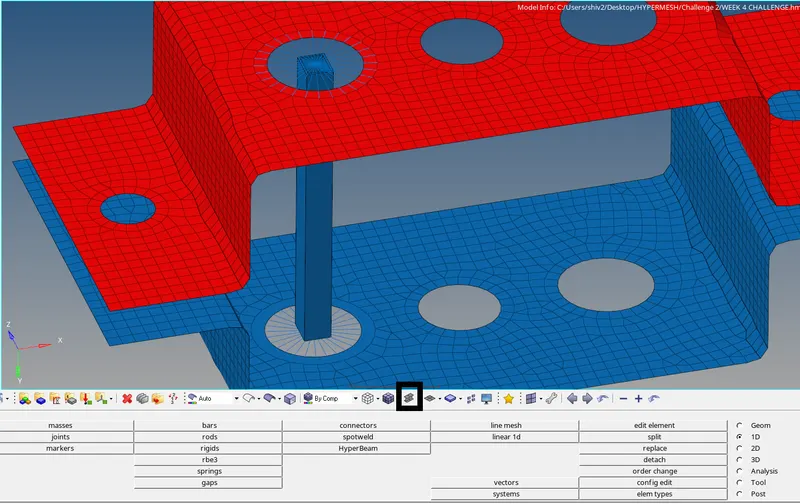
Fig: 1D detailed element representation is opted to see rod created.
Similarly, other elements are created using the same process with the required type of links and element type.
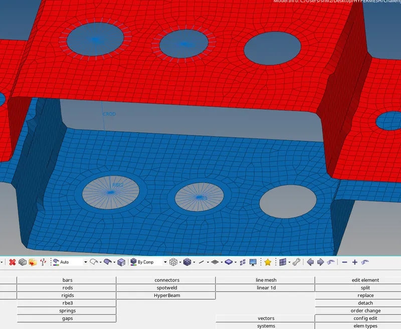
Fig: RBE3 links are generated for the Beam element.
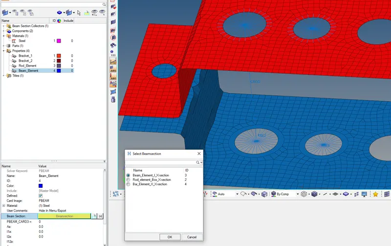
Fig: Beam element cross-section is associated with its property.
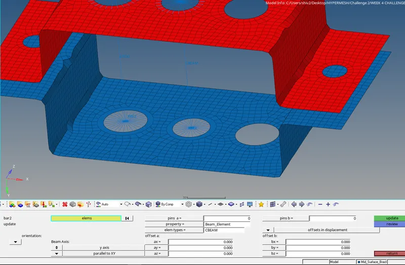
Fig: The Beam element is updated with property name Beam_Element and element type as CBEAM.
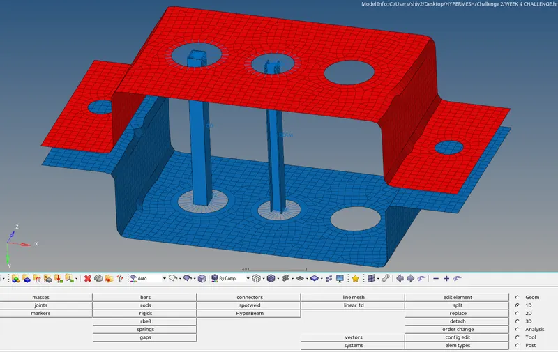
Fig: 1D detailed representation for I-section Beam.
Similar steps are used for Bar element.
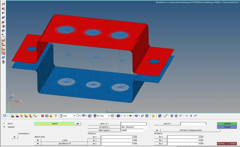
Fig: Bar element is updated with property Bar_Element and element type as CBAR.
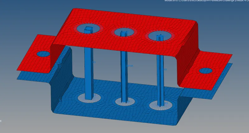
Fig: Bar detailed representation rod, beam and bar created.
Now, we need to put a mass of magnitude 10 with RBE2 links at both ends of brackets.
steps include generating RBE2 links at the end and putting a mass of magnitude 10 on the link.
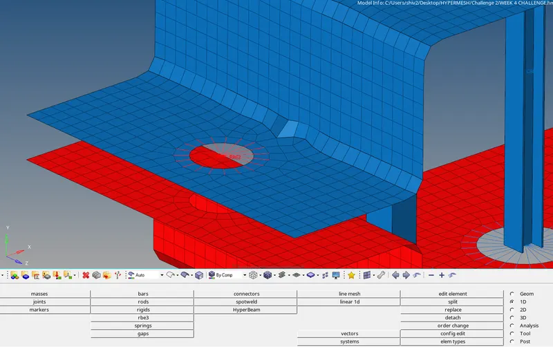
Fig: RBE2 link is created.
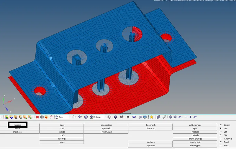
Fig: Masses option is selected under 1 D tab.
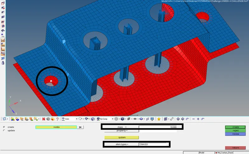
Fig: Mass of magnitude 10 is created with RBE2 link. Element type CMASS1 is selected.
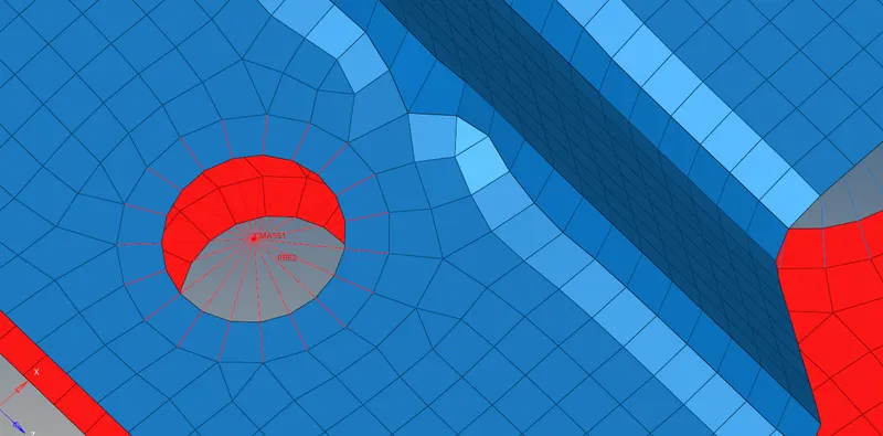
Fig: CMASS1 with RBE2 is shown.
Now, the spring element is used on the edges. Spring elements are generally named CELAS1.
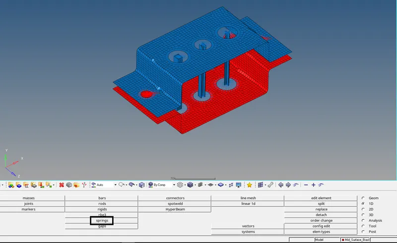
Fig: Spring element option is used under the 1D tab.
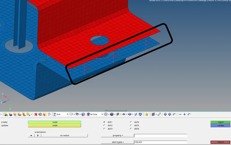
Fig: Elastic elements are created.
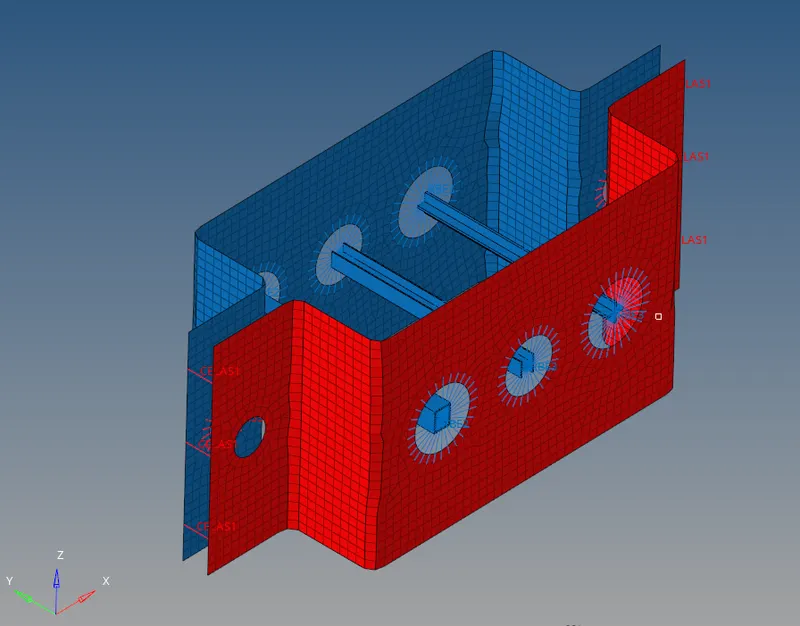
Fig: View 1
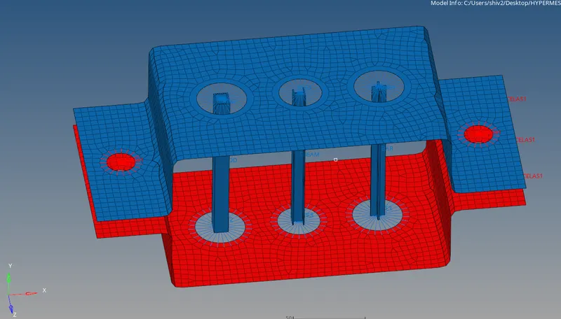
Fig: View 2
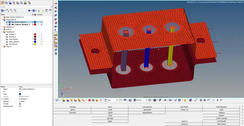
Fig: View by property
Lastly, Thickness is corrected for both mid surfaces.
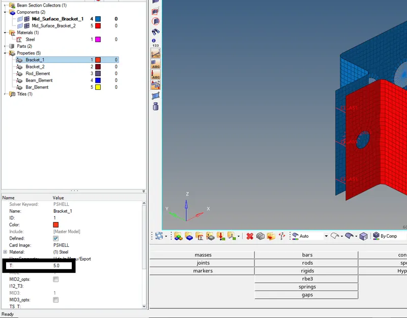
Fig: Thickness is assigned to the mid-surface as per parent geometry.
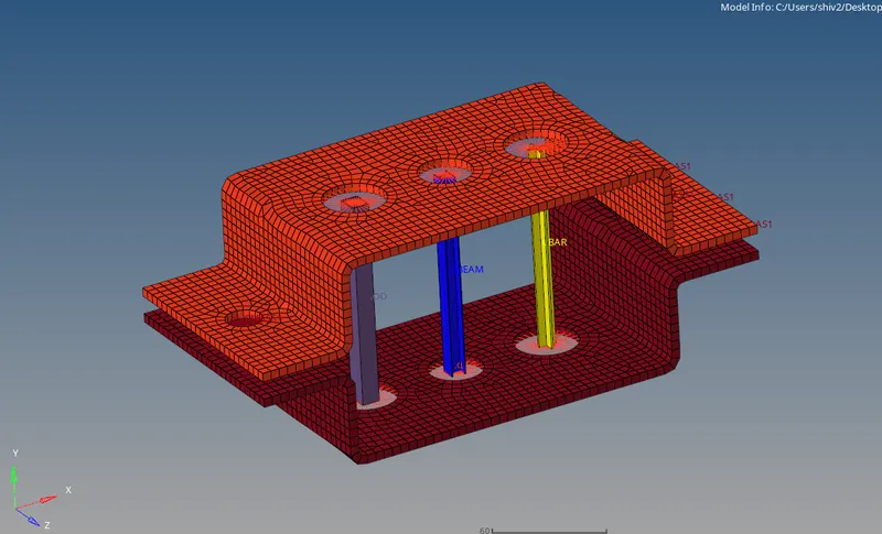
Fig: 2D and 1D Detailed element representation of the complete geometry.
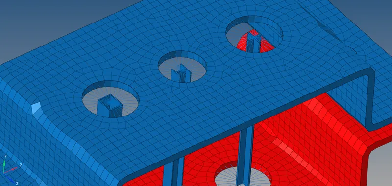
Fig: Zoomed ID element cross-sections.
CONCLUSION:
- Hyperworks suite is a focussed and detailed tool for finite element analysis.
- Common edit tools under GEOM, 1-D, 2-D and different tabs are very handy.
- Detailed cross-sections are provided under HYPER BEAM tabs.