Assembly of a Sun-seeker Predator Yacht
TITLE
Assembly of a Sunseeker Predator Yacht
OBJECTIVE
To create and assemble major parts of a yacht along with ensuring proper mates among parts and render the photorealistic images using SOLIDWORKS tool
INTRODUCTION
Sunseeker Predator Yacht
A yacht is a medium-sized sailing boat that is primarily used for cruising across small distances in the sea. A yacht is majorly a luxury utility rather workhorse, it houses various luxury facilities like a jacuzzi, open bar, luxury kitchen, heated indoor living spaces, staterooms, mini theatre, swimming pool, relaxing lounge, sunbathing lounge, etc.
It is also equipped with all major parts used in large size boats or cruisers like a double anchor for docking the boat, a radar system for communication, etc.
SOLIDWORKS TOOL
developed by DASSAULT SYSTEMES, SOLIDWORKS is a parametric modeling-based CAE package software. It has various capabilities like finite element analysis, motion analysis, multi-body dynamics, and fluid analysis. It uses various constraints to fully define the sketch along with solid body features, surface features, mates feature like perpendicularity, parallelism, and mechanical mates for assembly of parts, etc.
SOLIDWORKS also adds a rendering tool like Photoview 360 and add-ins support for standalone software like Solidworks Visualise. The major methodology starts from making solid 3d parts with help of fully defined sketches, assembling them using mates, and final rendering with appearance tools and photo view 360.
The complete process is described below
DESIGN METHODOLOGY
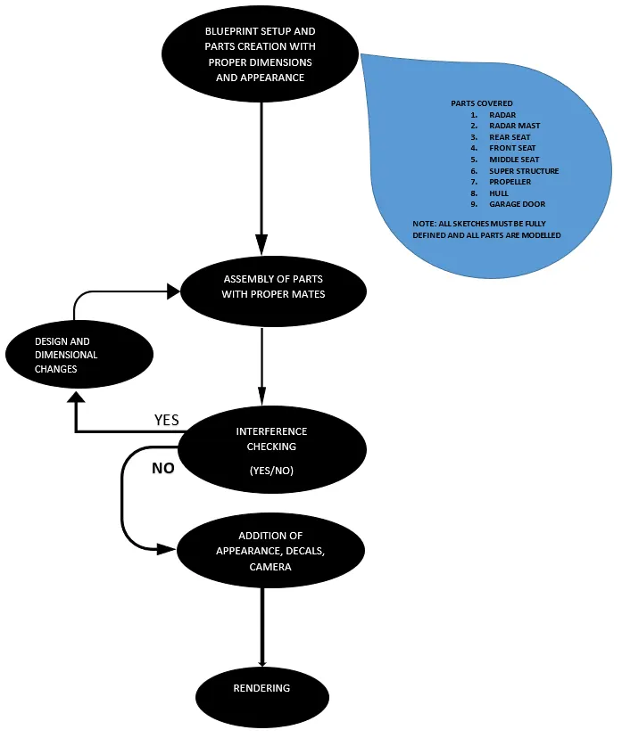
FEATURE AND TOOLS USED
- LINE TOOL
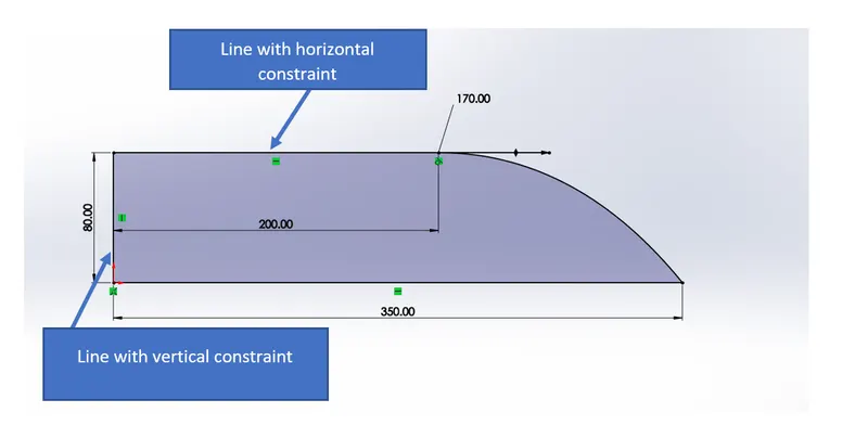
The line tool is used by defining the starting point along with dragging it to a distance to finalize the finishing point. Various constraints can be applied during the process of creating the line like a vertical, horizontal, tangent to a curve, etc. various line types can be used are midpoint lines, construction line for reference, etc.
While sketching any entity, proper dimensioning must be ensured to fully define the sketch
- SPLINE TOOL
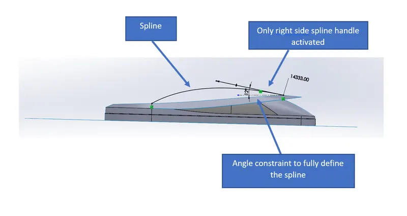
The spline is a curve type that is defined by different points with proper positioning, spline handles along with proper weight dimensions to finalize the shape. Various constraints can be applied during the process of creating the spline like angle constraints, tangent constraints, coincident, etc. to fully define the sketch. it is also feasible to activate only certain Spline handles.
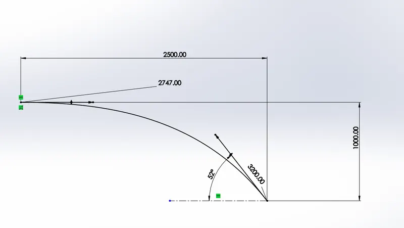
Spline example with all handles activated which are fully defined later
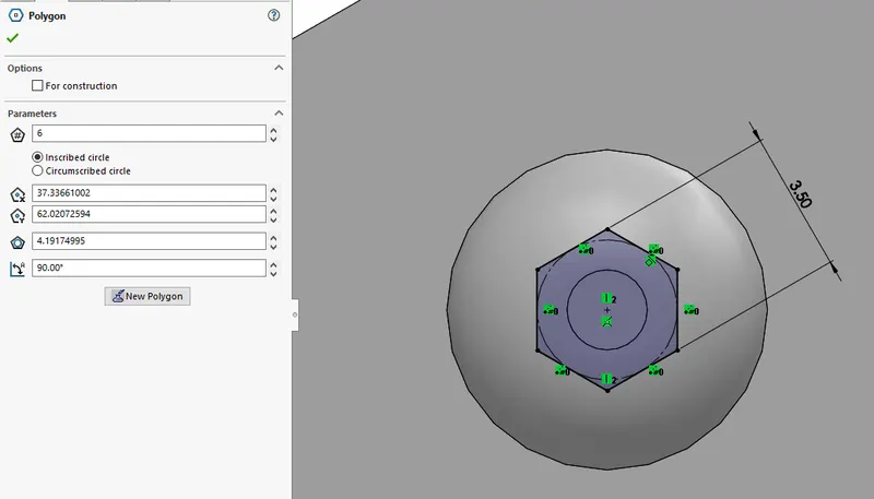
- POLYGON
It is defined by starting the center point selection along with dragging along any direction to define the final size and orientation of the polygon. the number of sides and definitions like an inscribed or circumscribed circles can also be given.
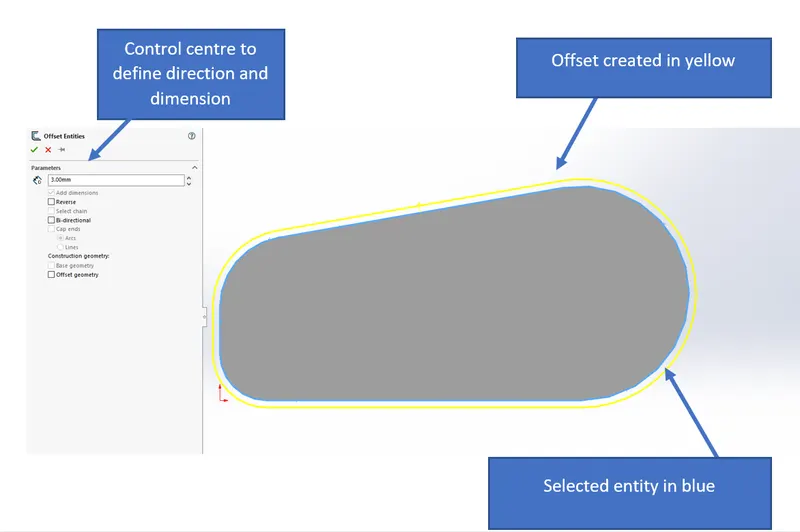
- OFFSET TOOL
The offset tool is used by selecting any predefined sketch to create its offset shape with direction control with respect to the selected sketch.
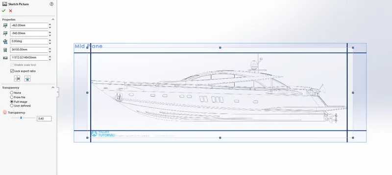
- SKETCH PICTURE TOOL
A picture with an ideation sketch is brought into the part file for geometric and dimensional reference to achieve the desired sketch. location and Transparency of imported pictures can be adjusted inside the feature options.
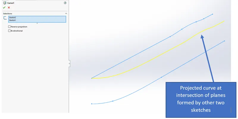
- PROJECTED CURVE TOOL
A minimum of two 2D sketches is extended as curves in lateral sides to form a projected curve at the intersection of the planes generated by sketches.
SOLID BODY FEATURES
- REVOLVE FEATURE
A close contoured 2D sketch is revolved around a particular axis to create an axisymmetric solid body feature. It can be defined bi-directionally with respect to the contoured sketch. Solidworks allows various options for revolve like angle value, offset from the surface, up to vertex, etc.
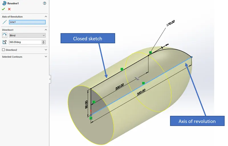
example 1
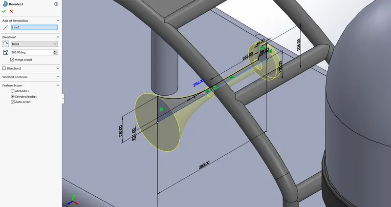
example 2
- FILLET FEATURE
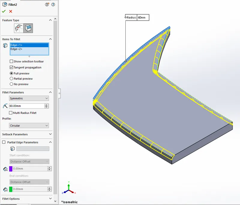
Internal or external Sharp edges on any part are rounded to improve the aesthetics and safety from sharp edges. Different types of profiles are there like circular, conic radius, etc, fillet types like face fillet, full round fillet, and radius dimensions can be symmetric or of variable size.
- EXTRUDED BOSS/BASE FEATURE
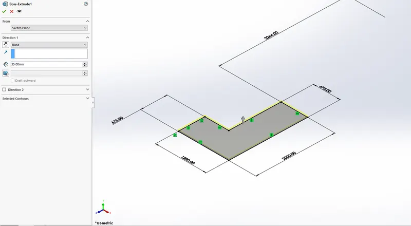
A closed 2D sketch on any plane is extruded to form a 3D solid body with bi-directional control like taking the extrusion to blind length, up to any surface, vertex, or offset from the surface, etc. to define the final output. Final dimensions are controlled with respect to different conditions like the start point (can be the sketch plane, offset plane, etc) and final point (can be a vertex, reference plane)
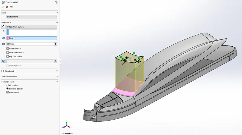
- EXTRUDED CUT FEATURE
A closed 2D sketch on any plane is extruded to form a cut through a solid body or multiple bodies with the same controls as in extrude boss/base feature to define the final output. The option of selection to keep anybody is given in the multi-body case and this feature can be controlled differently in two opposite directions with respect to sketch with options like blind length, offset from the surface, up to vertex, or surface.
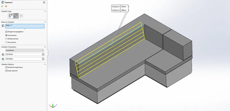
- CHAMFER
Chamfer feature is the same as that of a fillet, but the profile is that of an angled surface rather curve in the fillet. Chamfer types are further classified as angle distance, offset face, vertex, distance distance with symmetric and asymmetric dimensions options. an edge or a point can be selected for the same.
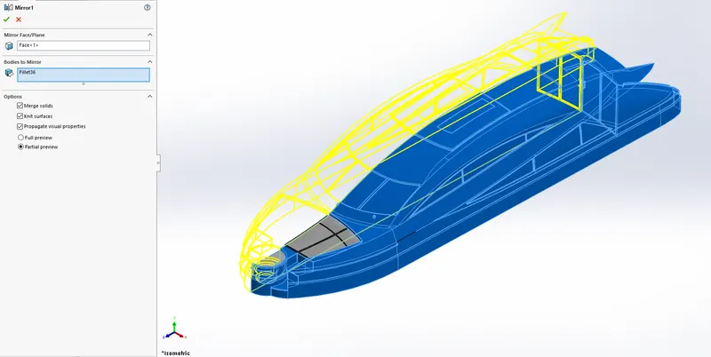
- MIRROR FEATURE
This feature is used to mirror any solid body, faces, and features about any face or plane, in this feature we also get an option to merge solids when the mirror plane intersects both the bodies
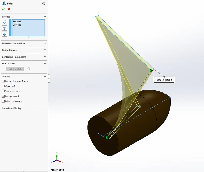
- LOFTED BOSS/BASE
A solid feature is created between a minimum of two profiles (starting and ending) with directional control parameters like centreline parameters (control sketch from midpoints of profiles) and guide curves (control sketch for boundaries of the profile)
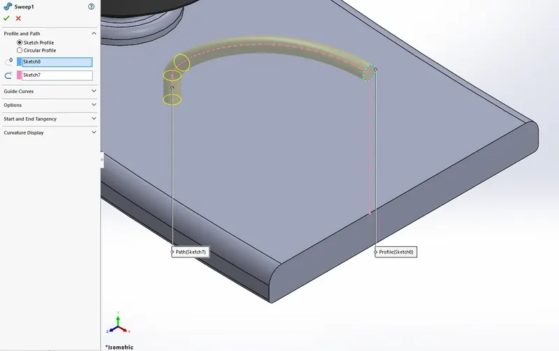
- SWEPT BOSS/BASE FEATURE
A closed 2D sketch is swept along a path that can be closed or open to form a solid body feature. It has control parameters like centreline parameters (control sketch from midpoints of the profile) and guide curves (control sketch for boundaries of the profile)
SURFACE FEATURES
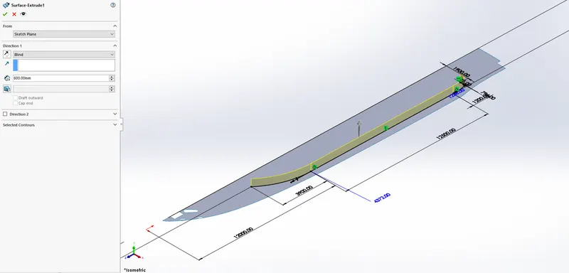
- EXTRUDED SURFACE FEATURE
A closed 2D sketch or open curve on any plane is extruded to form a surface feature with bi-directional control like taking the curve to blind length, up to any surface, vertex, or offset from the surface, etc. to define the final output. Final dimensions are controlled with respect to different conditions like the start point (can be the sketch plane, offset plane, etc) and final point (can be a vertex, reference plane)
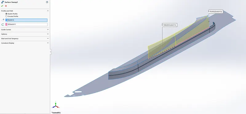
- SWEPT SURFACE FEATURE
A closed 2D sketch is swept along a path that can be closed or open to form a surface feature. It has control parameters like guide curves, profile twist, and tangency control for the start as well as the end.
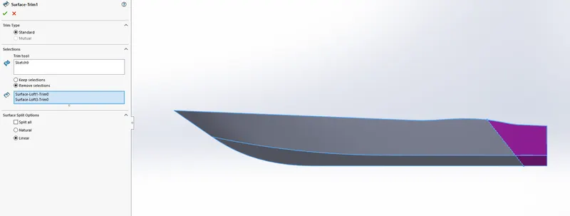
- SURFACE TRIM
Any surface can be trimmed along any direction with respect to a closed or open curve/profile, the option of which bodies to keep or trim away is also included.
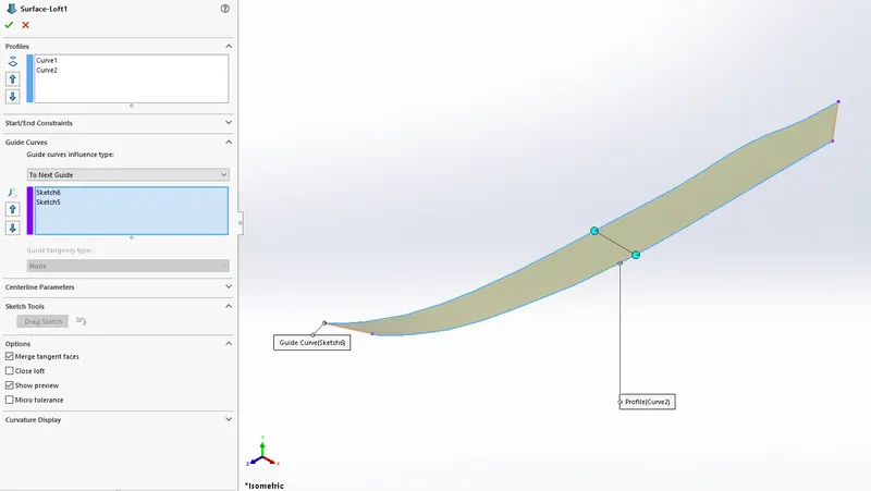
- LOFTED SURFACE
A surface feature is created between a minimum of two profiles (starting and ending) with directional control parameters like centreline parameters (control sketch from midpoints of profiles) and guide curves (control sketch for boundaries of the profile)
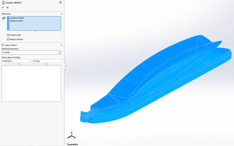
- SURFACE KNIT
It combines the different surfaces into a single surface.
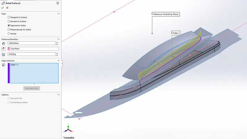
- RULED SURFACE FEATURE
A ruled surface can be formed in a specified direction from pre-defined edges to options like perpendicular to vector, tapered to vector, normal and tangent to surface options. Operations like knitting, trimming of the ruled surface can be done later.
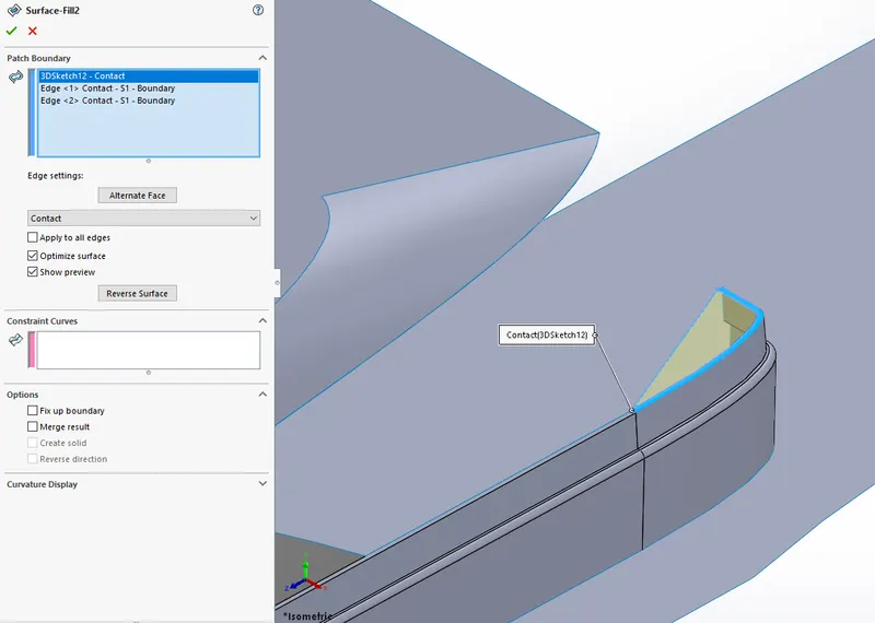
- SURFACE FILL
A surface is created to close the boundary defined by sketches, curves or edges, etc.
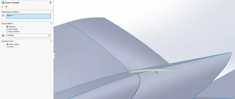
- EXTENDED SURFACE
Any edges or face on a surface is extended with control over extension type and length.
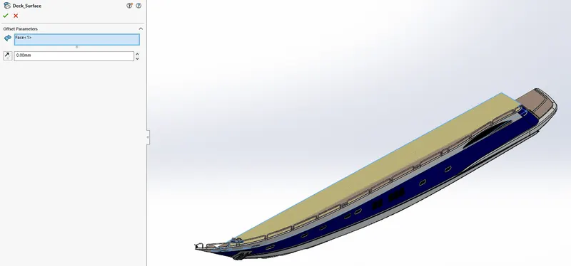
- OFFSET SURFACE
A duplicate offset surface is created with control over the direction
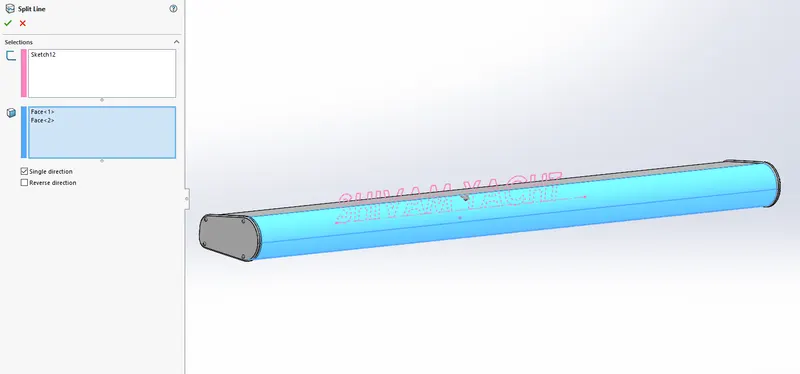
- SPLIT LINE
This feature allows us to project any sketch or text on any surface to create separate split surface parts for appearance
ASSEMBLY FEATURES
Assembly features include fixing a particular base body with assembly constraints for further completion. It includes mates like distance, coincident, parallel, concentric, etc. Some most used mates are explained below
- COINCIDENT MATE
In this mate, any two planar faces can be made coincident or can be given a distant mate.
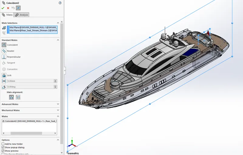
Example coincident mate between mid planes of the hull and rear seats
- CONCENTRIC MATE
This mate constraint two circular entities where the axis of the entities and curved surfaces are aligned in circularity
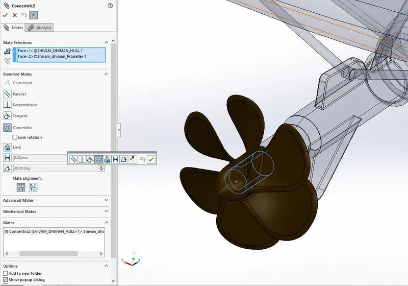
Example concentric mate between the propeller and prime mover shaft
- DISTANCE MATES
This mate is an added advantage over coincident mate, which adds a distance between the selected entities for mates
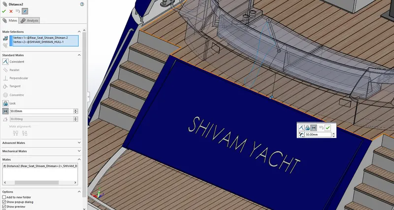
example distance mate between the rear seat and hull surface via selected entities in light blue color shown in the example
ASSEMBLY MODEL AND PART IMAGES
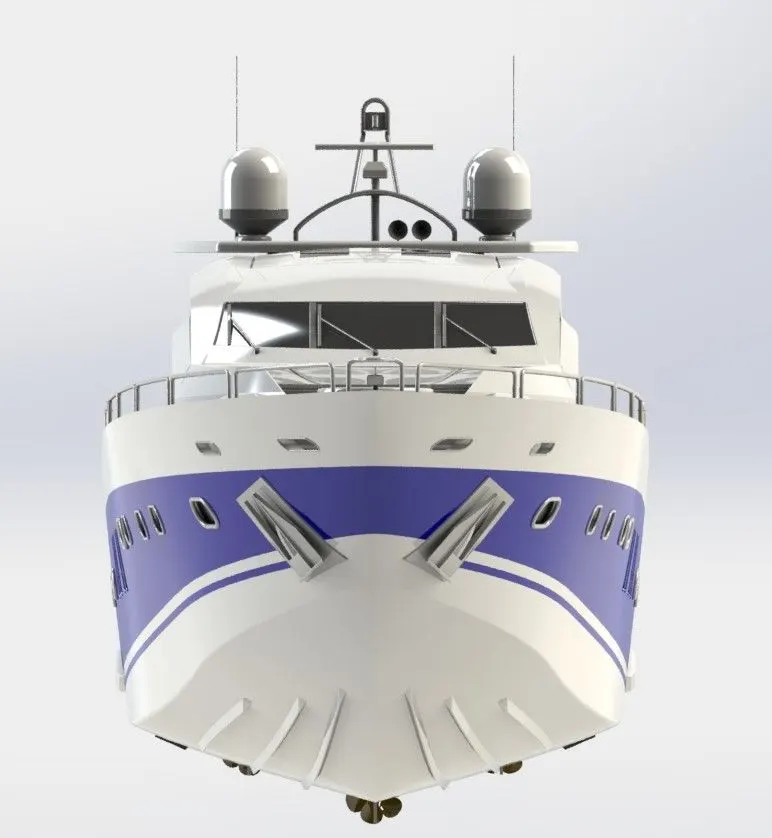
FRONT VIEW
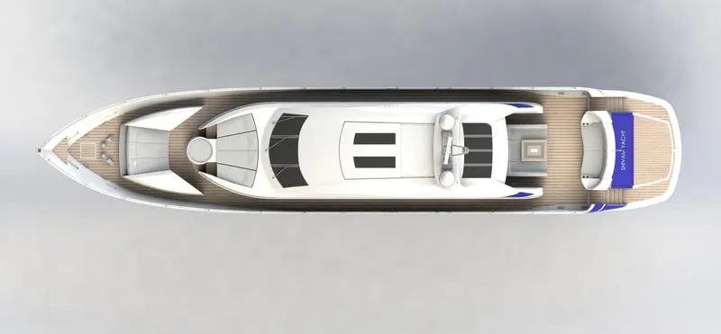
TOP VIEW
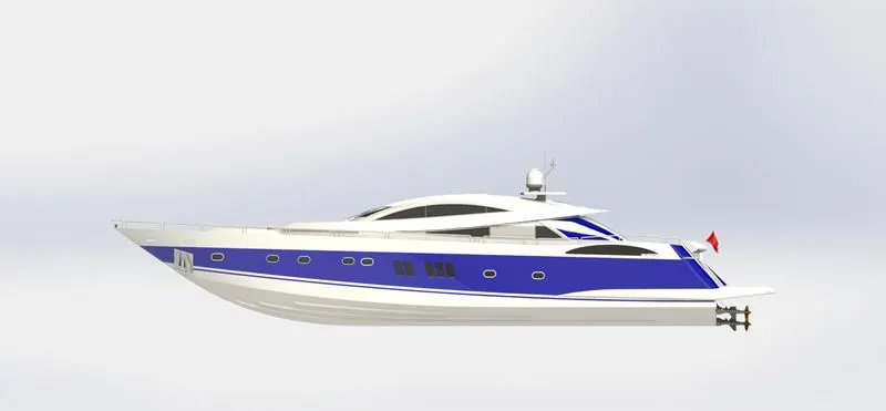
SIDE VIEW
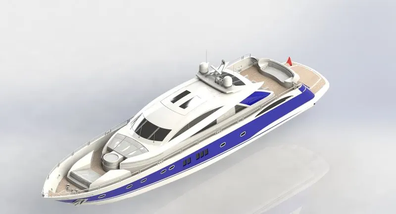
ISOMETRIC VIEW
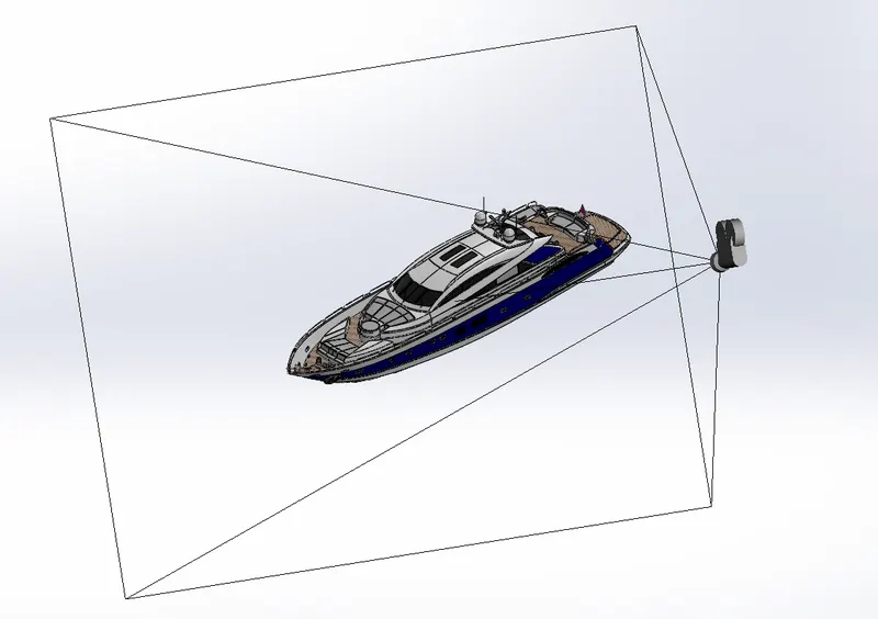
CAMERA VIEW
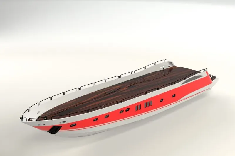
HULL
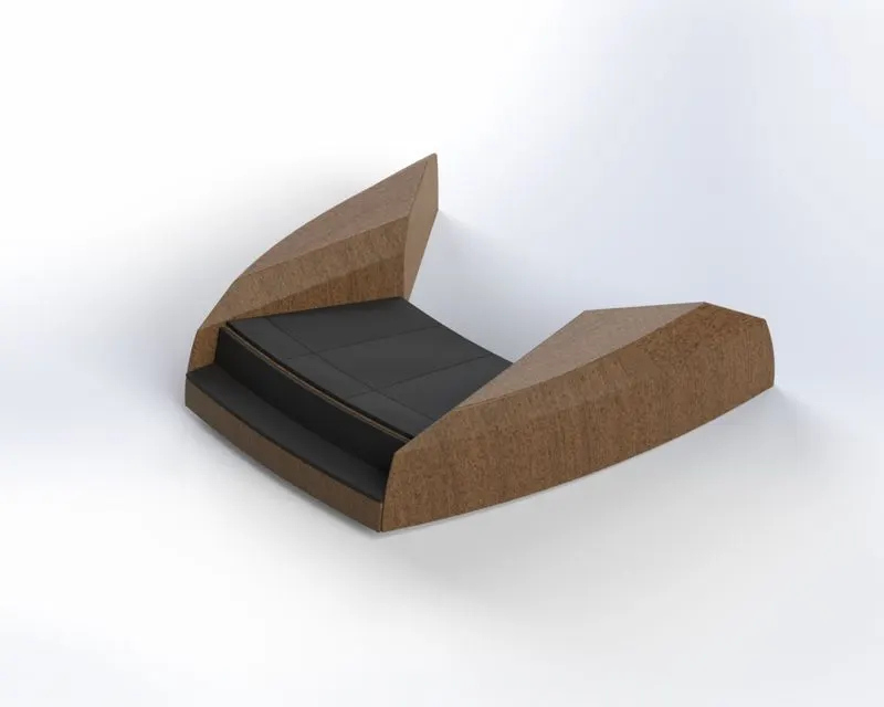
FRONT SEATS
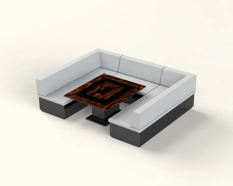
MIDDLE SEATS
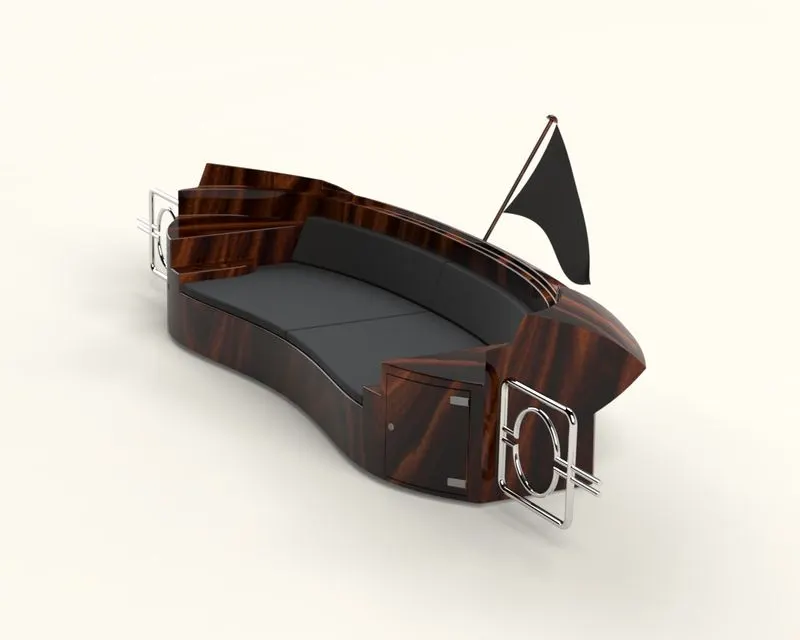
REAR SEATS
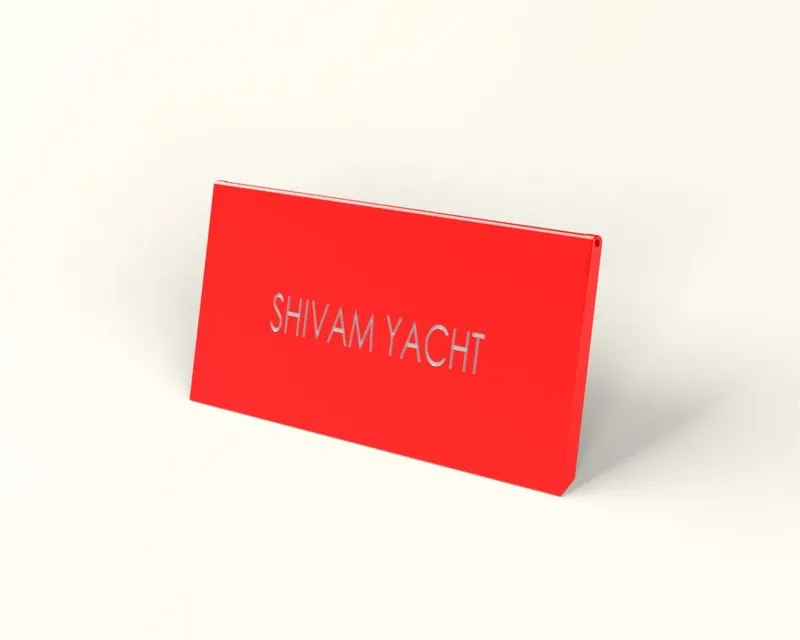
GARAGE DOOR
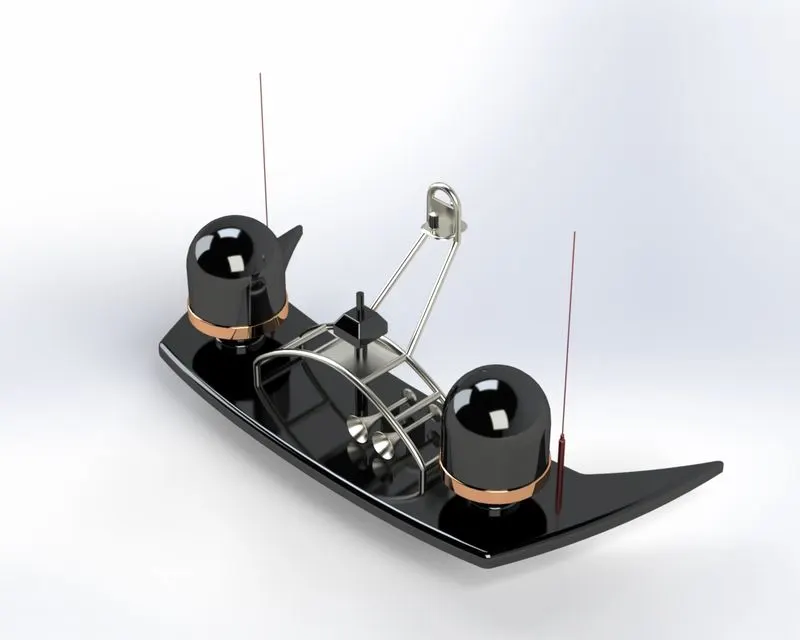
RADAR MAST
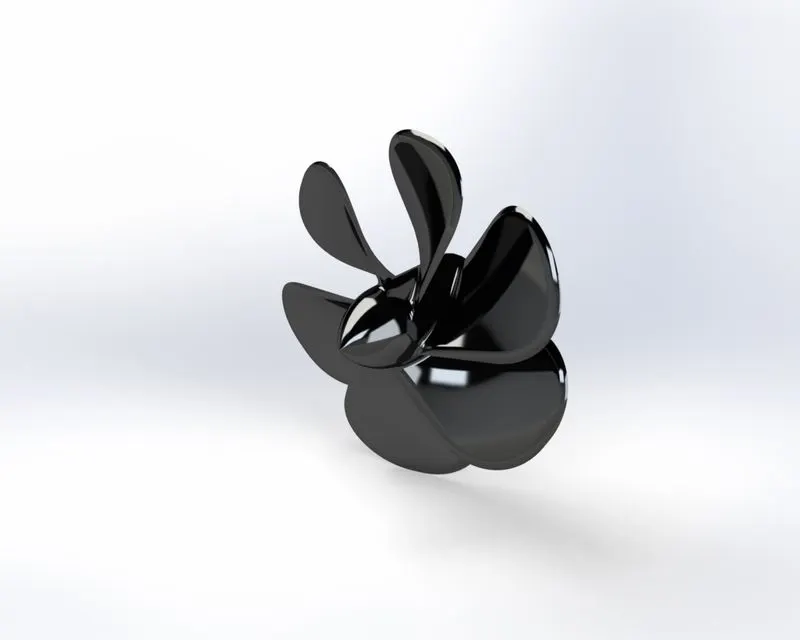
PROPELLER
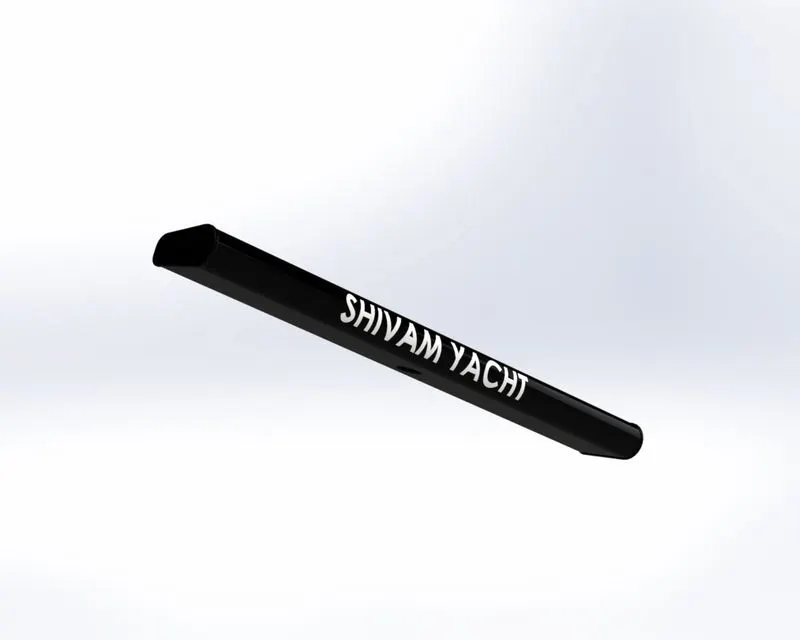
RADAR
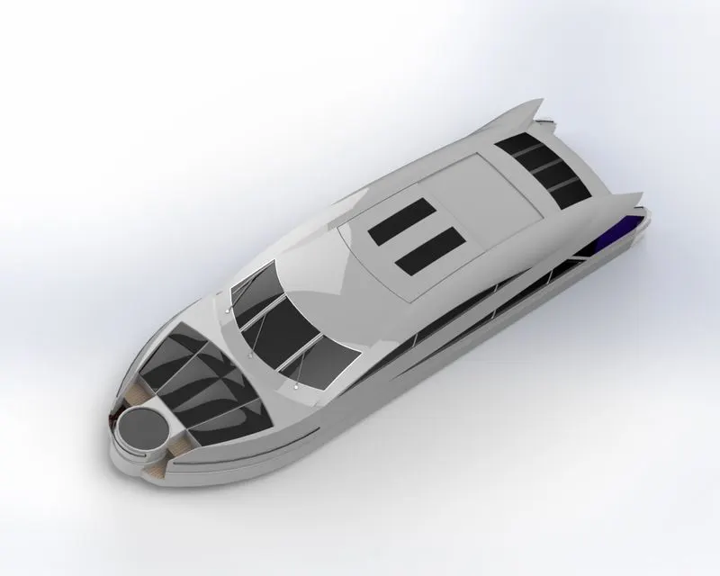
SUPERSTRUCTURE
ASSEMBLY RENDER IMAGES
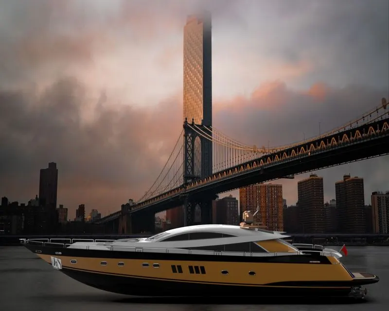
RENDER 1
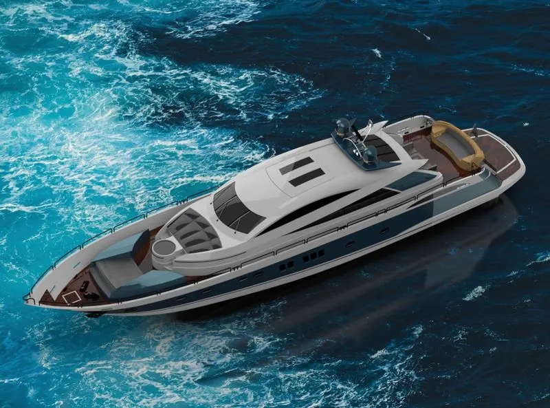
RENDER 2
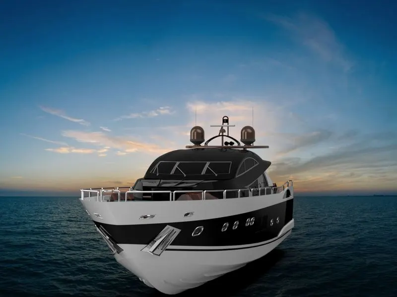
RENDER 3
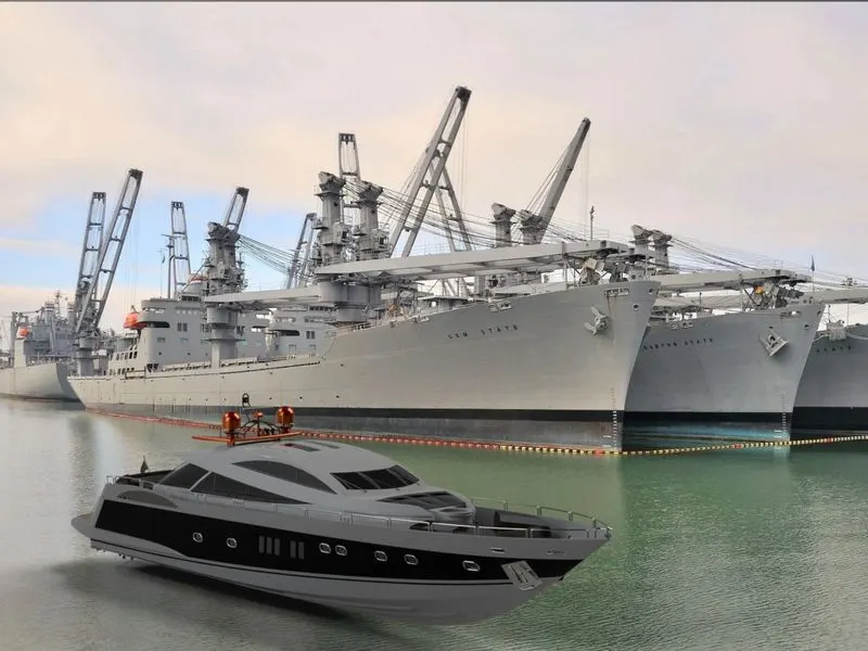
RENDER 4
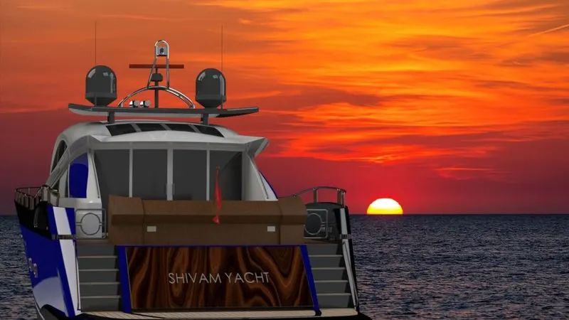
RENDER 5
CONCLUSION
- Blueprint setup helps a lot in proper dimensioning and ease of assembly
- Parts of the YACHT model are created with proper dimension, constraints, and fully defined sketches
- Proper mates are ensured while assembly with zero interference
- Each component is given proper appearance along with decals for looks and branding
- camera and lights are added for proper realistic rendering
- Solidworks visualize is used for rendering with proper material appearance and backplates
- Lastly, Solidworks is a great tool for concept ideation, parts creation, end product visualization, drawing creation for fabrication