Project 1 - 2D meshing on the instrumental Panel
AIM: To create 2D mesh on the instrument panel maintaining the quality standards alloted with proper mesh flow in order to get the best results out of solver.
METHODOLOGY:
General steps involve
Geometry clean-up >> Mid surface generation >> PID setting >> 2D Meshing
Note: Further intrications are discussed individualy while in the sub-sections.
Step 1: Geometry Clean-up
In the process of geometry clean-up unwanted faces are deleted, new faces are formed and topology is performed.
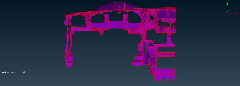
Fig: Raw Geometry
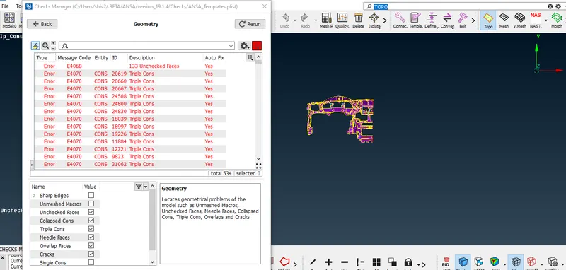
Fig: Initial Topology and geometry check is performed to get the initial problems. Later on corrective measures are performed.
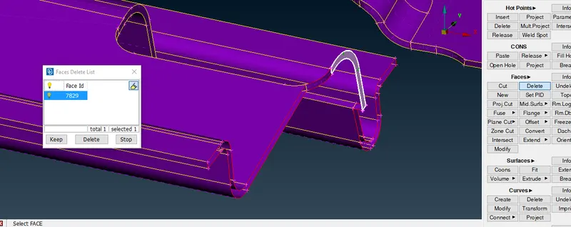
Fig: Unwanted faces are deleted
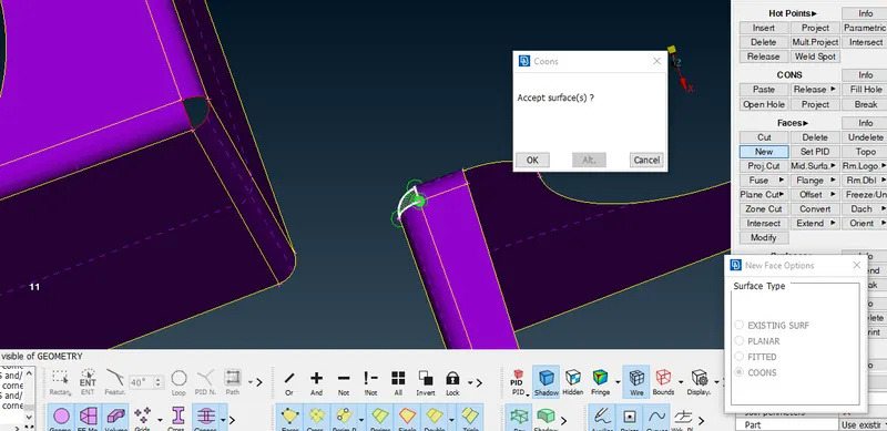
Fig: unchecked faces are formed using coons and existing surface methods. The similar steps will continue while correcting the mid-surface generated.
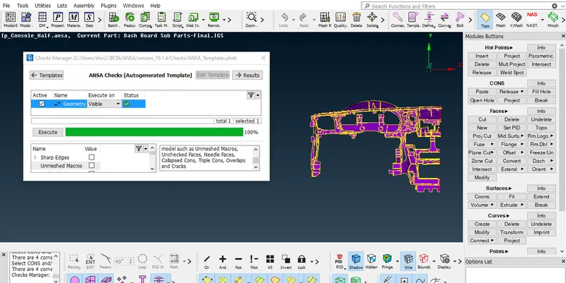
Fig: Final Geometry check
STEP 2: Mid surface generation
There are several methods of generating mid surfaces, in this case mostly offset method is used and middle surface option is used to create mid surface for th ribs.
Main steps involve:
Thickness measurement >> selection of proper method >> Topology and corrective measures
Note: PID is set with thickness allotment after the mesh generation.
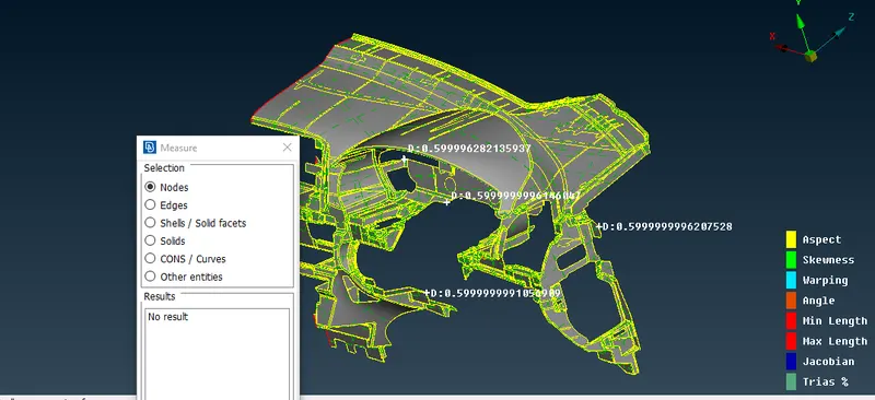
Fig: Thickness found to be .6 along majority of the features of the part given except ribs
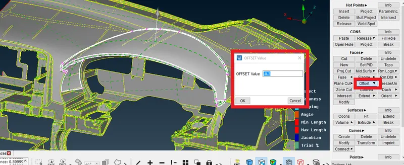
Fig: Offset given to majority of connected faces to form the mid surface.
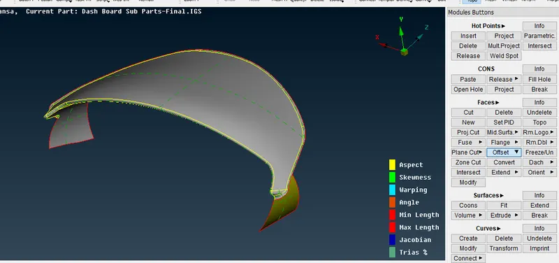
Fig: Mid surface formed
Note: Many sections with same thickness are selected collectively to form mid surace of the component in the process.
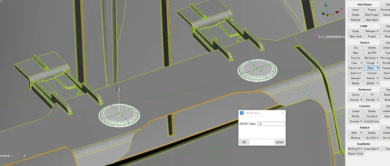 Fig: Offset is created to form mid surface of feature shown in the figure after thickness measurements.
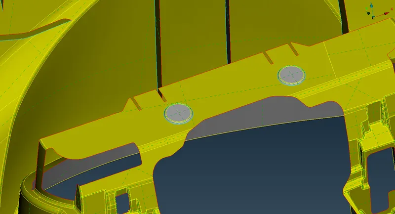
Note: Later the faces are extended and joined to obtained mid surface.
Now, Mid surface is generated for the ribs following the same procedure with different set of operations. Major steps involve
Creating mid surface using middle option >> extending the middle surfaces to rest of the mid surface to ensure proper feature capturing.
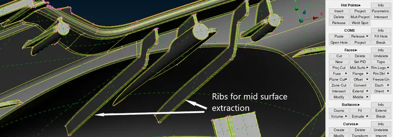
Fig: Ribs for mid surface extraction.
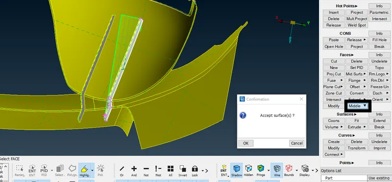
Fig: Mid surface generated using middle option.
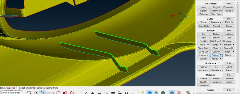
Fig: Edges of mid surface are selected for extention to the parent part for proper feature capturing
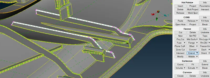
Fig: Parent body faces are selected for extention later triple cons are released to detach the mid surface from the parent body.
Same steps are performed on the the complete part to begin for mid surface generation.
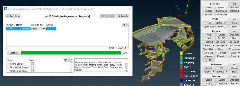
Fig: Final Geometry check after creating mid surface for the complete part.
STEP 3: Mid-surface generation.
Major steps involve
Input Mesh quality and mesh requirements>>Mesh Generation >> Smoothening/Reconstruction >> Elemental split >> Grid move methods.
Note: After mesh generation order can not be justified related to split, move options. Some off elements are kept near triple cons but surface are not deleted to drastically lower the off elementes
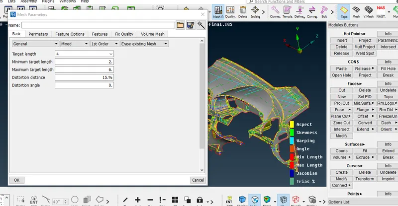
Fig: Mesh parameter are set
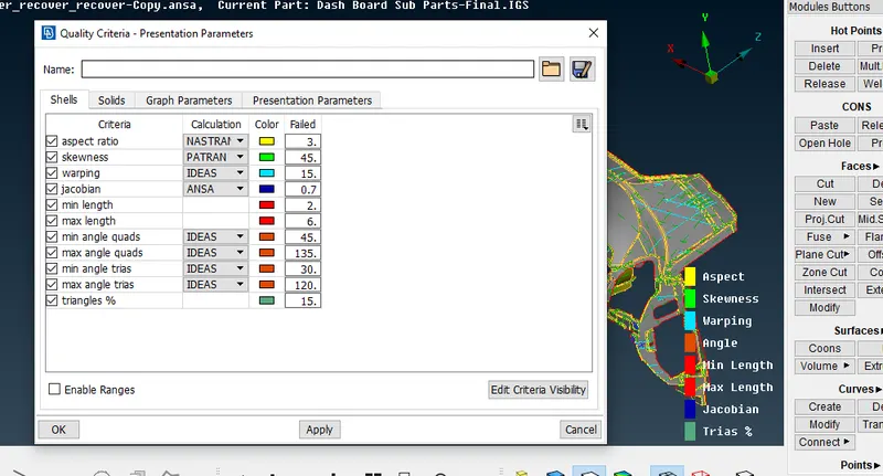
Fig: Quality Parameters are set.
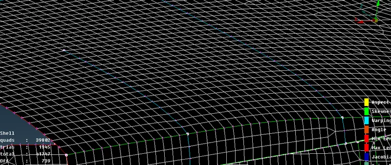
Fig: Best method is applied with reconstruction and smoothening of mesh
Number of OFF elements are also corrected by increasing of decreasing the number of parameter elements as shown in the figure below
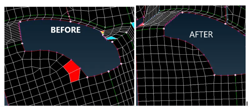
Fig: Off elements corrected by varying number of elements on parameters.
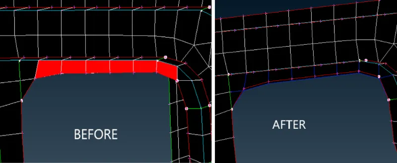
Fig: Off elements are corrected using move free option. Move free option is used where with slight movements, off elements can be corrected.
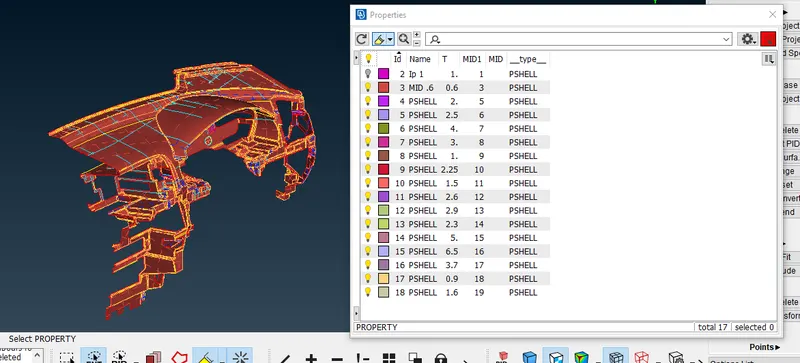
Fig: PID is set for all the different features as per the geometric data available.
Now, Transparency will be turned ON for parent geometry to check mid surface placement.
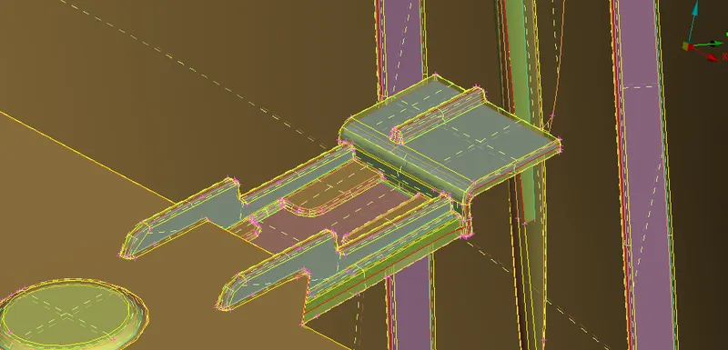
Fig: Transparency ON for parent geometry for mid surface visibility.
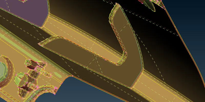
Fig: Capturing RIB features effectively
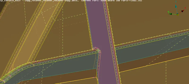
Fig: Other areas of feature capturing.
Now, Mid surface Mesh will be seen as solid shells to get gradient view for better visibility and understanding which is shown in the figures below
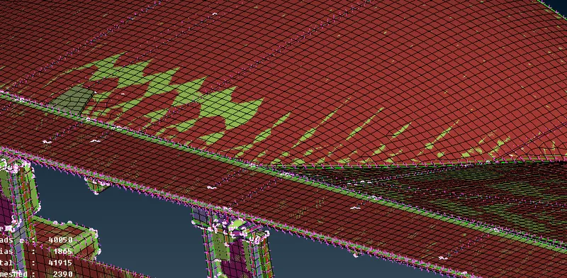
Fig: Gradient View 1
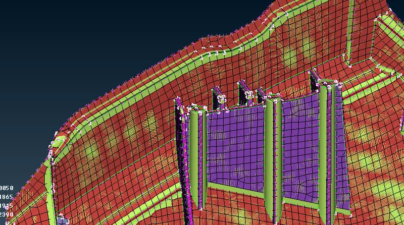
Fig: Gradient View 2
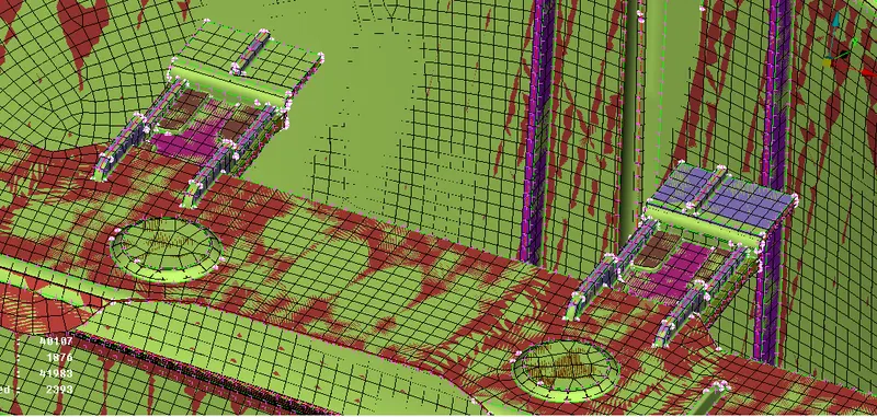
Fig: Gradient View 3
Conclusion
- ANSA is a good Pre processing tool which allows to track in between the various steps which are involved in in creating mesh generation
- This makes it an easy and powerful tool for preprocessing
- 2D meshing creates complications and difficulties while capturing circular sections and ribs of varying thickness
- It is a good practice to go through the quality parameters prior to mid surface generation which helps in creating custom cuts for fast process and efficient feature capturing
- The instrument panel part is ready for processing