Photo Realistic Rendering
TITLE
Assembly of American Chopper
OBJECTIVE:
To create major parts of the chopper motorcycle, make the assembly with proper mates among parts and render the photorealistic images using SOLIDWORKS
INTRODUCTION
American Chopper
A chopper is a two-wheeler automobile that is majorly used for cruising purposes. Major parts of a chopper include chassis, engine, gas tank, oil tank, transmission belt, chain drive, wheels, fenders, fork, seat, pedals, and more. They are majorly characterized by low ground clearance, long wheelbase, customizations, high rake angle, etc.
Solidworks Tool
It is a parametric modeling-based CAD/CAE software developed by DASSAULT SYSTEMES. It has various capabilities like finite element analysis, multi-body dynamics, motion analysis, and fluid analysis. It uses various constraints to fully define the sketch along with solid body features, surface features, mates feature like perpendicularity, parallelism, and mechanical mates for assembly of parts, etc. it also adds a rendering tool like Photoview 360 and add-ins support for standalone software like Solidworks Visualise. The major methodology starts from making solid 3d parts with help of fully defined sketches, assembling them using mates, and final rendering with appearance tools and photo view 360.
steps used in this project are described below
DESIGN METHODOLOGY
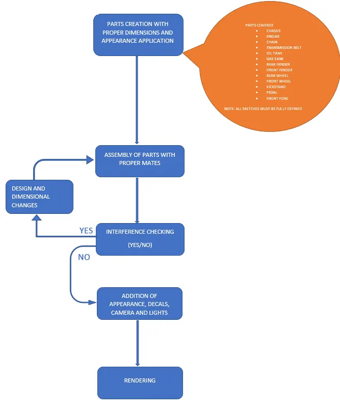
In the complete process as parts need to be designed and assembled into the final and complete chopper.
Tools and features are explained below starting from important sketch tools, solid body features, surface features, assembly features, decals and render features
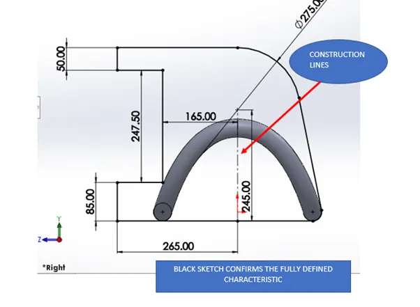
While sketching all sketches are fully defined with proper dimensions and constraints to drive any changes in the sketch. Fully defined sketches are characterized by black color and fixed position with respect to fixed references
IMPORTANT SKETCH TOOLS USED
- Line Tool
The line is defined by a starting point and dragging along a distance to finalize the finishing point. Solidworks allows features like midpoint lines and construction line which works mainly as reference lines.
- Splines
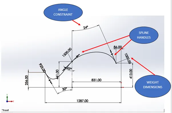
It is a type of curve that is regulated by different points and spline handles along the points. Spline handles are given weight dimensions, angle constraints, tangent constraints to define the final shape. Spline handles are activated to define.
- Offset
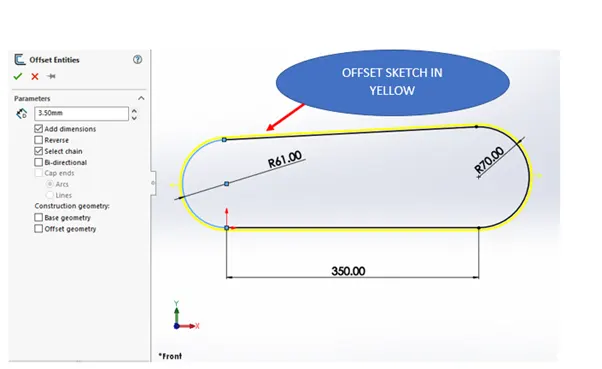
An offset is created with respect to any selected sketch with a reverse direction option and spacing dimension.
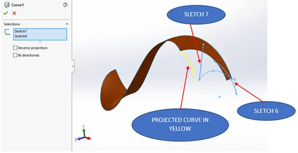
- Project curve
A curve is generated by the intersection of planes generated by selected curves or sketches.
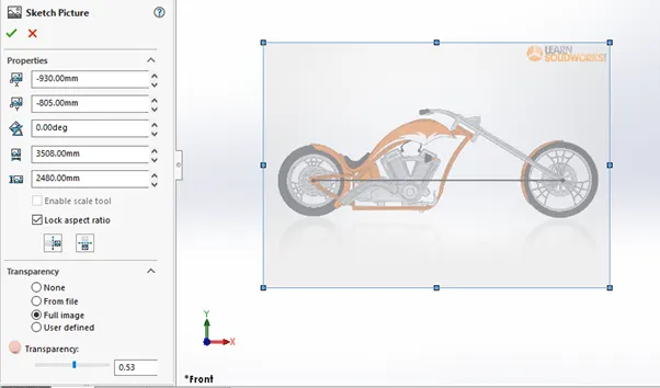
- Sketch Picture
An ideation sketch picture is imported for dimensional and geometric reference to make a sketch for the desired outcome. Transparency of pictures and location can be manipulated inside the feature.
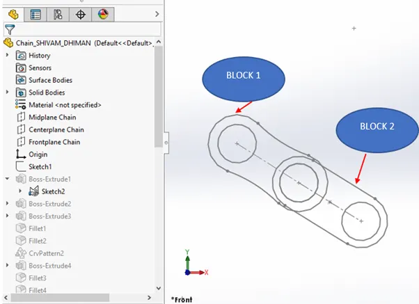
- Block
Certain closed profiles can be converted in to sketch block for easy access in the sketches. This feature is mainly used where the repetition of sketches is required with individual entity control as compared to patterning where individual entity control is not present. Blocks have a specific file type as SLDBLK file. In this project, block files are used for making chain.
SOLID BODY FEATURES
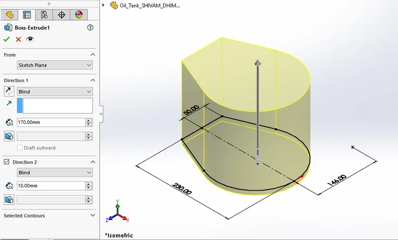
- Extruded Boss/Base
A closed 2D sketch on any plane is extruded to form a 3D solid body with bi-directional control like taking the extrusion to blind length, up to any surface, vertex, or offset from the surface, etc. to define the final output. Final dimensions are controlled with respect to different conditions like the start point (can be the sketch plane, offset plane, etc) and final point (can be a vertex, reference plane)Parts designed under this feature: Oil Tank, Front-fork, Engine, Chassis, pedal, etc.
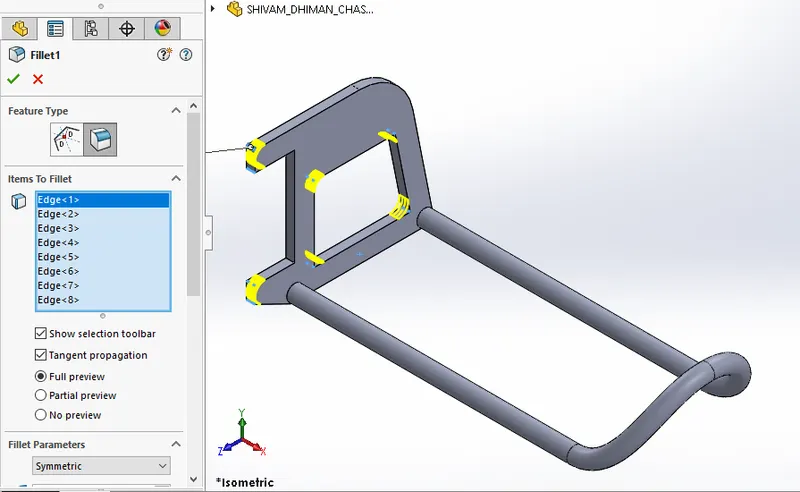
- Fillet
Internal or external Sharp edges on any part are rounded to improve the aesthetics and safety from sharp edges. Different types of profiles are there like circular, conic radius, etc, fillet types like face fillet, full round fillet, and radius dimensions can be symmetric or of variable size.Parts designed under this feature: Oil Tank, engine base, chassis, front fork, rear & front wheels, etc.
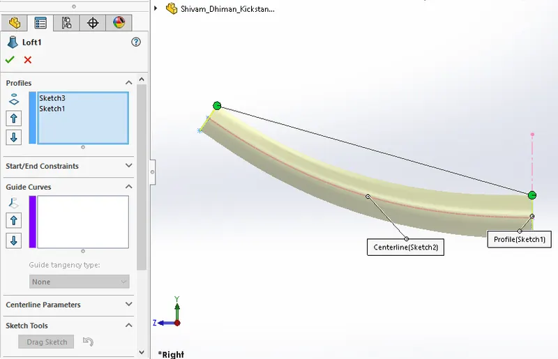
- Lofted Boss/base
A solid feature is created between minimum two profiles (starting and ending) with directional control parameters like centreline parameters (control sketch from midpoints of profiles) and guide curves (control sketch for boundaries of the profile)
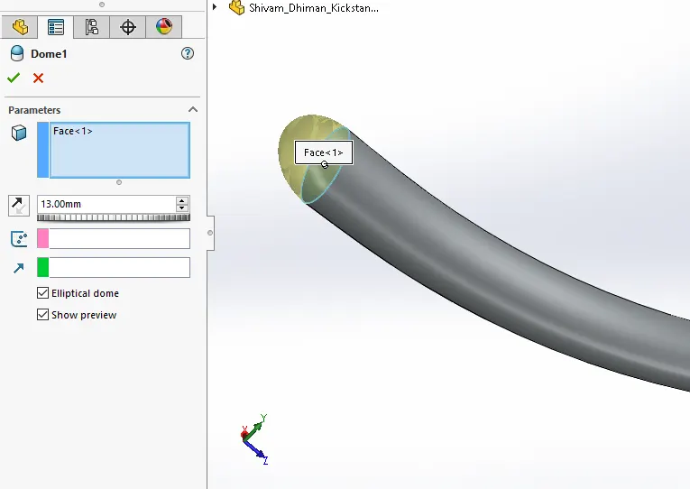
- Dome
A dome-like Solid-body can be created on a closed circular or elliptical face with a radius as a controlling dimension and an elliptical dome as an option. Parts, where this feature is used, are Kickstand, Chassis, Pedal, Front Fork, etc.
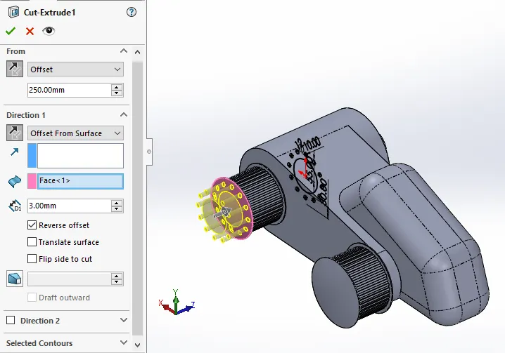
- Extruded Cut
A closed 2D sketch on any plane is extruded to form a cut through a solid body or multiple bodies with the same controls as in extrude boss/base feature to define the final output. The option of selection to keep anybody is given in the multi-body case and this feature can be controlled differently in two opposite directions with respect to sketch with options like blind length, offset from the surface, up to vertex, or surface parts designed under this feature: engine shafts, wheel treads in both wheels, headlight grooves in front fort, etc.
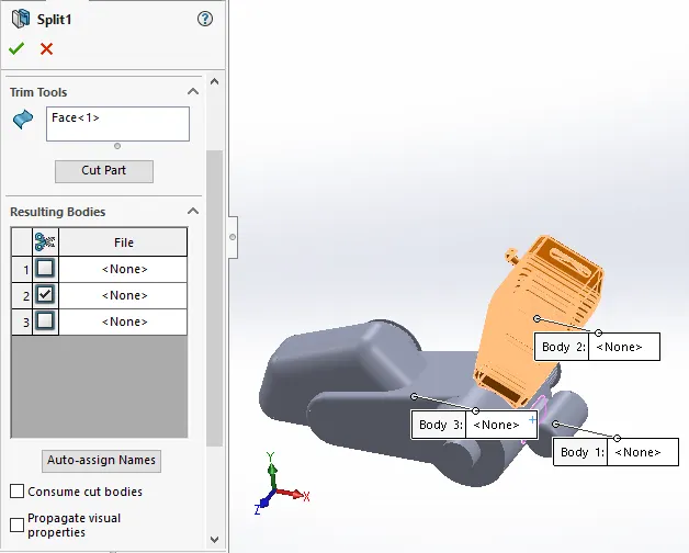
- Split
The split command is used to form multiple bodies out of a single body with respect to a trim surface (can be closed sketch or unclosed) after forming bodies it allows us to consume any resulting body out of different bodies obtained. Parts designed under this feature: engine cylinder heads, chassis parts, front & rear fenders, etc.
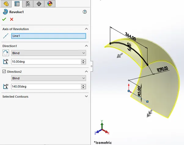
- Revolved Boss/Base
A closed 2D sketch on any plane is revolved around a particular axis to create an axisymmetric solid body. Revolve feature can be controlled differently in two opposite directions with respect to sketch with options like blind angle, offset from the surface, up to vertex or surface, etc. Parts designed under this feature: Front & rear fenders, wheels, front forks, etc
- Shell
Any solid body is converted into a hollow body with controlled uniform as well as variable size thin walls. Any face can be deleted optionally for a clear hollow view inside.
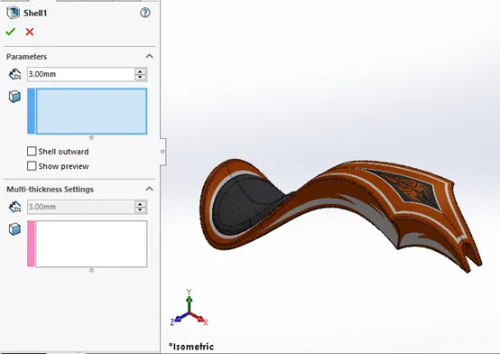
Shell feature
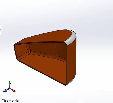
Example of the result after using shell command in the Oil tank to make it hollow for oil storage
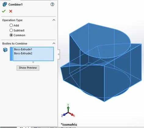
- Combine
This feature combines different solid bodies together to create a single body and options like addition, subtraction, common body selection is also available
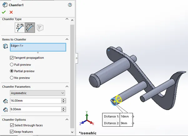
- Chamfer
The purpose of the chamfer is the same as that of a fillet, but the profile is that of an angled surface rather curve in the fillet. Chamfer types are further classified as angle distance, offset face, vertex, distance distance with symmetric and asymmetric dimensions options.
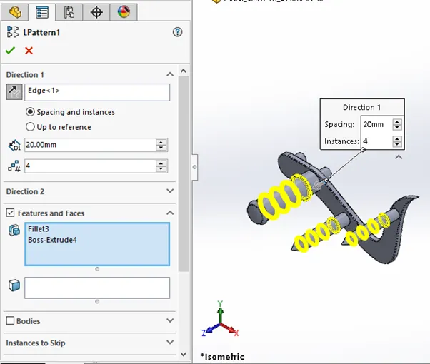
- Linear Pattern
This feature is used to repeat multiple similar features or body along any linear direction with control over spacing between features, number of entities. The feature can also be controlled in two opposite directions with respect to feature location. Parts designed under this feature: Pedal, engine, etc.
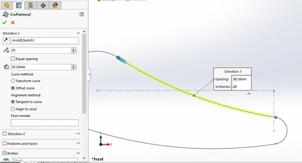
- Curve driven pattern
This feature is used to repeat multiple similar features or body along any curve with control over spacing between features, number of entities. The feature can also be controlled in two opposite directions with respect to feature location.
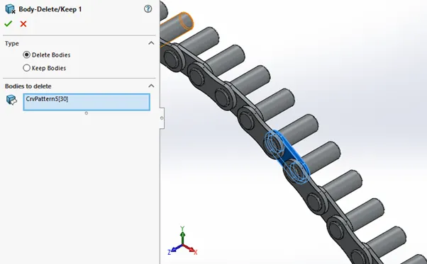
- Delete/Keep body
This feature gives us the option to delete or keep any body for further reference in the part, this feature is mostly used while multi-body patterning or configurations.
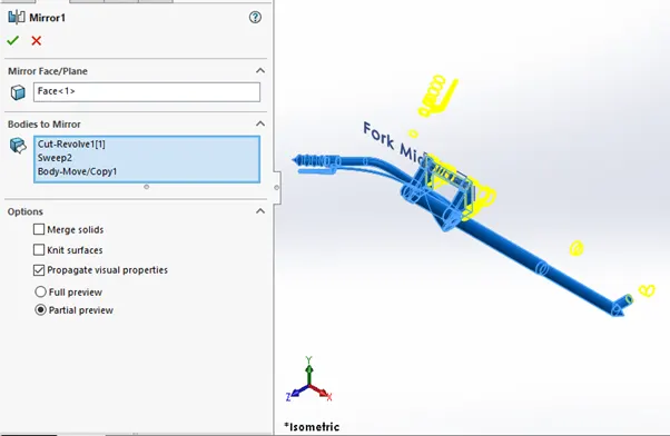
- Mirror
This feature is used to mirror any solid body, faces, and features about any face or plane, in this feature we also get an option to merge solids when the mirror plane intersects both the bodies.
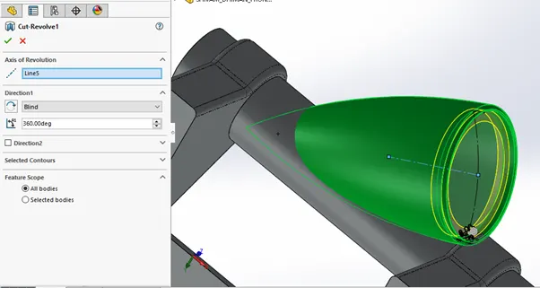
- Revolved Cut
A closed 2D sketch on any plane is revolved around a particular axis to create an axisymmetric cut part in a solid body. Revolved cut feature can be controlled differently in two opposite directions with respect to sketch with options like blind angle, offset from the surface, up to vertex or surface, etc and we can opt for which bodies to keep or cut away in case of multi-body parts.
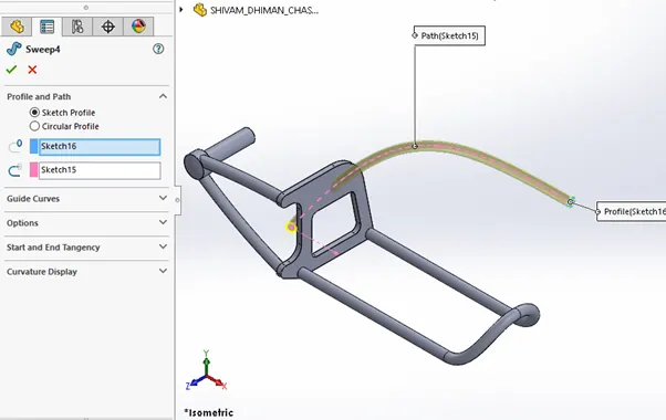
- Swept Boss/Base
A closed 2D sketch is swept along a path that can be closed or open to form a solid body feature. It has control parameters like centreline parameters (control sketch from midpoints of the profile) and guide curves (control sketch for boundaries of the profile)
- Swept Cut
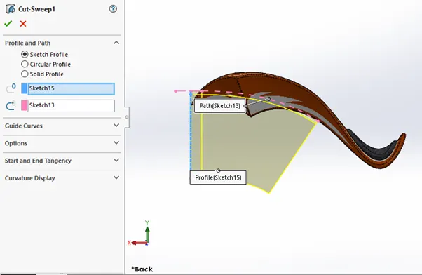
A closed 2D sketch is swept along a path that can be closed or open to form a cut feature. It has control parameters like guide curves, profile twist, and tangency control for the start as well as the end. Options to keep or swept away bodies in case of multibody is available.
SURFACE FEATURES
- Swept Surface
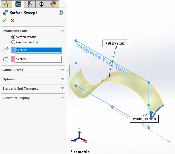
A closed 2D sketch is swept along a path that can be closed or open to form a surface feature. It has control parameters like guide curves, profile twist, and tangency control for the start as well as the end.
- Surface Trim
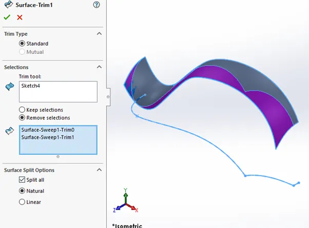
Any surface can be trimmed along any direction with respect to a closed or open curve/profile, the option of which bodies to keep or trim away is also included.
- Lofted surface
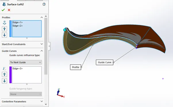
A surface feature is created between minimum of two profiles (starting and ending) with directional control parameters like centreline parameters (control sketch from midpoints of profiles) and guide curves (control sketch for boundaries of the profile)
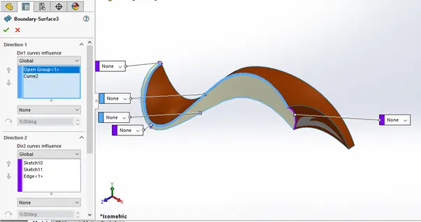
- Boundary Surface
A surface feature is created along profiles that must be tangent and continuously aligned to form boundaries of a required surface. Bidirectional control is provided to finalize output.
- Extruded surface
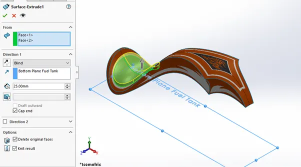
A closed 2D sketch or open curve on any plane is extruded to form a surface feature with bi-directional control like taking the curve to blind length, up to any surface, vertex, or offset from the surface, etc. to define the final output. Final dimensions are controlled with respect to different conditions like the start point (can be the sketch plane, offset plane, etc) and final point (can be a vertex, reference plane)
- Surface Knit
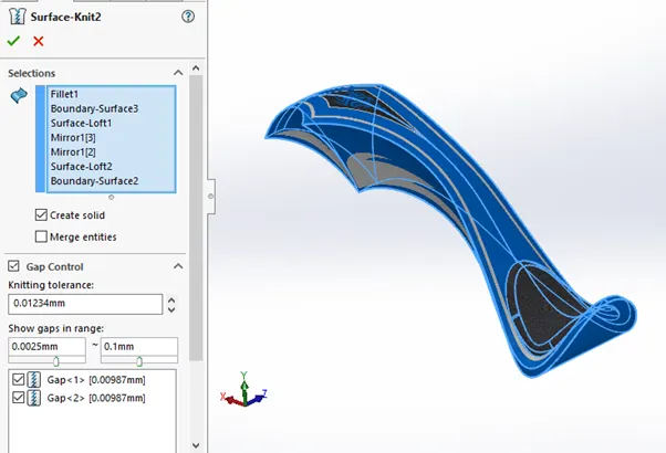
It combines the different surfaces into a single surface
ASSEMBLY FEATURES
Assembly features include fixing a particular base body with assembly constraints for further completion. It includes mates like distance, coincident, limit angle, parallel, concentric, width mates, etc. Some most used mates are explained below
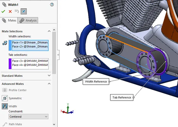
- Width
It constraints a body between two planes or plans of a body, in the example below transmission belt is constrained between planes of transmission shafts in the engine
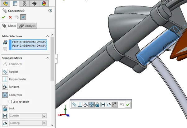
- Concentric
This mate constraints two circular entities where the axis of the entities and curved surfaces are aligned in circularity, in the example below, the front fork and chassis part is constrained under concentric mate to give turning radius to the chopper motorcycle
- Coincident
In this mate, any two planar faces can be made coincident or can be given a distant mate.
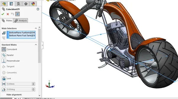
Any planes can also be constrained parallel or perpendicular in the mates
Some common features are also there which are helpful in parts creation as well as assembly like convert entities, reference geometry like planes, axis, etc
SOME APPEARANCE AND RENDERING FEATURES
- Photoview 360
This is a Solidworks add-in to edit scenes, decals, appearance at part, component as well as assembly level. It basically deals with rendering. Appearance can be added to the complete body as well as individual faces of the part like for fuel tank, separate appearance is given to seat surface. Decals details are also shown below.
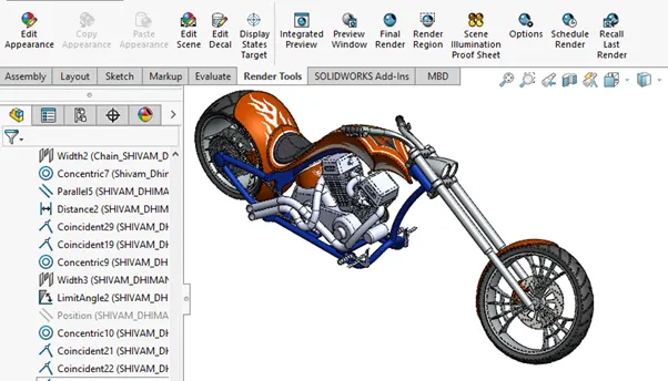
Photoview Tab with edit scene, decals, preview, final render, etc
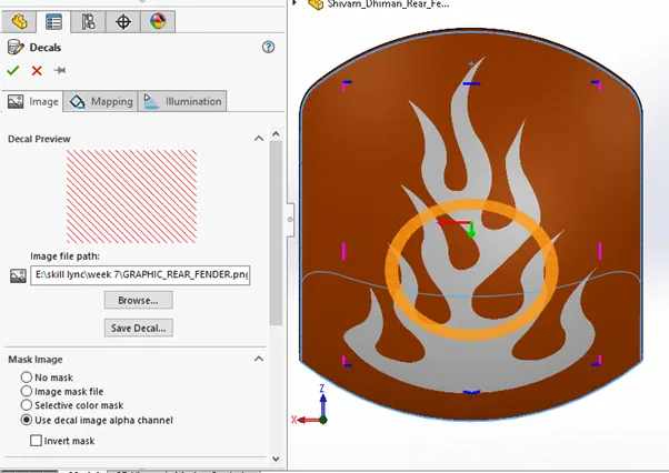
Decals can be added to any part with mapping options like projection, cylindrical, spherical, or label and illumination settings to adjust light intensity and other details
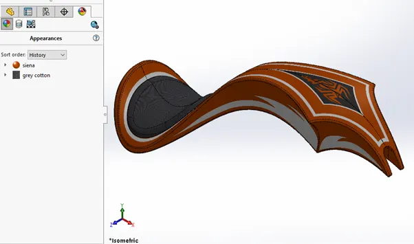
A separate appearance is given for the gas tank that is grey cotton for seat projections and automotive Siena for gas tank body
- Solidworks Visualise
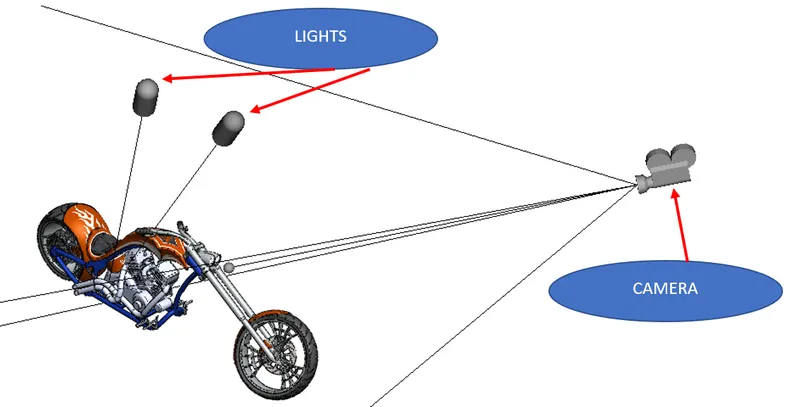
It is a stand-alone software for additional options for renderings like environment edit, extra materials for appearance, lights, backplate, etc
- We can add the camera as well as lights with options like camera position, perspective, depth of field, light intensity, etc to adjust the final render
ASSEMBLY VIEWS
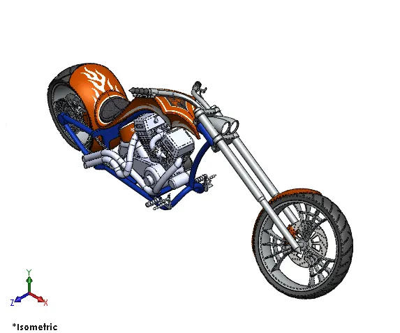
ISIOMETRIC VIEW
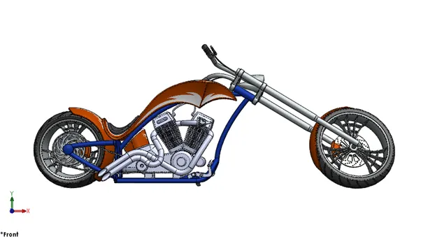
FRONT VIEW
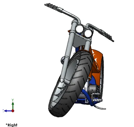
RHS VIEW
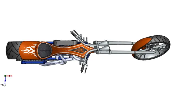
TOP VIEW
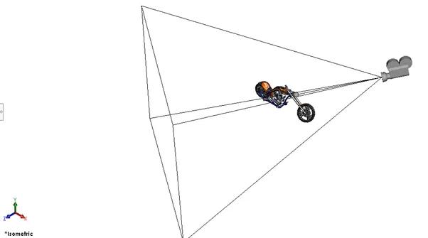
CAMERA SET UP
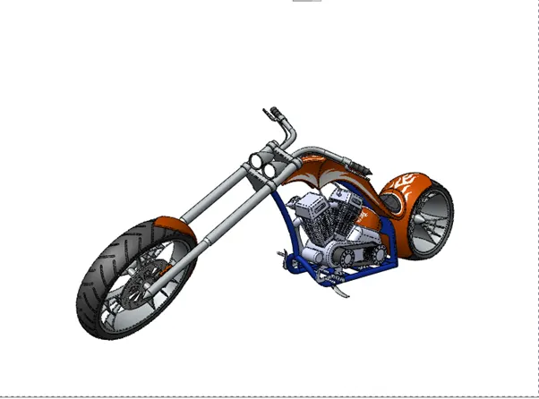
CAMERA VIEW
PART IMAGES
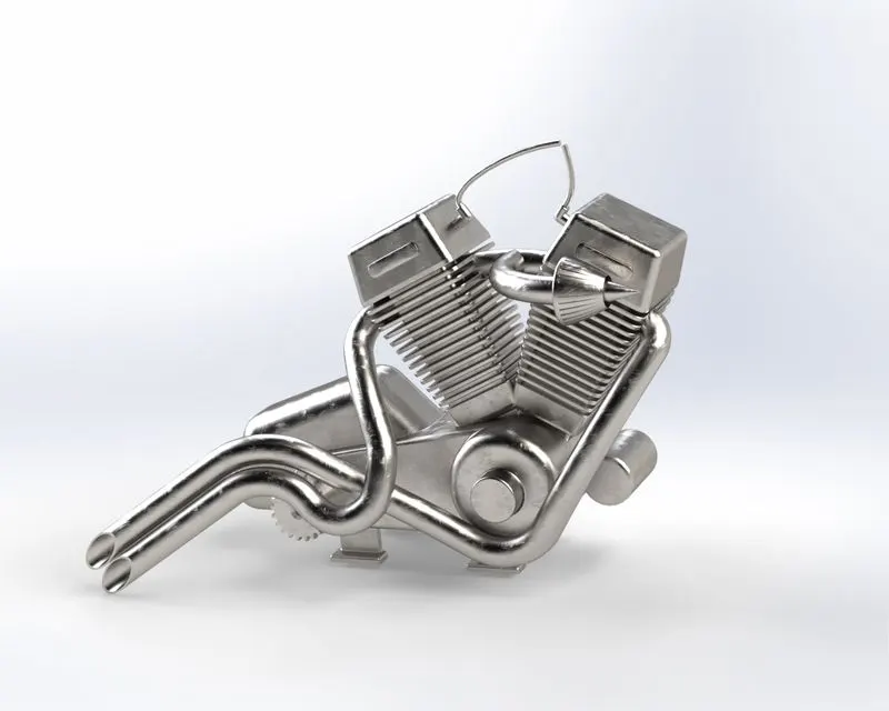
ENGINE
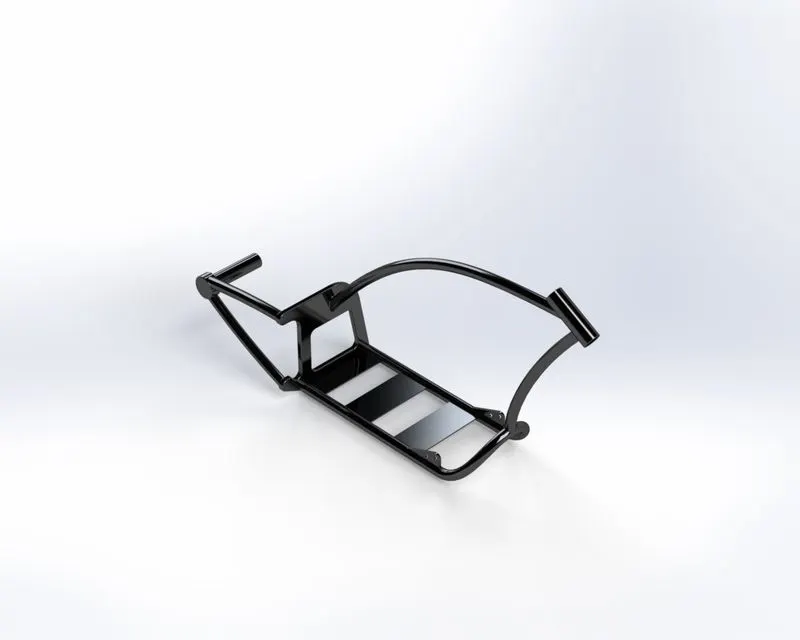
CHASSIS
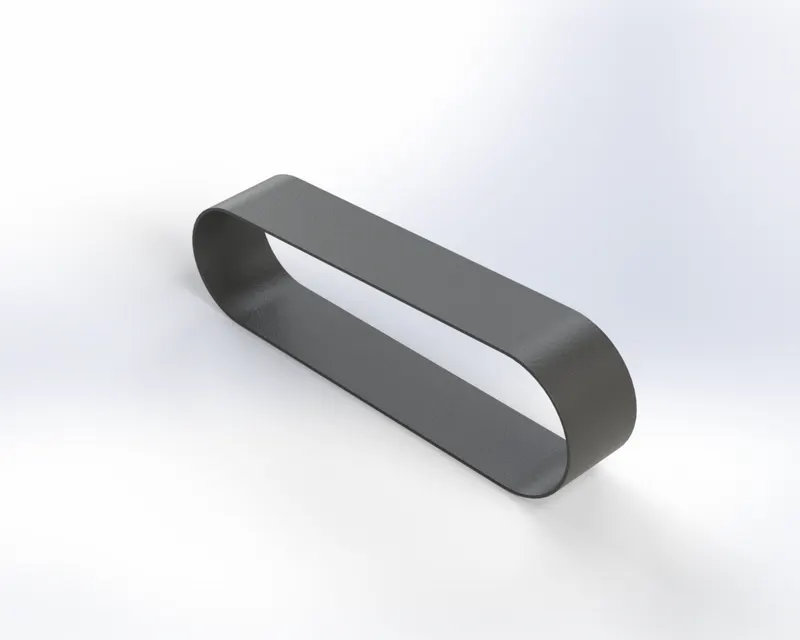
TRANSMISSION BELT
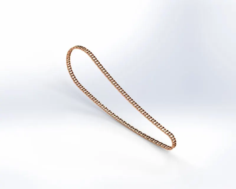
CHAIN
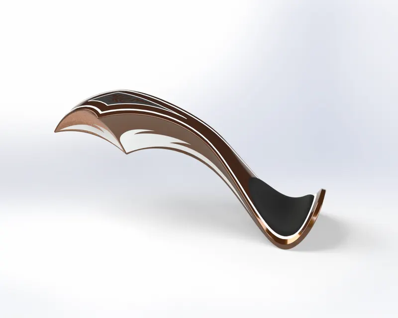
GASTANK
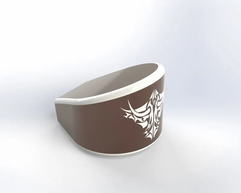
OIL TANK
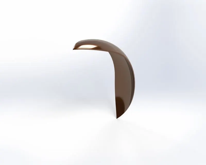
FRONT FENDER
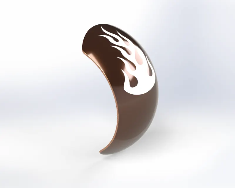
REAR FENDER
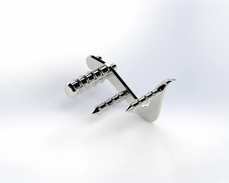
PEDAL
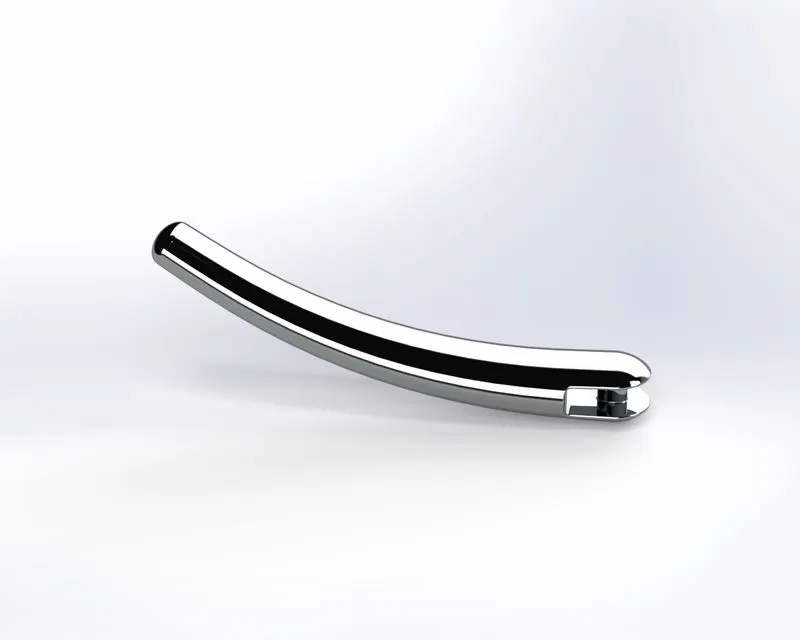
KICKSTAND
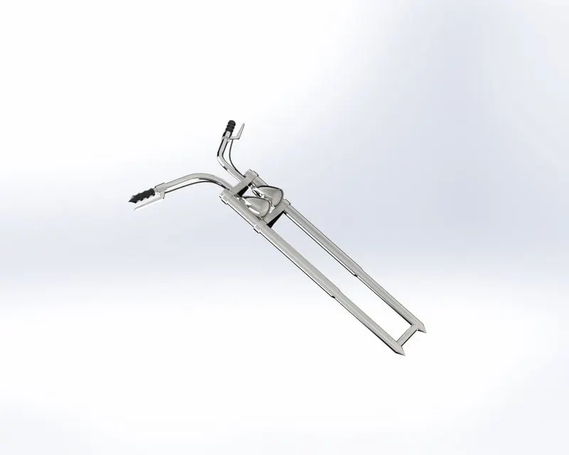
FRONT FORK
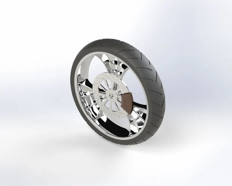
FRONT WHEEL
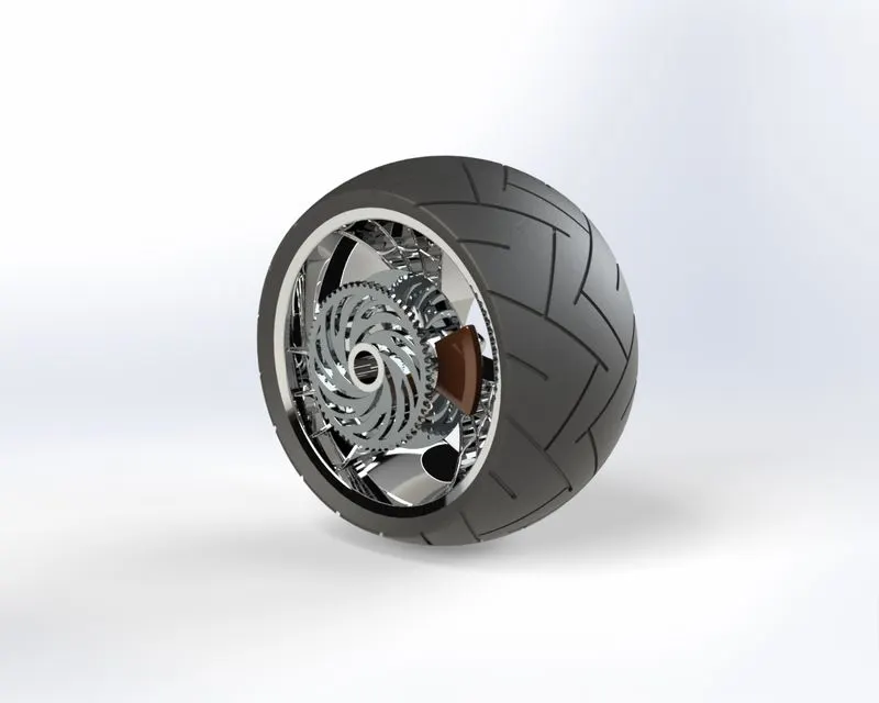
REAR WHEEL
ASSEMBLY RENDER IMAGES
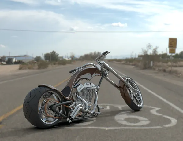
RENDER 1
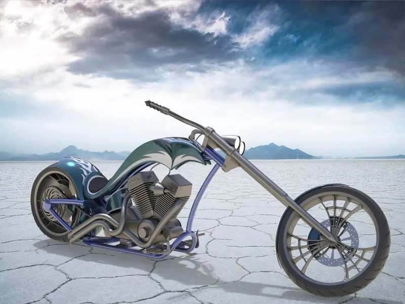
RENDER 2
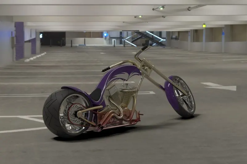
RENDER 3
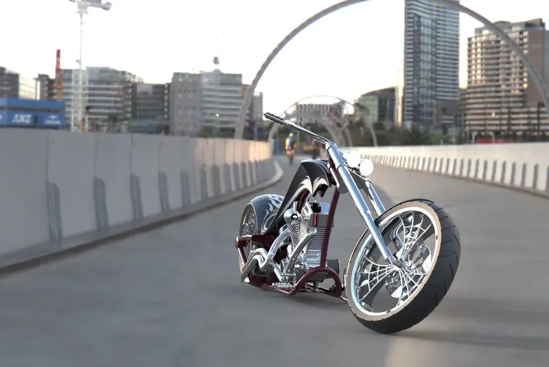
RENDER 4
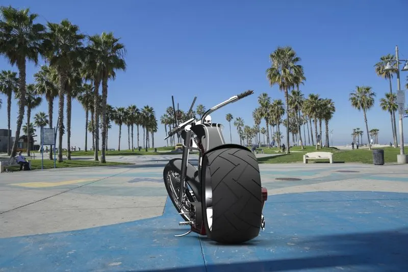
RENDER 5
CONCLUSION
- Parts of the chopper model are created with proper dimension, driving constraints, and fully defined sketches
- Assembly is done with proper mates and no intereference
- Appearance is given to each component along with decals for looks and branding
- camera and lights are added for proper realistic rendering
- Rendering is done using solidworks visualize with proper material appearance, environment, and backplates
- Conclusively Solidworks is a great tool for concept ideation, parts creation, end product visualization, drawing creation for fabrication