Week 6-Meshing of Hood Challenge
AIM: To mesh the components of an Automibile's Hood with proper mesh flow and mesh quality assuarance.
The detailed steps while performing the mesh are described below.
STEP 1: Mid-surfacing
Sub Steps include:
A. Checking and correcting geometrical errors in the parent body.
B. Checking the thickness and mid-surfacing using a suitable method.
C. Creating property and material cards for various components formed.
D. Correcting geometrical errors before proceeding for meshing.
STEP 2: Meshing and checking for quality criteria
A. Mesh the individual components with proper mesh size and quality criteria.
B. Normals are checked and comparison is done for feature capturing.
Step 1: Mid-surfacing
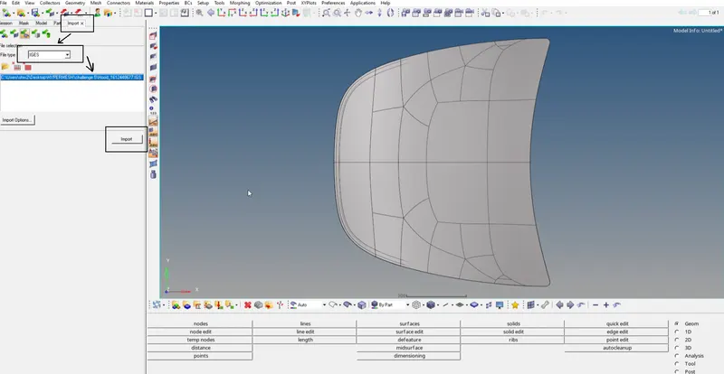
Fig: Imoprting the file and solid bodies are deleted.
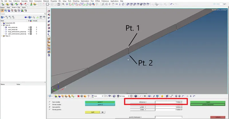
Fig: Finding thickness for different places in the parts and solid bodies are deleted.
GEOM >>>> MIDSURFACE >>>> CHOOSING SUITABLE METHOD
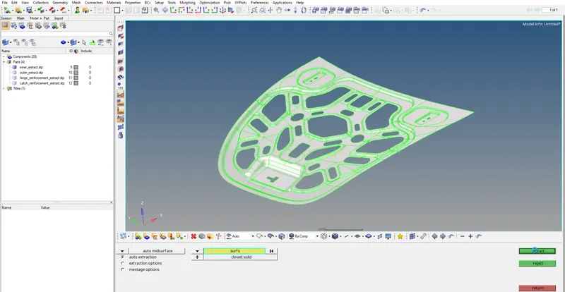
Fig: Mid surfacing using selective method and new component is created.
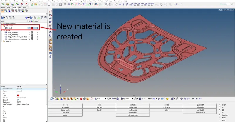
Fig: Material ID is created as Steel.
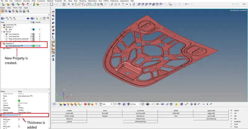
Fig: Property ID is created and thickness as well as material is added.
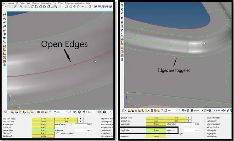
Fig: Open edges are toggeled.
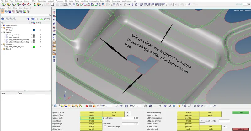
Fig: Various edges are toggeled.
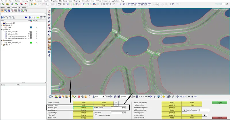
Fig: Washer split is formed for proper mesh flow at the boundaries.
Fig: New face is formed.
Similarly, all the steps are performed for other components before mesh creation.
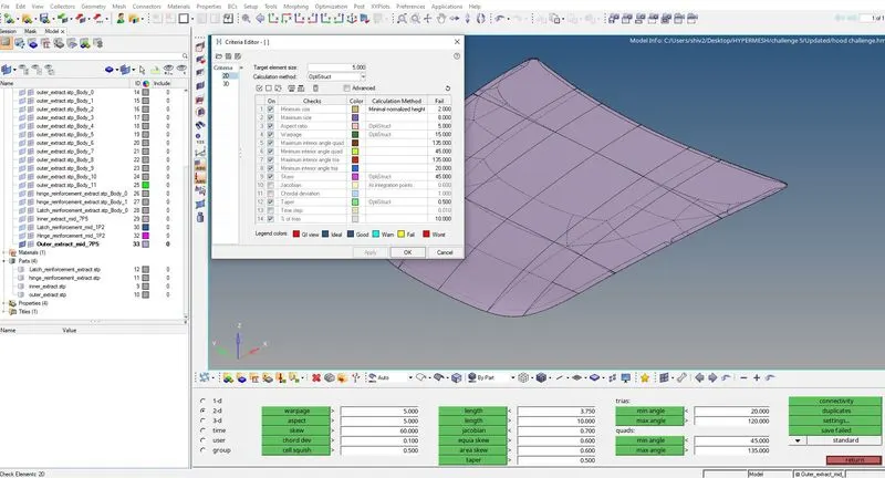
Fig: Setting quality settings under Tools >>> Check elements >>> Settings
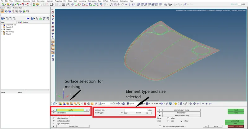
Fig: Selection of mesh size and element type as mixed.
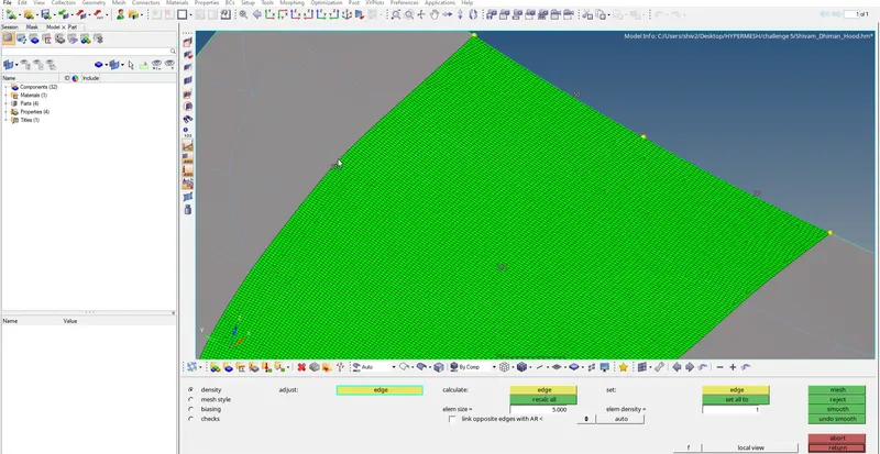
Fig: Numbers at the edges are managed to avoid lot number of opposite trias, rotating quads etc.
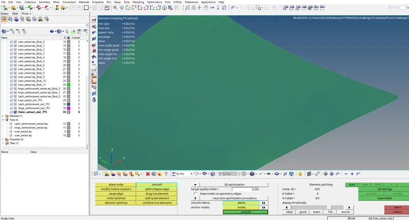
Fig: Zero quality errors
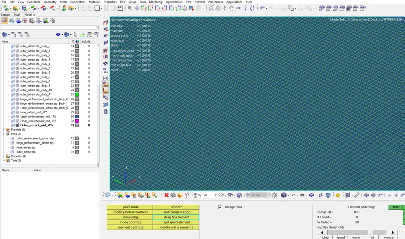
Fig: Proper Mesh flow is observed.
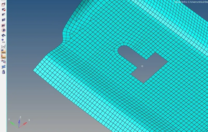
Fig: Good mesh flow.
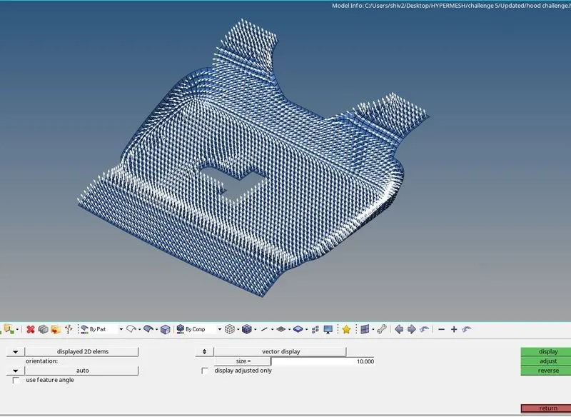
Fig: vector normals are checked for elements.
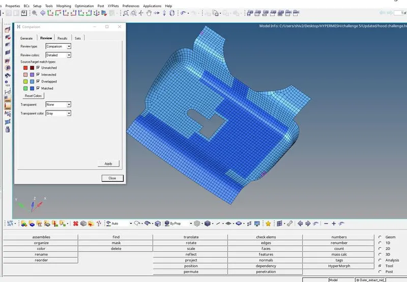
Fig: Components are compared between surface and elements to ensure feature capture and overlapping.
Similarly, all the steps are done for different components.
Conclusion:
Hypermesh is a tool with easy clean-up tools to ensure proper mesh flow.